8
11
WARNING: RISK OF PERSONAL INJURY.
Always disconnect tool from power source
before making any adjustments, installing
or changing accessories.
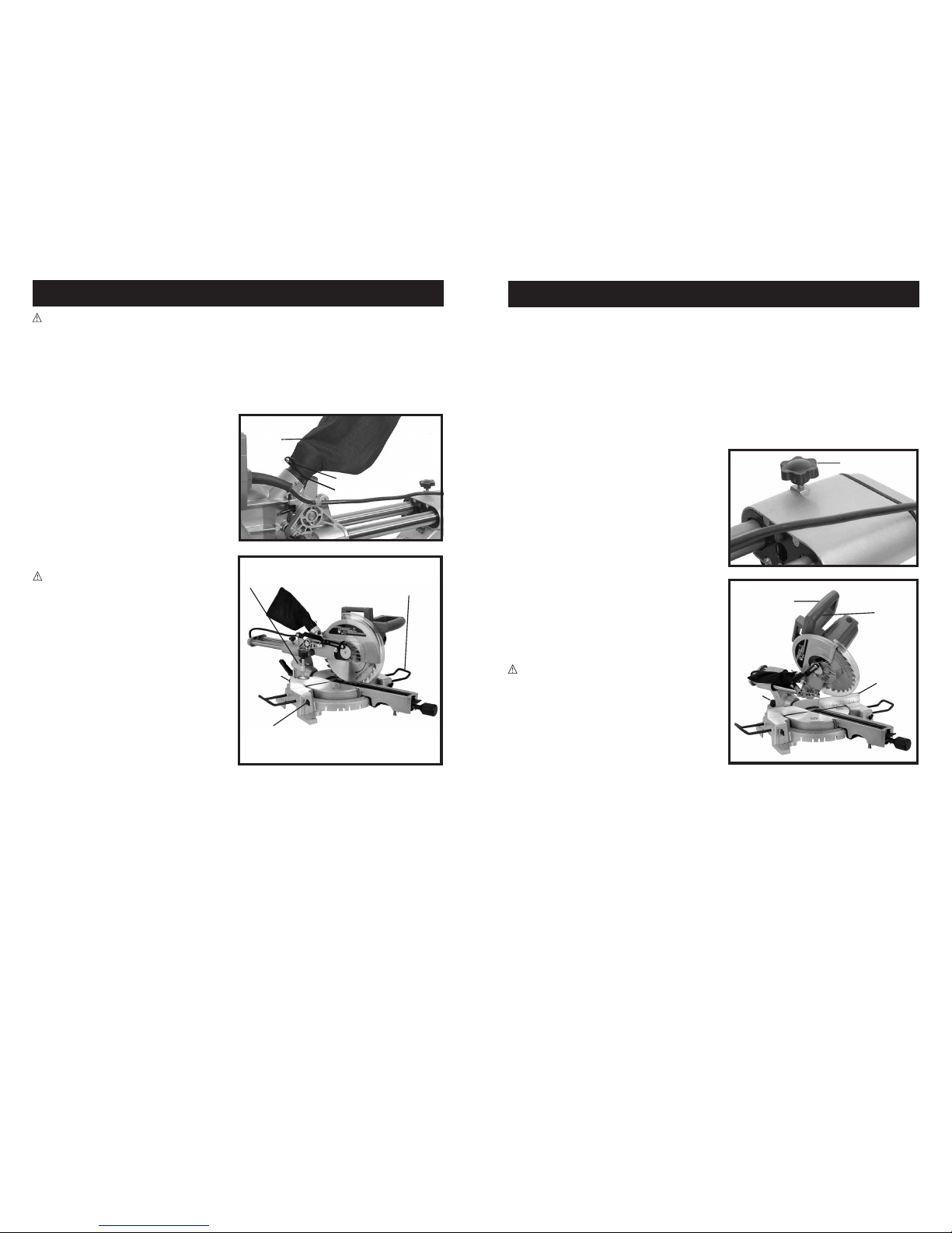
To Adjust the Miter Angle
1. (SEE FIGURE 7) The miter angle of a cut may
be adjusted 0 - 45° to the right or left. To do
so, loosen the miter lock knob (1) located at
the front of the table.
2. Move the handle to the right or left until the
desired miter angle of cut is indicated by the
miter scale (2) located on the base. Then, tighten
the handle to lock the miter Angle in place.
Unlocking Saw Cutting Arm
NOTE: The unit is packaged with the saw arm
in the lock down position.
1. Press down on the control handle enough to
take spring tension off of the lock down pin (1).
2. (See Figure 5) While holding down the control
handle, pull out on the lock down pin to
release the saw arm (2). Turn the pin
90 degrees to rest in the unlocked
(shallow slot) position.
3. Slowly let the saw arm rise to the
upright position.
Locking Cutting Arm in the Down Position
1. Press downward on control handle and lower the saw arm.
2. (See Figure 5) With arm down, pull out and turn the lock pin (1) 90 degrees to the locked
(deep slot) position.
3. Release the pin allowing it to engage the saw arm.
CAUTION: When carrying you miter saw or transporting it from one location to another, the saw
cutting arm should be locked in the down position and the saw should be carried by the handle.
Installing the Laser Batteries (Figure 6)
1. Turn the On/Off rocker switch (1) to the
off “O” position.
2. Remove the battery cover Phillips head
screw (2). Lift and remove the battery
cover (3), rear (screw end) first.
3. Insert new "AAA" size alkaline type
batteries (4), paying attention to proper
polarity (+ / -) installation direction.
4. Replace the battery cover and screw.
Figure 5
(1) Lock Down Pin
(2) Saw Arm
Figure 6
(1) Rocker Switch
(2) Phillip Head Screw
(3) Battery Cover
ADJUSTMENTS
(1) Miter Lock Knob
(2) Miter Scale
Figure 7
The On/Off Trigger Switch
CAUTION: Before plugging in the Miter Saw,
check the operation of the Trigger (1). Do not
operate the miter saw if the trigger is not
operating properly.
1. (SEE FIGURE 11) To start on the miter saw,
simply squeeze the On/Off trigger switch (1).
2. To stop the tool, release pressure on the
On/Off trigger switch.
Laser Aided Sighting (Figure12)
1. To activate the laser-sighting guide, move the
rocker switch (1) to the on “I” position. The
laser will project a narrow beam of red light
in line with the saw blade.
2. Align the light beam with the marked cut line
on the work piece.
3. To turn off the laser cutting guide, move the
rocker switch to the off “O” position.
CAUTION: LASER RADIATION - Do not stare
into the beam. Use of controls or adjustments
or performance of procedures other than
those specified in this instruction manual
may result in hazardous radiation exposure.
1. Laser radiations on work table - Do not stare
into reflected light from work surface.
2. Avoid exposure - Laser light is emitted from
the housing front aperture. Do not stare into
the aperture.
3. Do not disassemble laser.
4. Operate laser only when cutting. Turn laser
off after use.
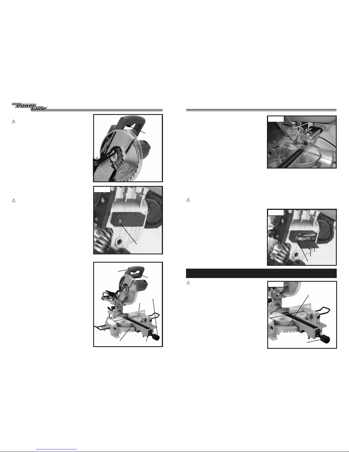
Making a Miter Cut
1. (See Figure 13) Raise the control handle (1)
up to allow positioning of the workpiece.
2. Loosen the miter locking knob (2), press down
on the miter thumb lever (3) and rotate the
cutting arm until the miter table pointer aligns
with the desired angle on the scale. Tighten the
miter locking knob.
3. Grasp the workpiece firmly with one hand and
secure it flat on the miter table with one edge
securely against the fence (5). Turn on the
laser-sighting guide. Adjust the workpiece to
align the cut-line with the Red laser beam
or saw blade. Use the material clamp
when possible.
CAUTION: When cutting a large workpiece,
make sure its entire length is properly
supported. If necessary, use a roller stand
(not included) with a larger workpiece.
Figure 11
Figure 13
Figure 12
(1) Trigger
(1) Rocker Switch
(2) Miter Lock Knob
(1) Control Handle
(5) Fence
(6) Trigger
Switch
(3) Miter Thumb Lever
(4) Miter Table Pointer