Power One ZM00056 User manual

REV. 1.2 JUN 11, 2007 www.power-one.com Page 1 of 8
USB-I
2
C Interface Adapter Kit
User Manua
l
USB to I2C Interface Adapter Kit
Model ZM00056-KIT
User Manual

REV. 1.2 JUN 11, 2007 www.power-one.com Page 2 of 8
USB-I
2
C Interface Adapter Kit
User Manua
l
TABLE OF CONTENTS
Section Topic Page
INTRODUCTION ........................................................................................................................................................ 3
1. REFERENCE DOCUMENTS....................................................................................................................... 3
2. DESCRIPTION............................................................................................................................................. 3
3. SETUP ......................................................................................................................................................... 4
3.1 GUI Installation ....................................................................................................................................... 4
3.2 Connecting the Adapter......................................................................................................................... 5
4. OPERATION ................................................................................................................................................ 6

REV. 1.2 JUN 11, 2007 www.power-one.com Page 3 of 8
USB-I
2
C Interface Adapter Kit
User Manua
l
Introduction
The USB to I2C interface adapter kit includes a USB to I2C interface adapter part number ZM00056 and a 4-foot
I2C cable. The adapter is intended for communication between a PC equipped with a USB port and the I2C
interface on a ZM7100 or ZM7300 series Digital Power Manager.
1. Reference Documents
The I2C-Bus Specification, Version 2.1, Philips Semiconductors
ZM7100 Digital Power Manager. Data Sheet
ZM7300 Digital Power Manager. Data Sheet
Z-Alliance Graphical User Interface Version 6.0.0 or later
2. Description
The adapter is shown in Figure 1. The dimensions of the adapter are approximately 3” by 1” by 0.75”.
LED Indicator USB Connector
I2C Connector
TOP VIEW
BOTTOM VIEW
Figure 1. USB to I2C Interface Adapter Model ZM00056
The I2C connector is a Tyco Electronics connector part number 4-943197-1. The pinout of the connector is shown
in Figure 2.
Figure 2. Pinout Of I2C Connector
SCL NC SDA GND

REV. 1.2 JUN 11, 2007 www.power-one.com Page 4 of 8
USB-I
2
C Interface Adapter Kit
User Manua
l
The 4-foot I2C cable shown in Figure 3 is used to connect the adapter to a board with ZM7100 or ZM7300 series
Digital Power Managers. For proper interface, the board needs to have the Tyco connector mentioned above or
equivalent.
Figure 3. I2C Cable
3. Setup
3.1 GUI Installation
1. Launch the GUI Installer
2. Follow directions on the screen. When the warning message shown in Figure 4 appears, click Continue
Anyway and complete the installation
Figure 4. Software Installation Warning Message
Note: Drivers for the USB to I2C interface adapter are downloaded during installation of the GUI.

REV. 1.2 JUN 11, 2007 www.power-one.com Page 5 of 8
USB-I
2
C Interface Adapter Kit
User Manua
l
3.2 Connecting the Adapter
1. Plug the adapter into a USB port on the host PC as shown in Figure 5.
Figure 5. Adapter Plugged Into USB Port
2. If the adapter is plugged in for the first time, the Windows will start the Found New Hardware Wizard. Allow
Windows searching for the software and click Next in the Welcome to the Found New Hardware Wizard
window shown in Figure 6
Figure 6. Welcome to the Found New Hardware Wizard Window

REV. 1.2 JUN 11, 2007 www.power-one.com Page 6 of 8
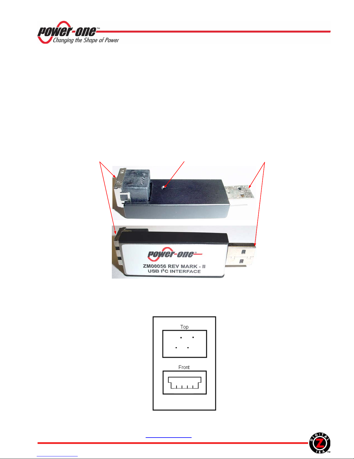
USB-I
2
C Interface Adapter Kit
User Manua
l
3. In the next window, select Install the software automatically and click Next
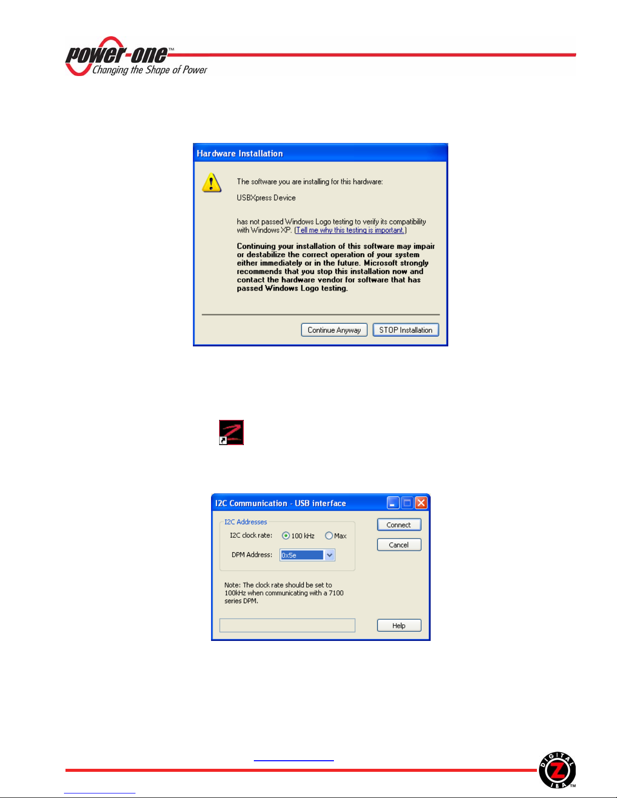
4. When the warning message shown in Figure 7 appears, click Continue Anyway and complete the installation
Figure 7. Hardware Installation Warning Message
4. Operation
1. When the adapter is plugged in the USB port, the red LED on the top of the adapter will start flashing every 3s,
indicating that the adapter is properly powered and in the idle mode.
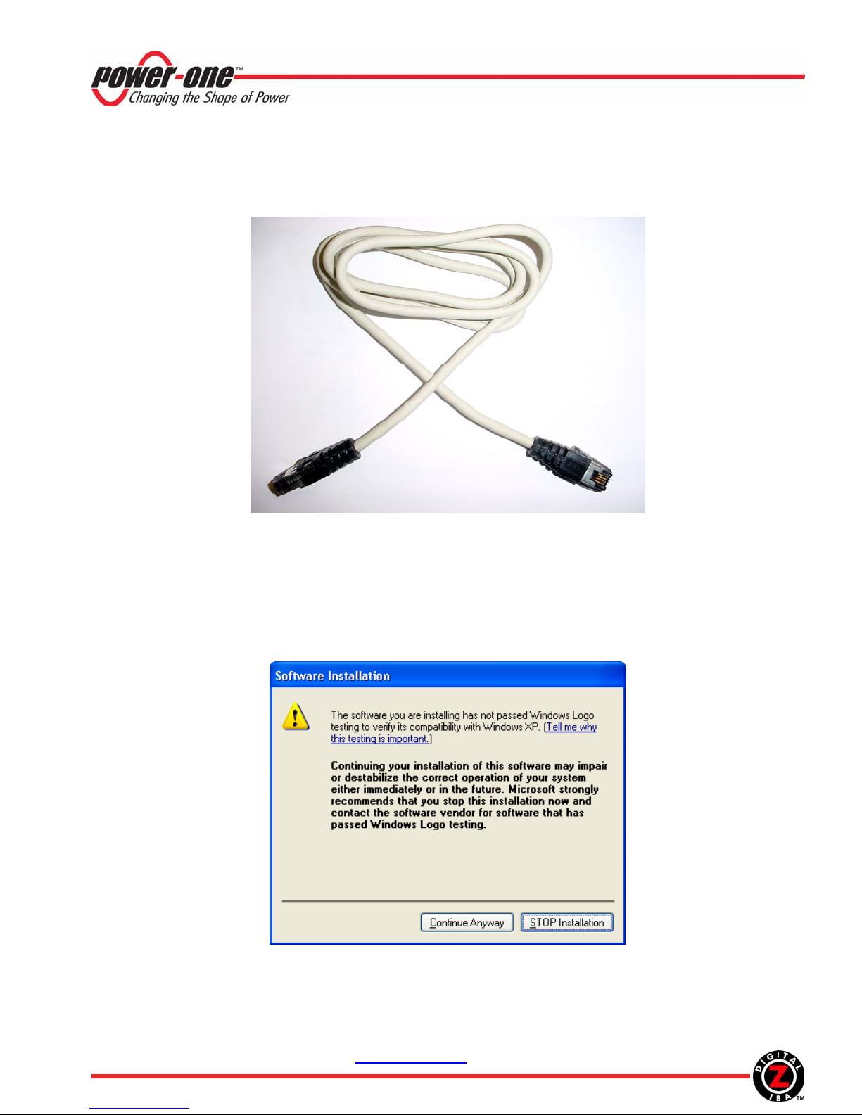
2. Connect the adapter to the target board using the enclosed I2C cable.
3. Double-Click the maXyz icon to launch the GUI
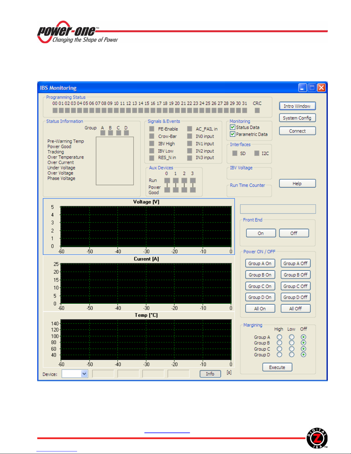
4. Click Operate System in the Introduction Window. The IBS Monitoring window shown in Figure 9 will
appear
5. Click Connect in the IBS Monitoring window. The USB interface window shown in Figure 8 will appear
Figure 8. USB Interface Window
6. Select the DPM address according to the settings on the target board and an appropriate I2C transmission
speed.
7. Click Connect. The IBS Monitoring window will start displaying status and parametric information as shown
in Figure 10. The LED will be ON during periods when data is transmitted over the I2C interface.

REV. 1.2 JUN 11, 2007 www.power-one.com Page 7 of 8
USB-I
2
C Interface Adapter Kit
User Manua
l
Troubleshooting Tip: If the USB connection is not established, the Serial Interface window will appear. Close
the window, unplug and plug back the USB cable, and repeat steps 5 to 7.
Figure 9. IBS Monitoring Window, Communication Is Not Established

REV. 1.2 JUN 11, 2007 www.power-one.com Page 8 of 8
USB-I
2
C Interface Adapter Kit
User Manua
l
Figure 10. IBS Monitoring Window, Communication Is Established
This manual suits for next models
1
Table of contents
Popular Adapter manuals by other brands

Enercell
Enercell Enercell 273-358 quick start guide

Kenwood
Kenwood KCA-SR50 - Complete Sirius Satellite Radio... instruction manual

D-Link
D-Link DUB-E100 Quick installation guide

Cisco
Cisco PA-4R-DTR Installation and configuration

Linksys
Linksys WUSB54G Product data

Edimax
Edimax EW-7822ULC / UT Quick installation guide