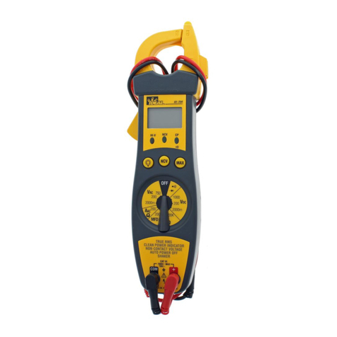
Power Probe PPDCM80 User manual

User’s
Manual
• Amp Clamp - Page 2
• Pinza amperimétrica digital - Página 21
• Pince ampèremétrique numérique - Page 41
• Digitale strommesszange - Seite 59
AMP CLAMP
PPDCM80

- 2 -
- 3 -
1. SAFETY INFORMATION .............................................................. 3
1.1 Preparation.......................................................................... 3
1.2 During use ........................................................................... 3
1.3 Safety Symbols.................................................................... 4
1.4 Maintenance........................................................................ 5
2. DESCRIPTION.............................................................................. 5
2.1 Front Panel.......................................................................... 5
2.2 LCD Display......................................................................... 7
3. SPECIFICATIONS......................................................................... 7
*HQHUDO6SHFL¿FDWLRQV......................................................... 7
7HFKQLFDO6SHFL¿FDWLRQV ...................................................... 8
4. Operating Instructions.............................................................. 12
4.1 Reading Hold..................................................................... 12
4.2 Relative Mode.................................................................... 12
4.3 Frequency/Duty Cycle Switch............................................ 12
4.4 Manual Range ................................................................... 13
4.5 Switching Functions........................................................... 13
4.6 Backlight/Clamp Light........................................................ 13
4.7 Auto Power Off ..................................................................13
4.8 Preparing for Measurement............................................... 14
4.9 AC/DC Current................................................................... 14
4.10 AC Voltage....................................................................... 15
4.11 DC Voltage....................................................................... 15
4.12 Frequency/Duty Cycle ..................................................... 16
4.13 Resistance....................................................................... 17
4.14 Diode ............................................................................... 17
4.15 Capacitance..................................................................... 18
4.16 Continuity......................................................................... 18
4.17 Temperature .................................................................... 19
4.18 Non-Contact Voltage (NCV) ............................................19
5. MAINTENANCE......................................................................... 19
5.1 Replacing the batteries...................................................... 19
5.2 Replacing test leads .......................................................... 20
6. ACCESORIES............................................................................ 20
EN
PPDCM80

- 3 -
1. Safety Information
Warning
Read and follow all safety guidelines outlined in this manual before
use to prevent personal injury or damage to the meter.
7KLV PHWHU PHHWV *%7 GLJLWDO PXOWLPHWHU JHQHUDO VSHFL¿FDWLRQV
in accordance with GB4793.1-1995 (EN61010-1,EN61010-2-032) safety
requirements for electronic measuring instruments with and over-voltage category
of CAT Ill 600V and pollution degree of 2.
Follow all safety instructions to ensure safe usage of the meter.
Proper usage and protection will ensure a long life of the meter.
1.1 Preparation
• When using the meter, users must follow standard safety rules:
ƕUse protection against electrical shock
ƕDo not misuse the instrument
• Check the meter for damage during transport
• Check the test leads for damage to the insulation or wires before use.
• Only use the test leads provided with the meter. Re- place only with similar leads
ZLWKPDWFKLQJVSHFL¿FDWLRQV
1.2 During Use
• Always select the proper function and range before measurement.
• 1HYHUH[FHHGWKHSURWHFWLRQOLPLWYDOXHVLQGLFDWHGLQWKHVSHFL¿FDWLRQVIRUHDFK
range of measurement.
• Do not measure voltages that exceed 600V between terminals and earth ground.
• Always be careful when working with voltages above 60V DC or 30V AC RMS.
.HHS¿QJHUVEHKLQGWKHSUREHEDUULHUVZKHQPDNLQJYROWDJHPHDVXUHPHQWV
• Choose the highest range when the value to be mea- sured is unknown
beforehand.
EN
PPDCM80

- 4 -
- 5 -
• Disconnect leads from circuit before switching func- tions/ranges.
• Turn off power and discharge capacitors before mea- suring resistance,
capacitance, diodes or continuity.
• Do not connect the meter to a voltage source while in current, resistance,
capacitance, diode or continuity modes.
• Do not place the meter in any environment with high pressure, high temperature,
dust, explosive gas or vapor.
• (QVXUHWKHPHWHUZRUNVSURSHUO\E\WHVWLQJDNQRZQYROWDJHVRXUFH¿UVW,IQRW
working properly, the protective equipment may be damaged; have the meter
serviced be- fore using.
• Do not use the meter with the battery cover not se- curely in place.
1.3 Safety Symbols
Note-Important safety information, refer to the instruction manual.
Application around and removal from UNINSULATED HAZARDOUS
LIVE conductors is permitted.
Caution, possibility of electric shock
Equipment protected throughout by double insula- tion or reinforced
insulation.
&RQIRUPVWR8/67'&HUWL¿HGWR
CSA STD C22.2 NO.
61010-1, 61010-2-032,61010-2-033
Complies with European (EU) safety standards
Earth (ground) TERMINAL
Direct current
Alternating current
CAT III: MEASUREMENT CATEGORY III is applicable to test and measuring
circuits connected to the distribution part of the building’s low-voltage MAINS
installation.
EN
PPDCM80
- 5 -
1.4 Maintenance
• Maintenance/calibration should only be performed by professionals.
• Before opening the case, always disconnect test leads from all energized circuits.
• When the “ “ symbol appears, replace the batter- ies to avoid incorrect
readings.
• Clean meter with a damp cloth and mild detergent; do not use chemical solvents
on the meter.
• Turn the rotary switch to the OFF position when the meter is not in use.
• If the meter is not going to be used for an extended period of time, remove the
batteries and avoid storing in a hot/humid environment.
2. Instrument Description
• This meter is a portable, professional instrument with a digital LCD display with
back-light for easy reading.
• Easy to use with one hand with overload protection and low battery indication.
Ideal for professionals, educational or home use.
• Functions include: AC/DC current, AC/DC voltage, resistance, capacitance,
continuity, diodes, frequency, duty cycle, and temperature.
• Auto-range function.
• Display hold.
• Avg. responding for AC current/voltage.
• Non-contact voltage measurement.
• Frequency measurement through clamp.
• Automatic power off feature.
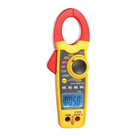
2.1 Front Panel (See Image on next page)
1.Current clamp head.
2.NCV Indicator.
3.Function buttons.
4.LCD screen.
5.Voltage, resistance, capacitance, frequency, diode, continuity, and temperature
input jack.
6.Common input.
7.Rotary Switch.
8.Clamp center indicator.
9.NCV sensor.
EN
PPDCM80

- 6 -
EN
PPDCM80
3080912
AMP CLAMP

- 7 -
- 7 -
2.2 LCD Display
6SHFL¿FDWLRQV
Meter should be calibrated annually at 18°C- 28°C with a relative humidity of <80%.
*HQHUDO6SHFL¿FDWLRQV
Auto-range Yes
Overload protection: CAT III 600V
Max. voltage between ter- minals and
earth ground: 600V DC or AC
Operating altitude: PIW
Display: 3 3/4 digit LCD display
Max. reading: 4000
Polarity Indication: display automatically shows “-”
Over-range Indication: display shows “OL” or “-OL”
Power: 3 x 1.5V AAA Batteries
Low Battery Indication: “” will appear on the display.
7HPSHUDWXUHFRHI¿FLHQW less than 0.1 x accuracy/°C
Operating temperature: 18°C~28°C (64°F~84°F)
Storage temperature: -10°C~50°C (14°F~122°F)
Operating Humidity: <80%
Operating Environment: Indoor Use
Pollution degree: 2
Dimensions: 195x80x45mm
Weight: approx. 195g (including batteries)
EN
PPDCM80
- 8 -
- 9 -
7HFKQLFDO6SHFL¿FDWLRQV
AC Current
Range Resolution Accuracy
4 A 1 mA
±(2.5% of reading +5 digits)40 A 10 mA
80 A 100 mA
• Max. input current: 80A AC
• Frequency range: 40Hz~400Hz
DC Current
Range Resolution Accuracy
4 A 1 mA
± (2,5 % of reading + 5 digits)40 A 10 mA
80 A 100 mA
• Max. input current: 80A DC
DC Voltage
Range Resolution Accuracy
4 V 0,001 V
± (0,8 % of reading + 3 digits)
40 V 0,01 V
400 V 0,1 V
600 V 1 V
• ,QSXWLPSHGDQFH0ȍ
• Max. input voltage: 600V DC
Note:
At small voltage ranges, unsteady readings will appear before the test leads make
contact with the circuit. This is normal since the meter is highly sensitive. When the
test leads are connected to the circuit, the true reading will be shown.
EN
PPDCM80

- 9 -
AC Voltage
Range Resolution Accuracy
4 V 0,001 V
± (1,0 % of reading + 3 digits)
40 V 0,01 V
400 V 0,1 V
600 V 1 V
• ,QSXWLPSHGDQFH0ȍ
• Max. input voltage: 600V AC RMS
• Frequency range: 40Hz~400Hz
Note:
At small voltage ranges, unsteady readings will appear be- fore the test leads
make contact with the circuit. This is nor- mal since the meter is highly sensitive.
When the test leads are connected to the circuit, the true reading will be shown.
Frequency
Hz Position
Range Resolution Accuracy
9,999 Hz 0,001 Hz
± (0,5 % of reading + 3 digits)
99,99 Hz 0,01 Hz
999,9 Hz 0,1 Hz
9,999 kHz 0,001 kHz
99,99 kHz 0,01 kHz
999,9 kHz 0,1 kHz
9,999 MHz 0,001 MHz
A Position (Clamp)
Range Resolution Accuracy
99,99 Hz 0,01 Hz
± (0,5 % of reading + 3 digits)999,9 Hz 0,1 Hz
9,999 kHz 1 Hz
• Frequency range: 40Hz~10kHz
• Input signal range: >1A AC RMS. As current increases, Frequency increases as
well.
• Max. input current: 80A AC
EN
PPDCM80
- 10 -
- 11 -
V Position
Range Resolution Accuracy
99,99 Hz 0,001 Hz
± (1,5 % of reading + 5 digits)999,9 Hz 0,01 Hz
9,999 kHz 0,1 Hz
• Frequency range: 40Hz~10kHz
• Input signal range:>0.2V AC RMS. As current increases, frequency increases
as well.
• ,QSXWLPSHGDQFH0ȍ
• Max. input voltage: 600V DC/AC RMS
Duty Cycle
Range Resolution Accuracy
0,5 - 99,5 % 0,1 % ± 3,0 %
Hz Position
• Frequency range: 40Hz~10MHz
• Input signal range: >2V AC RMS. As voltage increases, frequency increases as
well.
• Max. input voltage: 250V AC RMS
A Position (Clamp)
• Frequency range: 40Hz~1kHz
• Input signal range: >4A AC RMS. As current increases, fre- quency increases
as well.
• Max. input current: 80A AC
V Position
• Frequency range: 40Hz~10kHz
• Input signal range: >0.6V AC RMS. As voltage increases, frequency increases
as well.
• Max. input voltage: 600V AC RMS
EN
PPDCM80
- 11 -
Resistance
Range Resolution Accuracy
ȍ ȍ
± (0.8 % of reading + 3 digits)
Nȍ Nȍ
Nȍ Nȍ
Nȍ Nȍ
0ȍ 0ȍ
0ȍ 0ȍ ±(1.2% of reading +3 digits)
• Open circuit voltage: 1V
• Overload protection : 250V DC/AC RMS
Continuity
Range Resolution Accuracy
9,999 Hz ȍ If the measured resistance is less
WKDQȍWKHEX]]HUZLOOVRXQG
• Overload protection: 250V DC/AC RMS
Capacitance
Range Resolution Accuracy
4 nF 0,001 nF
± (4.0 % of reading + 3 digits)
40 nF 0,01 nF
400 nF 0,1 nF
ȝ) ȝ)
ȝ) ȝ)
ȝ) ȝ)
4 mF 0,001 mF
40 mF 0,01 mF
• Overload protection: 250V DC/AC RMS
EN
PPDCM80
- 12 -
- 13 -
Diode
Range Resolution Accuracy
0.001V Shows approx. forward voltage drop
of a diode.
Temperature
Range Resolution Accuracy
-20°C~1000°C 1°C ± (0,8 % de lecture + 3 digits)
-4°F~1832°F 1°F
• Overload protection: 250V DC/AC RMS
4. Operating Instructions
4.1 Reading Hold
• To hold a reading on the display,press and the current reading will be held
on the display.
• Press to release the hold and return to normal display.
4.2 Relative Mode
• Relative Mode is only available for DC voltage, DC current, and capacitance
measurements.
• Press to enter relative mode; auto-range is disabled. The display will show
the value measured compared to the value when the button was pressed. Press
again to return to normal display.
Note:
When using relative mode, selct the appropriate range by pressing before
activating relative mode.
4.3 Frequency/Duty Cycle Switch
• In AC current or AC voltage modes, press to enter frequency mode. Press
in frequency mode to enter duty cycle mode. Press in duty cycle mode
to return to normal display. Pressing while the rotary switch is in the “Hz”
position will switch between frequency and duty cycle.
EN
PPDCM80
- 13 -
4.4 Manual range
The meter’s default range is “AUTO.” To select manual range, press to enter
manual range.
Each press of the button increases the range and returns to the lowest range when
pressed at the highest range. Hold the button to return to autorange.Manual range
cannot be used in current, frequency, duty cycle, diode, continuity, or temperature
modes.
4.5 Switching Functions
• In current and voltage positions, press to switch between AC and DC
modes.
• In the multifunction position, press to switch between resistance,
capacitance, continuity, and diode modes.
• In the temperature position, press to switch between Celsius and Fahrenheit
modes.
4.6 Back light/Clamp light
• For making measurements in dark areas, hold and the back light and clamp
light will turn on for 15 sec- onds before turning off.
• Hold while the back light/clamp light is on to turn it off manually.
• The back light and clamp light requires a large operating current, so use sparingly.
Note:
When the battery voltage drops below 3.6V the display shows symbol.
Sometimes when the back light is turned on, the symbol will appear because
of the large work- ing current needed.The batteries do not need to be replaced until
the symbol appears without the backlight on.
4.7 Auto Power Off
• After 15 minutes of non-use the meter will turn itself off. 1 min. before auto off the
meter will beep 5 times, then sound a long beep as the meter turns off.
• To turn the meter back on after auto off, press any button.
• Hold when turning on the meter to turn off the auto power off feature.
EN
PPDCM80
- 14 -
- 15 -
4.8 Preparing for Measurement
• Turn the rotary switch to turn on the meter. If the battery voltage is less than 3.6V,
the symbol will appear. Replace the batteries before use.
• symbol means the input signal should not exceed the limit indicated to protect
the meter from damage.
• Move the rotary switch to the correct measurement position and range.
• When connecting test leads to a circuit, connect the common lead before the hot
lead. When disconnecting, remove the hot lead before the common lead.
4.9 AC/DC Current
Warning
Electric shock hazard.
Remove test leads before measuring current.
• Move the rotary switch to the proper current position; DC current is the default
measurement. Press to return the display to zero if necessary.
• Hold the trigger and clamp one conductor to be measured.
• Measurement will be shown on the display.
• Press to switch to AC current.
• Clamp one conductor and the measurement will be displayed.
• In DC current, observe the”+” and”-” symbols on
• WKHFODPSLQGLFDWLQJWKHGLUHFWLRQRISRODULW\IRU'&FXUUHQWÀRZ
Note:
1. Clamping more than one conductor will not produce correct readings.
2. Place the conductor in the center of the clamp for the most precise readings.
3. Press in DC current before measurement to get the most accurate
measurement.
4. indicates maximum input current is 80A DC/AC (non- RMS)
EN
PPDCM80

- 15 -
4.10 AC Voltage
Warning
Electric shock hazard.
Use caution to avoid damage or personal injury. Maximum input voltage: 600V
AC RMS.
• Turn the rotary switch to the voltage position. Press to switch to AC voltage.
• Connect the red test lead to the INPUT jack and the black test lead to the COM
jack.
• Connect the test leads in parallel to the circuit under test.
• Read the measured voltage on the display.
Note:
1. In small voltage ranges, the display may show a reading before leads are
connected.This is normal because of the high sensitivity of the meter. Once the
leads are connected to a circuit, the true voltage will be displayed.
2. indicates maximum input voltage is 600V AC (non-RMS)
3. If measured voltage is greater than 750V AC RMS, the meter will sound an
alarm.
4.11 DC Voltage
Warning
Electric shock hazard.
Use caution to avoid damage or personal injury. Maximum input voltage: 600V
DC.
• Turn the rotary switch to the voltage position. The default setting is DC voltage.
• Connect the red test lead to the INPUT jack and the black test lead to the COM
jack.
• Connect the test leads in parallel to the circuit under test.
• Read the measured voltage on the display.
Note:
1. In small voltage ranges, the display may show a reading before leads are
connected.This is normal because of the high sensitivity of the meter. Once the
leads are connected to a circuit, the true voltage will be displayed.
2. indicates maximum input voltage is 600V DC.
3. If measured voltage is greater than 1000V DC, the meter will sound an alarm.
EN
PPDCM80

- 16 -
- 17 -
4.12 Frequency/Duty Cycle
Hz Position
• Turn the rotary switch to the Hz position to measure frequency.
• Press to switch to duty cycle. Press again to switch back to frequency.
A Position (Clamp)
Warning
Electric shock hazard.
Remove test leads before measuring current.
• Turn the rotary switch to one of the current positions.
• Hold the trigger and clamp one conductor to be measured.
• Press to switch to frequency measurement. Press again to switch to
duty cycle.
Note:
1. Clamping more than one conductor will not produce correct readings.
2. Frequency range is 10Hz-10kHz. Frequencies outside this range are possible to
be measured, but the meter cannot guarantee the accuracy of these measurements.
3. indicates maximum input current is 80A DC/AC (non-RMS).
V Position
Warning
Electric shock hazard.
Use caution to avoid damage or personal injury. Maximum input voltage: 600V
AC RMS.
• Turn the rotary switch to the voltage position. Press to switch to AC voltage.
• Connect the red test lead to the INPUT jack and the black test lead to the COM
jack.
• Press to switch to frequency measurement. Press again to switch to
duty cycle.
• Connect the test leads in parallel to the circuit under test.
• Read the measured voltage on the display.
Note:
1. Frequency range is 10Hz~10kHz. Frequencies outside this range are possible
to be measured, but the meter can- not guarantee the accuracy of these
measurements.
2. indicates maximum input voltage is 600V AC (non- RMS).
EN
PPDCM80

- 17 -
4.13 Resistance
Warning
Electric shock hazard.
Turn off all power and discharge all capacitors before making resistance
measurements.
• Turn the rotary switch to the position. The default setting is resistance.
• Connect the red test lead to the INPUT jack and the black test lead to the COM
jack.
• Connect the test leads in parallel to the circuit under test.
• Read the measured resistance on the display.
Note:
1. When the leads are not connected, the display will show ”OL”
:KHQWKHPHDVXUHGUHVLVWDQFH LVJUHDWHUWKDQ0ȍZDLWD IHZ VHFRQGV IRU
readings to stabilize.This is normal for high resistance measurements.
4.14 Diode
• Turn the rotary switch to the position. Press 3 times to switch to diode
mode.
• Connect the red test lead to the INPUT jack and the black test lead to the COM
jack.
• Connect the red lead to the anode(+) and the black lead to the cathode(-) of the
diode.
• Read the measured voltage on the display.
Note:
1. The meter shows the approximate forward-biased volt- age drop.
2. If the leads are not connected or reversed, the display will show ”OL”.
EN
PPDCM80

- 18 -
- 19 -
4.15 Capacitance
Warning
Electric shock hazard.
Turn off all power and discharge all capacitors before making resistance
measurements.
• Turn the rotary switch to the position.Press once to switch to capacitance
mode.
• Connect the red test lead to the INPUT jack and the black test lead to the COM
jack.
• Connect the test leads to the capacitor to be measured.
• Read the measured capacitance on the display.
Note:
1. When measuring large capacitances, wait a few seconds for readings to stabilize.
This is normal for high capacitance measurements (>4mF).
2. To improve the accuracy below 10nF measuring value, subtract the distributed
capacitance of meter and cable.
4.16 Continuity
Warning
Electric shock hazard.
Turn off all power and discharge all capacitors before making resistance
measurements.
• Turn the rotary switch to the position. Press 2 times to switch to diode
mode.
• Connect the red test lead to the INPUT jack and the black test lead to the COM
jack.
• Connect the test leads to the circuit under test.
• Read the measured resistance on the display.
• ,IWKHPHDVXUHGUHVLVWDQFHLVOHVVWKDQȍWKHEX]]HUZLOOVRXQG
Note:
:KHQWKHOHDGVDUHQRWFRQQHFWHGRULIWKHPHDVXUHGUHVLVWDQFHLV!ȍWKH
display will show “OL.”
EN
PPDCM80

- 19 -
4.17 Temperature
• Turn the rotary switch to the °C/°F position. The default setting is °C. Press
to switch to °F if necessary.
• Connect the red(+) end of the K-Type thermocouple to the INPUT jack and the
black(-) end to the COM jack.
• Place the tip of the thermocouple on the surface of the object to be measured.
• Read the measured temperature on the display.
4.18 Non-Contact Voltage (NCV)
Hold down the NCV button and move the tip of the clamp toward the conductor
XQGHUWHVW,IWKHGHWHFWHGYROWDJHLV!9$&506WKH1&9LQGLFDWRUZLOOÀDVK
and the buzzer will beep.
Note:
1. Do not rely solely on NCV detection to determine the presence of voltage.
Detection can be affected by socket design, insulation thickness, or other factors.
2. Interference from outside sources could accidentally trig- ger the NCV detector.
5. Maintenance
5.1 Replacing the batteries
Warning
To avoid electric shock, make sure that the test leads have been clearly moved
away from the circuit under measurement before opening the battery cover of
the meter.
Warning
Do not mix old and new batteries. Do not mix alkaline, standard (carbon-zinc), or
rechargeable (ni-cad, ni-mh, etc) batteries.
• If the sign appears, it means that the batteries should be replaced.
• /RRVHQWKH¿[LQJVFUHZRIWKHEDWWHU\FRYHUDQGUHPRYHLW
• Replace the exhausted batteries with new ones.
• 3XWWKHEDWWHU\FRYHUEDFNDQG¿[LWDJDLQWRLWVRULJLQDOIRUP
Note:
Do not reverse the polarity of the batteries.
EN
PPDCM80

- 20 -
- 21 -
5.2 Replacing Test Leads
Replace test leads if leads become damaged or worn.
Warning
Use meet EN 61010-031 standard, rated CAT III 600V, or better test leads.
6. Accessories
• Test Leads - Spec : 1000 V, 10 A 1 pair
• User’s manual 1 unit
• p3400 K-Type Thermocouple 1 unit
• AAA Batteries 3 units
EN
PPDCM80
Table of contents
Languages:
Other Power Probe Measuring Instrument manuals