Power Probe 3EZ User manual

Power Probe 3EZ
INTRODUCTION
Thank you for purchasing the Power Probe 3EZ (PP3EZ). The
PP3EZ includes all the powerful testing modes and features
of the Power Probe 3S plus now includes 2 new modes - EZ
Learning Mode and EZ Diagnostics Mode. The PP3EZ speeds
you through the diagnosing of 12 to 24 volt automotive elec-
trical systems. After connecting the PP3EZ’s clips to the ve-
hicle’s battery, the automotive technician can determine at a
glance, the voltage level and the polarity of a circuit without
running for a voltmeter or reconnecting hook-up clips from
one battery pole to the other. The power switch allows the
automotive technician to conduct a positive or negative bat-
tery current to the tip for activating and testing the function of
electrical components without wasting time with jumper leads.
WWW.POWERPROBETEK.COM
5000815

It allows you to follow and locate short circuits without wasting
precious fuses. The Power Probe can also test for continuity
with the assistance of its auxiliary without running to the bat-
tery as you would otherwise have to do with simple test lights.
The PP3EZ’s 20ft (extendable) cable allows you to test along
the entire length of the vehicle without constantly searching
for ground hook-ups.
Do not use the equipment for measurements on CAT II, CAT
III & CAT IV. An absolute must for every automotive technician
looking for a fast and accurate solution to electrical systems
diagnostics.
Before using the Power Probe 3EZ please read the instruction
booklet carefully.
If the equipment is used in a manner not specified by the
manufacturer, the protection provided by the equipment may
be impaired.
Warning! When the PP3EZ rocker switch is depressed bat-
tery current/voltage is conducted directly to the tip which
may cause sparks when contacting ground or certain circuits.
Therefore the power energized Power Probe could ignite
these vapors. Use the same caution as you would when using
an arc welder.
WWW.POWERPROBETEK.COM
2
INTRODUCTION CONTINUED

Product is not water resistant, please avoid water contact
during operation.
If the test leads need to be replaced, you must use a new one
which should meet EN 61010-031 standard.
The Power Probe 3EZ is NOT to be used with 110/220V
HOME electrical, it is only for use with 12-24V systems.
The Power Probe 3EZ Conforms to UL STD. 61010-1, 61010-2-
030 and 61010-031; Certified to CSA STD. C22.2 NO. 61010-1,
61010-2-030 and 61010-031.
To switch languages on the PP3EZ, with the hook up clips re-
moved from the battery, press and hold the right button. While
holding the right button, attach the hook up clips to the bat-
tery power. The language options will appear on the screen.
Choose the desired language by pressing the left button.
Press the right button to set the language.
WWW.POWERPROBETEK.COM
3
INTRODUCTION CONTINUED

WWW.POWERPROBETEK.COM
4
TABLE OF CONTENTS
Hook-up and quick self-test 5
Turning the Audio Tone On & O 5
Circuit Breaker 5
Voltage & Polarity testing 5
Continuity testing 6
Introduction to “EZ” 7
Guided Diagnostics 8
Testing Section 9
Continuity Testing 10
Activating components in hand 11
Testing trailer lights and connections. 13
Activating electrical components in the Vehicle 14
Activating electrical components with Ground 16
Checking for bad ground contacts 18
Following & Locating Short Circuits 19
Red/Green Indicator & Audio Tone 19
Flip Screen Function 19
Modes 20
Specifications 27
Replacement Parts 29
Power Probe warranty 29
Power Probe TeK Contact Details Back Cover
IMPORTANT TIP: When powering-up components, you can in-
crease the life of your Power Probe switch if you first press the
switch, then contact the tip to the component. The arcing will
take place at the tip instead of the contacts of the switch.

Unroll the Power Probe cable. Connect the RED battery hook-
up clip to the POSITIVE terminal of the vehicle’s battery. Con-
nect the BLACK battery hook-up clip to the NEGATIVE termi-
nal of the vehicle’s battery. When the PP3EZ is first connected
to a battery (power source), it will sound a quick start up tone
and then go into Voltmeter Mode (See Mode #1) and the 2
bright white LEDs (dual headlights) will be on to illuminate the
test area of the probe tip.
WWW.POWERPROBETEK.COM
5
HOOK UP AND QUICK SELF-TEST
TURNING AUDIO TONE ON & OFF
While the PP3EZ is in Voltmeter Mode, press the left button to
toggle the tone on or o. When the left button is pressed, if a
short high beep is heard, this means the audio tone is turned
on. If a short low beep is heard, the audio tone has turned o.

WWW.POWERPROBETEK.COM
6
TURNING AUDIO TONE ON & OFF
In Voltmeter Mode (Mode #1) with the circuit breaker tripped,
the display will show “Circuit Breaker Tripped”(see page 11-12
for detail) All other functions of the PP3EZ are still active. This
means that you can still probe a circuit and observe the volt-
age reading. When the circuit breaker is tripped, the PP3EZ
will NOT be able to conduct battery current to the tip even
when the power switch is pressed. Intentionally tripping the
breaker and using the PP3EZ to probe can be considered an
added precaution against accidental pressing of the power
switch.
CIRCUIT BREAKER

WWW.POWERPROBETEK.COM
7
INTRODUCTION TO “EZ”
The Power Probe 3EZ is the latest addition to the Power
Probe line of circuit testers. It includes all the powerful testing
modes and features of the Power Probe 3S and now includes
2 new modes- EZ Learning Mode and EZ Diagnostics Mode.
EZ Learning Mode will guide you through a step by step
familiarization of the PP3EZ, showing you how to operate the
PP3EZ and how the probe responds in certain testing condi-
tions.
EZ Diagnostics Mode will help guide you through specific
vehicle or component tests and let you know if readings ob-
tained are acceptable or outside of the desired specification.
EZ Learning Mode – Scroll the Menu down using the Left
Button until EZ LEARNING is highlighted on the menu. Select
EZ LEARNING by pressing the Right Button. EZ Learning will
now take you through a step by step process illustrating how
the probe responds and the dierent types of readings that
can be obtained. This mode is to be used for familiarization
and guidance only and is not a mode used for actual circuit
testing.
Once EZ LEARNING mode is selected, it must be scrolled
through from start to finish before it will exit EZ LEARNING
mode. You can also exit EZ Learning by disconnecting pow-
er from the probe and the probe will enter normal test mode
when re-connected. NOTE: If you see a flashing screen in the
menu it means go to that selection and press enter.

EZ Diagnostic Mode – Scroll the Menu down using the Left
Button until EZ DIAGNOSTICS is highlighted on the menu. Se-
lect EZ DIAGNOSTICS by pressing the Right Button. EZ DIAG-
NOSTICS are preset test modes for dierent vehicle system
tests.
The available tests listed are: Battery Check, Charge Test,
Fuse Test, Voltage Test, Component Test, 5V Ref.
Each test section includes a readable QR code that will ac-
cess online video content explaining the test procedure.
5V REF mode is used together with the Power Probe Tek 5V
Adapter Tip (# PPT5VA). With the Adapter Tip installed on the
probe and applying power, the probe will no longer output full
battery voltage. The 5 Volt Adapter will only output a current
limited 5V that can be used as a reference voltage to safely
power and test sensor and computer circuits.
FOR FULL EXPLANATIONS OF EACH TESTING MODE AND
SCREEN PLEASE GO TO:
www.powerprobetek.com/ezdiagnostics/ or scan the below
QR code:
WWW.POWERPROBETEK.COM
8
EZ DIAGNOSTICS

Continuity testing 10
Activating components out of vehicle’s electrical system 11
Testing trailer lights and connections. 13
Activating electrical components in the Vehicle 14
Activating electrical components with Ground 16
Checking for bad ground contacts 18
Following & Locating Short Circuits 18
WWW.POWERPROBETEK.COM
9
TESTING SECTION
WWW.POWERPROBETEK.COM
10
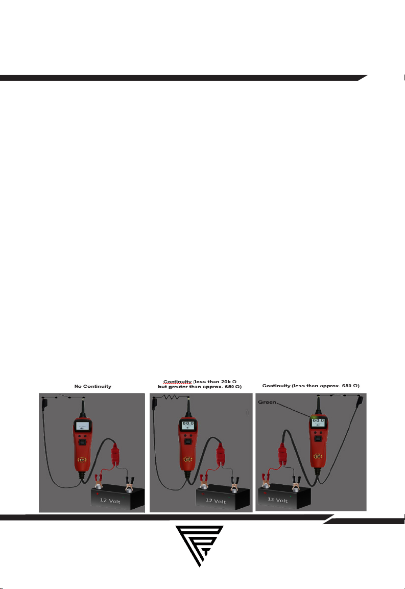
CONTINUITY TESTING
While the PP3EZ is in Voltmeter Mode, and by using the Pow-
er Probe tip in connection with chassis ground or the auxiliary
ground lead, continuity can be tested on wires and compo-
nents attached or disconnected from the vehicle’s electrical
system.
The PP3EZ indicates continuity using 2 resistance levels.
When the Power Probe tip has a resistance to ground less
than 20K Ohms but greater than approx. 650 Ohms the LCD
will indicate “00.0” volts but no Green “-” LED. But when the
resistance to ground less than approx. 650 Ohms the LCD will
indicate “00.0” volts and also the Green “-” LED. The higher
resistance continuity function is useful for checking Spark Plug
Wires, (disconnected from ignition) Solenoids and magnetic
pickup coils, and the lower resistance continuity for testing re-
lay coils and wiring. However the best way to prove continuity
of connections to either Ground or Battery is to power up the
connection using the Power Switch. If the Circuit Breaker trips
you know that you have a good solid low resistance connec-
tion.

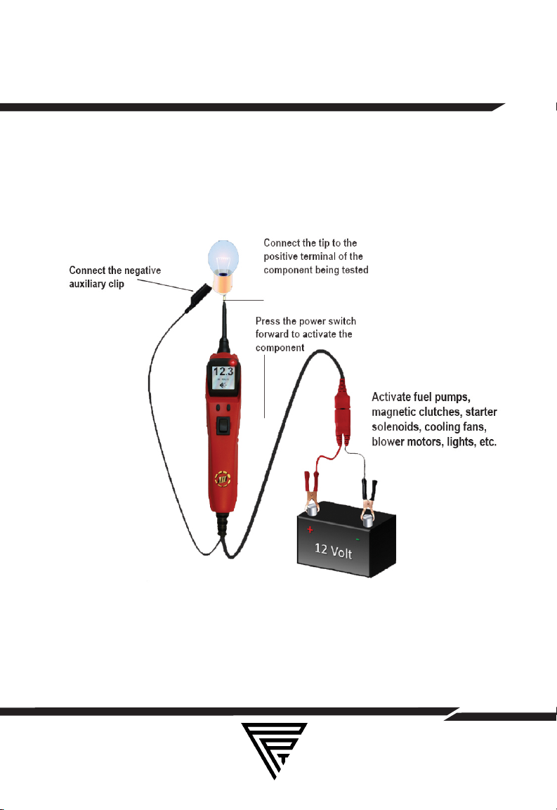
While the PP3EZ is in Voltmeter Mode and by using the Power
Probe tip in connection with the auxiliary ground lead, com-
ponents can be activated right in your hand, thereby testing
their function. Connect the negative auxiliary clip to the neg-
ative terminal or ground side of the component being tested.
Contact the probe to the positive terminal of the component,
the green negative sign “-“ LED indicator should light GREEN
indicating continuity through the component.
While keeping an eye on the green LED negative sign, quickly
depress and release the power switch forward (+). If the green
negative sign “-“ LED went out and the red positive sign “+”
came on, you may proceed with further activation. If the green
negative sign “-“ LED went o at that instant or if the circuit
breaker tripped, the Power Probe has been overloaded. This
could happen for the following reasons:
• The contact you are probing is a direct ground or negative
voltage.
• The component you are testing is short-circuited.
•The component is a very high current component (i.e., starter
motor).
If the circuit breaker is tripped, reset it by waiting for it to cool
down (15 sec.) and then depressing the reset button.
WWW.POWERPROBETEK.COM
11
ACTIVATING COMPONENTS IN HAND
WWW.POWERPROBETEK.COM
12
ACTIVATING COMPONENTS IN HAND
WWW.POWERPROBETEK.COM
13
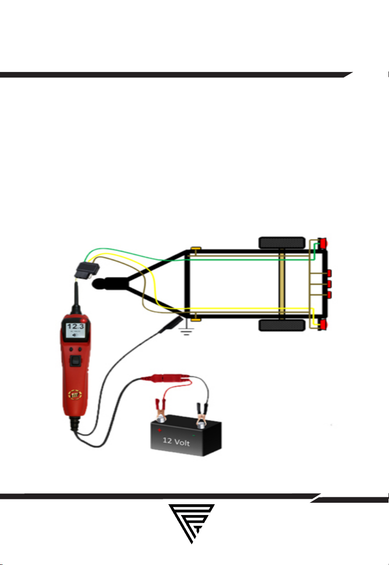
TRAILER LIGHT CONNECTIONS
1. Connect the PP3EZ to a good battery.
2.Clip the auxiliary ground clip to the trailer ground.
3. Probe the contacts at the jack and then apply voltage to
them. This lets you check the function and orientation of the
connector and trailer lights. If the circuit breaker tripped, that
contact is likely a ground. Reset the circuit breaker by letting
it cool down (15 sec.) and depressing the reset button until in
clicks into place.

WWW.POWERPROBETEK.COM
14
ACTIVATING COMPONENTS ON
VEHICLE
To activate components with positive (+) voltage: Contact
the probe tip to the positive terminal of the component, the
green negative sign “-” LED should light. Indicating continuity
to ground. While observing the green indicator, quickly de-
press and release the power switch forward (+). If the green
indicator went out and the red positive sign (+) LED came on,
you may proceed with further activation. If the green indica-
tor went o at that instant or if the circuit breaker tripped, the
Power Probe has been overloaded. This could happen for the
following reasons:
•The contact is a direct ground.
•The component is short-circuited.
•The component is a high current component (i.e., starter
motor).
If the circuit breaker tripped, reset it by allowing it to cool
down (15 sec.) and then depress the reset button.
Warning: Haphazardly applying voltage to certain circuits can
cause damage to a vehicle’s electronic components. There-
fore, it is strongly advised to use the vehicle manufacturer’s
schematic and diagnosing procedure while testing.

WWW.POWERPROBETEK.COM
15
ACTIVATING COMPONENTS ON
VEHICLE

WWW.POWERPROBETEK.COM
16
ACTIVATING COMPONENTS WITH
GROUND
Contact the probe tip to the negative terminal of the compo-
nent, the LED indicator should light RED. While observing red
positive sign “+” LED, quickly depress and release the power
switch rearward (-). If the red indicator went out and the green
negative sign (-) came on you may proceed with further ac-
tivation. If the green indicator went o at that instant or if the
circuit breaker tripped, the Power Probe has been overload-
ed. This could have happened for the following reasons:
• The contact is a direct positive voltage.
• The component is short-circuited.
• The component is a very high current component (i.e., starter
motor).
If the circuit breaker tripped, reset it by allowing it to cool
down (15 sec.) and then depress the reset button.
WARNING: With this function, if you are contacting a protected
circuit, a vehicle’s fuse can be blown or tripped if you apply
ground to it.

WWW.POWERPROBETEK.COM
17
ACTIVATING COMPONENTS WITH
GROUND

WWW.POWERPROBETEK.COM
18
CHECKING FOR BAD GROUNDS
Probe the suspected ground wire or contact with the probe
tip. Observe the green negative sign “-” LED. Depress the
power switch forward then release. If the green negative sign
“-” LED went out and the red positive sign “+” came on, this is
not a true ground.
If the circuit breaker tripped, this circuit is more than likely a
good ground. Keep in mind that high current components
such as starter motors will also trip the circuit breaker.
FOLLOWING AND LOCATING SHORT
CIRCUITS
In most cases a short circuit will appear by a fuse or a fusible
link blowing or an electrical protection device tripping (i.e.,
a circuit breaker). This is the best place to begin the search.
Remove the blown fuse from the fuse box. Use the Power
Probe tip to activate and energize each of the fuse contacts.
The contact which trips the PP3EZ circuit breaker is the short-
ed circuit. Take note of this wire’s identification code or color.
Follow the wire as far as you can along the wiring harness, for
instance if you are following a short in the brake light circuit
you may know that the wire must pass though the wiring
harness at the door sill. Locate the color-coded wire in the
harness and expose it. Probe through the insulation with the
Power Probe tip and depress the power switch forward to ac-
tivate and energize the wire. If the Power Probe circuit break-
er tripped you have verified the shorted wire. Cut the wire and
energize each end with the Power Probe tip. (continued)

WWW.POWERPROBETEK.COM
19
The wire end which trips the Power Probe circuit breaker
again is the shorted circuit and will lead you to the shorted
area. Follow the wire in the shorted direction and repeat this
process until the short is located. The Power Probe ECT3000
uses a wireless non-contact technique that guides you to the
short/open location.
FOLLOWING AND LOCATING SHORT
CIRCUITS
RED/GREEN POLARITY INDICATORS &
TONES
The “RED/GREEN Polarity Indicator” lights-up when the probe
tip voltage matches the battery voltage within ± 0.5 volts. This
means that if you contact a circuit that is not a good ground
or a good hot, you will see this instantly by the “RED/GREEN
Polarity Indicator” NOT lighting. The Audio Tone runs parallel
to the “RED/GREEN Polarity Indicator and will also NOT react
when contacting a circuit that does not match the battery volt-
age within ± 0.5 volts. This is a very useful function that auto-
matically alerts you of any excessive voltage drop in the circuit.
FLIP SCREEN FUNCTION
The PP3EZ has the adiitional ability to change the orientation
of the display screen. Press the right menu button to bring up
the menu, then use the left button to scroll to “FLIP SCREEN”
then press the right button again. The display screen will now
be inverted 180 degrees allowing the user to select either
display mode depending on the testing situation. Selecting
the “FLIP SCREEN” function again to restore the display to it’s
original orientation.

WWW.POWERPROBETEK.COM
20
MODES
The Power Probe 3EZ has been designed to work the same
as the previous Power Probe circuit testers. Using the ad-
vanced features and modes is optional. However, understand-
ing them will expand your diagnosing capabilities. The LCD
display indicates voltage levels of the circuit along with an
identifying symbol showing you what mode it is in. The addi-
tional features contain 5 new modes which give you specific
information about how the circuit is reacting.
The 5 Modes menu can be accessed by depressing the right
Menu button. Then press the left button to select the needed
test mode. Once the desired test mode is highlighted on the
menu screen, press the right Mode button to enter that test
mode.
Mode #1 Voltmeter Mode: While the PP3EZ is in “Voltmeter
Mode” and the probe tip is floating (not contacting a circuit),
the display will show “DC VOLTS.” If the audio tone is turned
on you will see a speaker symbol in the lower part of the dis-
play. Once you contact the probe tip to a circuit the LCD dis-
play will indicate the average voltage level of the circuit. The
red/green polarity indicator (See section Red/Green Polarity
Indicator and Audio Tone) will respond also, showing whether
the circuit is positive or negative. A secondary feature in this
mode is the peak to peak threshold detection and signal mon-
itoring. When contacting a signal generating circuit such as a
speaker wire with audio signals on it, the PP3EZ detects the
peak to peak signals and displays the peak to peak voltage
Table of contents
Languages:
Other Power Probe Measuring Instrument manuals


Popular Measuring Instrument manuals by other brands


PCB Piezotronics
PCB Piezotronics IMI SENSORS 66102APZ1 Installation and operating manual

Lovibond
Lovibond Photometer-System MD100 instruction manual

Leica Geosystems
Leica Geosystems Viva TPS Getting started guide

Onset
Onset U20-001-04-TI user manual

Stage6
Stage6 S6-4080/OR instructions

Davis Instruments
Davis Instruments Rain Collector instruction manual


