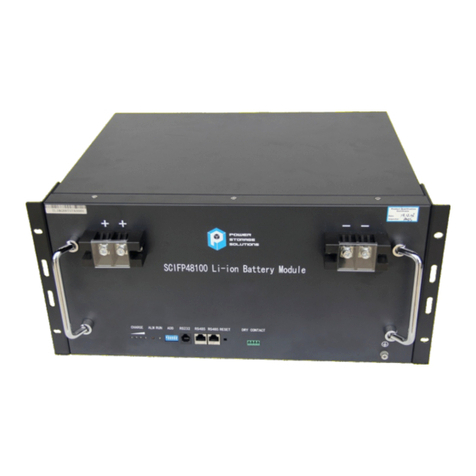
Power Storage Solutions 12MQ1200 User manual

Battery Installation,
Operation and
Maintenance Manual

Important
Please read this manual immediately upon receipt of battery before unpacking and installing. Failure to comply with these instructions will render any warranties null and
void. The term battery within this literature pertains to (1) 12-Volt battery unit consisting of (6) individual cells.
Receiving the Shipment
Carefully examine the battery shipment upon arrival for any signs of transit damage
and that it agrees with the materials list or packing slip. Be very careful not to
inadvertently discard any accessories contained in the packing material.
Batteries contain immobilized dilute sulfuric acid absorbed in the glass- mat
separators.
Use gloves appropriate for the electrical and chemical hazards when handling
broken or damaged containers in case of acid leakage.
Storage
Store 12MQ batteries in a dry, clean and preferably cool location.
Since the batteries are supplied charged, storage time is limited. In order to easily
charge the batteries after prolonged storage, it is advised not to store it more than:
6 months at ambient temperature no warmer than 77° F (25° C)
4 months at 86° F (30° C)
2 months at 104° F (40° C)
Give the battery a freshening charge before the end of the recommended storage
interval.
A refreshing charge shall be performed at 2.26 Volts per cell (VPC) at 77° F (25° C)
for 96 hours or until the charge current does not vary for a 3-hour period.
The necessity of a charge can also be determined by measuring the open circuit
voltage of a stored battery. (See Table 2)
Charging is advised if the voltage drops below 2.07 VPC.
Maximum total storage prior to installation is 2 years from date of shipment from
the factory to the customer. Freshening charges are required before the end of the
storage time period or more frequently, as noted above.
Failure to observe these conditions may result in greatly reduced capacity and
service life.
FAILURE TO CHARGE AS NOTED VOIDS THE BATTERY’S WARRANTY.
Installation
Install in clean, dry area. 12 MQ batteries release minimal amounts of gas during
normal operation (gas recombination efficiency ≥ 97%). The batteries can be
installed near the main equipment. Batteries must be installed in accordance with
federal, state and local law regulations and the manufacturer’s instructions.
Temperature
Avoid placing batteries in areas of high temperature or in direct sunlight. The
batteries will give their best performance and service life when operating at a
temperature between 68° F (20° C) and 77° F (25° C), however they are capable of
operating in a temperature range of -22° F (-30° C) to 122° F (50° C). Please
reference the charging float voltage section for more information regarding float
voltage adjustments for temperature variations. Reasonable precautions should be
taken to prevent continuous operation below -22° F (-30° C) or above 122° F (50° C).
Ventilation
Under normal conditions gas release is very low and natural ventilation is sufficient for
cooling purposes and the possibility of out-gassing. This enables Interstate
MQ
batteries to be used safely in close proximity to electronic equipment.
However, care must be taken to ensure adequate ventilation when placed in
cabinets. Batteries must not be placed in sealed cabinets.
Stowing
For proper installation, Interstate battery racks and cabinets are recommended.
If provided, intercell connector covers should be installed after completing the
intercell connections.
Attention: Unless otherwise noted, battery racks and cabinets should not be
transported with rigid intercell connectors in place.
Torque
The maximum torque load of intercell connector bolts (M6) is 60 in-lbs (6.8 N•m
+/- 5%). A loose connector can cause problems in charger adjustment,
erratic battery performance, possible damage to the battery and/or personal injury.
Handling
12MQ batteries are supplied in a charged condition
and are capable of extremely high short circuit
currents. Take care to avoid short-circuiting terminals
of opposite polarity.
Keep flames away
In case of accidental overcharge a flammable gas can leak
off the safety vent.
Discharge any possible static electricity from clothes by
touching an earth connected part.
Tools
Use tools with insulated handles.
Do not place or drop metal objects on the battery.
Remove rings, wristwatch and articles of clothing with metal parts
that may come into contact with the battery terminals.
California Proposition 65 Warning - Battery posts, terminals, and related accessories contain lead and lead compounds, chemicals known to the State of California to cause cancer and
reproductive harm. Wash hands after handling.

Cells in Parallel Strings
When using a constant voltage charger, ensure that the connections from the
charger at the end of each string have the same electrical resistance.
There is no theoretical limit on the number of strings that can be used in parallel.
However, there might be practical limits on the number of parallel strings such as
short circuit current limits, cable resistances and charger current limitations.
Charging
Float Voltage
The float/charge voltage is 2.265 VPC (+/- 0.015 V) at 77° F (25° C).
When the average ambient temperature deviates more than ± 9° F (5° C) from the
reference, it is necessary to adjust the float voltage as follows:
2.33 to 2.36 VPC at 32° F (0° C)
2.30 to 2.33 VPC at 50° F (10° C)
2.27 to 2.30 VPC at 68° F (20° C)
2.25 to 2.28 VPC at 77° F (25° C) (reference)
2.23 to 2.26 VPC at 86° F (30° C)
2.22 to 2.25 VPC at 95° F (35° C)
Due to the phenomena of gas recombination, a difference of ± 2% (earlier in float life
± 5% is common) for an individual cell voltage can be observed. However, the total
voltage of the battery shall be within the limits stated above.
Equalization Change
Periodic equalizing is not normally required to correct cell/unit imbalance.
Equalize charging should not be performed unless specifically recommended by
Power Storage Solutions. Please consult Power Storage Solutions before applying
and equalization change.
Ripple Current
Unacceptable levels of ripple current from the charger or the load can cause
permanent damage and a reduction in service life. It is recommended to limit the
continuous ripple current to the values of the Table 1 (in amperes).
Charging Current
The recommended charging method for 12 MQ batteries is current limited,
constant voltage charging. Refer to Table 1 for the current limits for each
battery model.
State of Charge
The battery state of charge can be determined approximately by measuring the
open circuit voltage after the battery has been at rest (off charge) for a minimum
of 24 hours at 77° F (25° C).
Discharging
End of Discharge Voltage
The end of discharge voltage must be limited to 1.60 VPC.
A protective system should be installed to prevent deep discharge.
Discharged Cells
MQ batteries must not be left in a depleted state after discharge. They
should be immediately recharged to a fully charged condition.
Failure to observe these conditions may result in greatly reduced service life
and unreliability.
Accidental Deep Discharge
When the battery is completely discharged, the sulfur from the dilute sulfuric acid
is completely absorbed in the plates and the remaining electrolyte consists only
of water.
At this point, the sulfation of the plates is at its maximum, considerably increasing
the cell’s internal resistance.
Important notice: This type of deep discharge will provoke a premature
deterioration of the battery and a noticeable effect on life expectancy.
The Effect of Temperature on Capacity
Correction factor of the capacity, according to temperature.
Maintenance and Records
12 MQ batteries are absorbed electrolyte, lead-acid type and need no water
addition. These batteries are equipped with self-resealing, flame-arresting safety
vents.
The containers and lids shall be kept dry and free from dust. Cleaning must be done
only with a damp cotton cloth. Check monthly that total voltage at battery terminals,
while on float, is (N x 2.25 to 2.28 V) for a temperature of 77° F (25° C), (where N is
the number of cells in the battery). Upon initial installation, the battery unit date
codes and installation date should be recorded. In addition, individual battery unit
and string voltages, as well as, unit ohmic values (if practical) should be taken and
retained.
Every 12 months, read, measure and record the following:
Individual battery unit and string voltages
Battery unit internal ohmic values
Intercell connection resistance
Ambient temperature in the vicinity of the battery and the temperature,
take at the battery string negative post.
Keep a record (both hard and soft copy) of all measured values, load test and any
maintenance issues.
An autonomy check can be carried out once or twice a year.
The above record taking is the absolute minimum to protect the warranty.
This data will be required for all warranty claims.
For temperature correction factors for use when load testing a
battery, please refer to the Temperature Correction factor tables
published in IEEE Standard 1188, latest version.

Note: End terminal position will depend upon number of units in row, ie., whether ODD or EVEN number.
UC: Unit center to center
RC: Row unit center to center
H
LONG
L
WSHORT
UC
Single row
configuration
(MQ models)
ROW
RC
Double row
configuration
(MQ models)
Intercell Connector Layout
Batteries come standard with a stainless steel hardware package; p/n 867500 (one package per battery). The
hardware package includes (2) each M6 x 1 x 16mm long bolts, flat washers and lock washers. Longer bolts are
available but must be specified at the time of order placement.
Optional Extras
* For run times under 15 minutes or end voltages less than 1.67, consult technical support for assistance.
Connectors and L-Terminals are RoHS compliant. L-Terminal
for multiple
cables
Power
Storage
Solutions
10490 Markison Road
Dallas, TX 75238
Toll Free 888.813.5049
pwrstoragesolutions.com
This manual suits for next models
5
Other Power Storage Solutions Camera Accessories manuals