Deutsch (Übersetzung der originalen anleitungen)
8
EN DE
ES IT FR PT NL RU FI SV NO DA PL CS SK SL HR HU RO BG EL AR TR HE LT LV ET
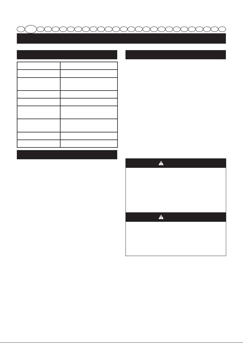
ANWENDUNGEN
Umgraben von Erdreich im Garten zur Vorbereitung
eines Saatbeets zur Bep anzung.
Flache Kultivierung zur Entfernung von Unkraut
EINSCHALTEN/AUSSCHALTEN DES KULTIVA-
TORS Siehe Abbildung 6
Einsetzen des akkus.
Stellen Sie sich hinter die Maschine. Die Zinken
müssen sich auf dem Boden benden und der
Arbeitsbereich muss gereinigt und frei von
Hindernissen sein.
Drücken Sie die Schalter-Sperre (5).
die Zinkenrotation zu starten.
auszuschalten.
VORBEREITUNG DES SAATBEETS Siehe Abbildung 7
im Garten umzugraben und ein Saatbeet zur Bep
anzung bzw. Aussaat vorzubereiten. Planen Sie im
so dass sie mit der Maschine auch noch kultivieren kön-
BITTE BEACHTEN:
beim ersten Durchlauf zu tief zu graben. Falls die
-
was schneller nach vorne bewegen oder bringen Sie
die Rad/ Zugstangen-Konstruktion an. Heben Sie den
nach schweren Regenfällen ein oder zwei Tage bis der
Boden wieder trocken ist.
ALLGEMEINES KULTIVIEREN Siehe Abbildung 8
Flaches Kultivieren mit einer Tiefe von weniger als 5
und dem Boden Sauerstoff zuzuführen ohne in der
Nähe liegende P anzenwurzeln zu verletzen. Dies sollte
wachsen kann und sich dadurch dann in den Zinken der
Maschine verfängt. Die beiden äußeren Zinkenblätter
Kultivierungsbreite zu erzielen. Zum Entfernen der zwei
äußeren Zinken:
Entfernen Sie den Akku.
an den Enden des Zinkenschafts.
Entfernen Sie die äußeren Zinkenblätter und
Filzscheiben vom Zinkenschaft.
Stecken Sie die Anhangstifte wieder in die
ZINKEN VON FREMDKÖRPERN BEFREIEN
Beim Betrieb kann ein Stein oder eine Wurzel in den
Zinken eingeklemmt werden. Es kann sich auch langes
Gras oder Unkraut um den Zinkenschaft wickeln.
Lösen Sie zum Reinigen der Zinken den Auslöser.
Trennen Sie den Kultivator vom Stromkreis und lösen
bzw. entfernen Sie Hindernisse von den Zinken oder
vom Schaft ab. Lesen Sie hierzu den Abschnitt Zinken
Entfernen und Anbringen in dieser Anleitung.
WARTUNG UND PFLEGE
WARNUNG
Verwenden Sie fürdieWartungnur Originalersatzteile.
Die Verwendung anderer Teile kann gefährlich sein
oder eine Beschädigung des Produkts verursachen.
WARNUNG
Tragen Sie beim Arbeiten mit dem Kultivator bzw.
bei Staubentwicklung immer eine Schutzbrille mit
Seitenschutz. Tragen Sie außerdem bei staubigen
Arbeiten eine Atemschutzmaske.
WARNUNG
Entfernen Sie zur Vermeidung schwerer Verletzungen
bei der Reinigung oder der Durchführung anderer
Wartungsarbeiten immer erst den Akku aus dem
Werkzeug.