Pottinger SYNKRO 4030 K/nova User manual

Nr. 99 9794.GB.60M.1
Mounting instructions
SYNKRO 4030 K/nova
(Type 9794 : + . . 01001)
SYNKRO 5030 K/nova
(Type 9795 : + . . 01001)
SYNKRO 6030 K/nova
(Type 9796 : + . . 01001)

Table of contents
SAFETY NOTES
Qualification ............................................................................................................................................. 3
Intended use............................................................................................................................................. 3
Before starting assembly..........................................................................................................................3
General safety instructions for assembly ................................................................................................. 3
Symbols used in the assembly instructions............................................................................................. 4
BOLT TIGHTENING TORQUES - WORKS STANDARD
Scope ....................................................................................................................................................... 6
ASSEMBLY INSTRUCTIONS
As delivered Synkro 4030......................................................................................................................... 7
As delivered Synkro 5030 / 6030 ............................................................................................................. 8
Remove packaging as example Syncro 4030.........................................................................................9
Remove left discs frame........................................................................................................................... 14
Fit central adjustment for right strut......................................................................................................... 18
Fit boundary discs to discs frame............................................................................................................ 22
Fit discs frames........................................................................................................................................ 24
Fitting discs frame (Synkro 5030 / 6030)..................................................................................................29
Fitting bracket (Synkro 5030 / 6030)........................................................................................................ 32
Fit central adjustment struts..................................................................................................................... 34
Fitting the packer roller mounting bracket for individual rollers............................................................... 37
Fitting the mounting bracket for double rollers........................................................................................39
Fit packer roller.........................................................................................................................................40
Final inspection ........................................................................................................................................ 44
Carry out trial run .....................................................................................................................................44
Before setting to work.............................................................................................................................. 44

- 3 -
SAFETY NOTES
General safety instructions for assembly
DANGER
Hazard of severe and life-threatening injuries due to pinching, pulling, squeezing of the whole body
and escaping high-pressure hydraulic fluid.
• Wear tight fitting clothing and personal protective equipment such as safety goggles, gloves, safety shoes and a
hard hat.
• The assembly work has to be carried out in exactly the same sequence as described in these instructions.
• Do not weld, cut, grind or drill the frame, axle or other supporting parts unless particularly specified.
• The mounting of the add-on equipment changes the overall weight of the machine and, depending on the equipment,
may change the outer dimensions. Be aware of the outer dimensions when driving on public roads. Place a sufficient
ballast load on the tractor. At least 20% of the overall weight has to rest on the front axle.
• Make sure that nobody stays between the tractor and the machine during assembly or coupling. When the point
of coupling is invisible from the place of the driver, make sure that a reversing assistant is available. Do only stay
between the tractor and the machine when both units do not move anymore and have been secured against rolling
away.
• Make sure that the support legs are set to the correct height and are secured as prescribed.
• Do not stay in way of high-pressure hydraulic fluid that may escape.
Qualification
• These assembly instructions are intended for qualified expert personnel only.
Intended use
• The intended use is described in the operating instructions of the machine. The installation of add-on equipment
will not change the intended use of the machine.
Before starting assembly
• Place the machine on a firm ground. Kill the tractor engine. Apply the hand brake. Pull the ignition key and put the
key away.
• Make sure that all moving parts do not move anymore (rotating parts may coast for a while). Make sure that neither
the tractor nor the machine can roll away.
• Secure the working area in such a way that other persons do not present a danger or are endangered.
• Observe the local accident prevention regulations.
• Observe the warning signs (pictograms) on the machine, even if they are not referred to in the assembly instructions.

- 4 -
1200_Symbolerklärung_EN
Symbols used in the assembly instructions
The „Waste basket“ shows that parts marked as such
canbe disposed of as they will not bereusedanymore.
The „Trolley“ shows that parts / components marked
as such may be reused and mounted later.
Trolley
Waste basket
The „Tractor“ indicates the direction of travel of the
machine in operation. This facilitates the identification
of machine parts on the illustrations.
The „Smiley“ shows that an assembly procedure
has been successfully completed, provided all steps
are been completed correctly and in the sequence
prescribed.
Tractor
Smiley
The following symbols are used in assembly instructions of Pöttinger.
Please memorize the meaning of the symbols.
If you find any symbol in the assembly instructions that is unknown to you or you are not sure about, please consult
these pages and read the meaning once again.
MeaningSymbol
The „Eye“ shows that specific points marked with a
frame need to be observed.
Eye
Components marked with a„Frame“ require particular
attention. Even groups of parts requiring specific
attention are marked with a frame. The action
required will be marked e.g. with a „Waste basket“,
an „Arrow“, etc.
Frames
The „Tube“ shows a point where sealing compound /
adhesive needs to be applied. The sealing compound
/ adhesive to be used is specified separately in a
text box.
Tube

- 5 -
1200_Symbolerklärung_EN
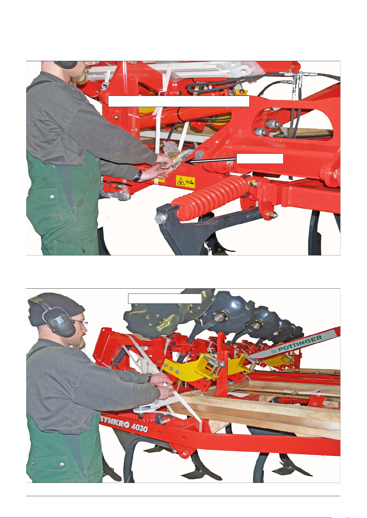
This arrow points at parts associated with a text box.
The part will be named in the text box or the assembly
will be described in detail. This arrow also marks the
relationship to illustrations or particular marked points
in the illustrations.
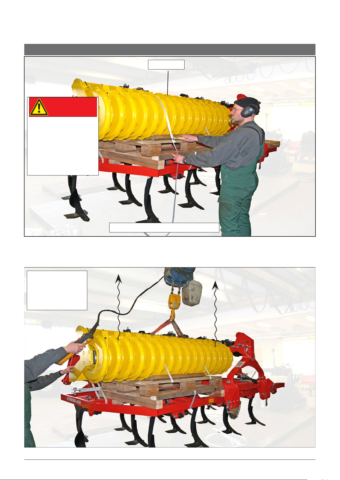
„Textboxes“containmaterialnumbers,denominations,
safety notes and assembly notes.
Text box Text box Text box
This arrow indicates the direction of motion or
rotation. In connection with tools, this arrow shows
the tightening or loosening direction of nuts and bolts.
Arrow 1
Arrow 2
This arrow shows the point where parts are to be
installed or bolts have to be mounted. For the sake
of clarity, not all parts are provided with these arrows,
e.g. when several bolts adjacent to each other have
to be mounted at the same time.
137
The „Item number“ designates a part. As the same
number is used in the parts list, the part can be
identified unambiguously.
Arrow 3
Item number
The „Book“shows thatfurtherimportantinformation to
be observed is included in the operating instructions.
Book
The „Tool“ shows that specific assembly procedures
need to be performed at this point of progress, e.g.
insertion of a spring pin or tightening of a screw. In
connection with „Arrow 2“, a specific direction of
rotation can be indicated. The illustration on the left
only shows some of the symbols used.
Tool
The „Grease gun“ indicates a point of lubrication,
grease nipple, plain bearing, etc. to be lubricated with
universal grease. Any other lubricant to be applied
will be indicated in a separate text box.
Grease gun
MeaningSymbol

- 6 -
1200_werksnorm_schraubenanzugsmomente_EN
BOLT TIGHTENING TORQUES - WORKS STANDARD
Scope
This works standard applies to all metric bolts for which no particular tightening torque has been specified in the
drawing/assembly instructions. The property class is shown on the bolt head.
• The specified values are nominal values and apply to a friction coefficient of the head of IJ = 0.14 and a thread
friction value of JJ = 0.125. Insignificant deviations of the tension force due to different friction coefficients may
occur. The specified values have to be observed within a tolerance of +10%.
• Based on the specified tightening torques and friction coefficients, the bolt material will be loaded with up to 90%
of the minimum yield limit according to DIN ISO 898.
• In the event of a special tightening torque having been specified, all screwed connections will have to be tightened
to the specified tightening torque using a torque wrench.
• The works standard will be in force as of May 1, 1995.
Thread Property class 8.8 Property class 10.9
Tightening torque in Nm Tension
force in N
Tightening torque in Nm Tension
force in N
M 4 3,1 4000 4,4 5700
M 5 6,2 6600 8,7 9300
M 6 10,5 9300 15 13000
M 8 25 17000 36 24000
M 10 50 27000 70 38000
M 12 86 39500 121 56000
M 14 135 54000 195 76000
M 16 215 75000 300 105000
M 20 410 117000 580 164000
M24 710 168000 1000 237000
M 30 1400 270000 2000 380000
M 8 x 1 27 18700 38 26500
M 10 x 1,25 53 29000 74 41000
M 12 x 1,25 95 44500 130 63000
M 14 x 1,5 150 60000 210 85000
M 16 x 1,5 230 81000 320 115000
M 20 x 1,5 460 134000 650 189000
M 24 x 2 780 188000 1090 265000

ASDELIVERED SYNKRO 4030
Packer rollers enclosed may vary from those presented in
these instructions. Doublerollers aredelivered on aseparate
pallet for packaging-related reasons. However installation
is carried out in the same manner in every case.
ASSEMBLY INSTRUCTIONS
- 7 -
9794.EN.60M.1

ASDELIVERED SYNKRO 5030 / 6030
- 8 -
9794.EN.60M.1

REMOVE PACKAGING AS EXAMPLE SYNCRO 4030
Remove packer roller transport safeguard.
DANGER
Danger of serious to fatal
injuries through falling
machine parts!
Transport safeguard
between packer roller and
pallet must still remain
intact!
Attach suitable lifting
device (lifting sling) to
middle of packer roller
and lift down from
machine.
Packer roller
- 9 -
9794.EN.60M.1

Remove transport safeguard from small parts bag.
Small parts bag.
Remove transport guard
- 10 -
9794.EN.60M.1

Remove accompanying struts.
Undo transport fixings and remove enclosed struts.
- 11 -
9794.EN.60M.1

Undo transport fixings and remove enclosed struts.
Remove cable ties – transport safeguard.
- 12 -
9794.EN.60M.1

Attach boundary disc
to suitable lifting device
(lifting sling).
Removepin
Remove boundary disc.
Carry out procedure similarly on both sides of machine.
- 13 -
9794.EN.60M.1

REMOVE LEFT DISCS FRAME
Discs frame
Attach suitable lifting device
(lifting sling) to discs on
discs frame as shown.
Undo transport fixings.
Keep individual removed parts handy.
- 14 -
9794.EN.60M.1

Undo transport fixings.
Keep individual removed parts handy.
Lift discs frame and carefully remove. Do not
damage paintwork!
- 15 -
9794.EN.60M.1

Remove struts as shown.
Keep individual removed parts handy.
Remove struts.
Remove struts as shown.
Keep individual removed parts handy.
Do not remove struts.
Removestruts.
Carry out procedure similarly on both sides of machine.
- 16 -
9794.EN.60M.1

Place discs frame in this position. This diagram shows right-side discs frame!
Lay out and sort contents of small parts bag.
This minimizes search time!.
- 17 -
9794.EN.60M.1

FIT CENTRAL ADJUSTMENT FOR RIGHT STRUT
Remove remaining packaging material.
Central adjustment strut.
Both struts are identical!
- 18 -
9794.EN.60M.1

Remove external stop.
Remove locking bolt and keep handy.
If no bolt is present, then it is in the small parts bag.
Remove pre-fitted bolt on other end of strut.
Einzelteile griffbereit halten.
- 19 -
9794.EN.60M.1

2. Move lever upward
1. Remove bolt
Reinsert bolt and tighten
Push strut in. Reinsert previously removed hex. bolt M 20
x 1.5 including sleeve.
- 20 -
9794.EN.60M.1
This manual suits for next models
2
Table of contents
Popular Tiller manuals by other brands

Racing
Racing RAC173PTIL-A user guide

Simplicity
Simplicity 5 H.P Roticul owner's manual

Amazone
Amazone KG 4002-2 Translation of the original operating instructions

White Outdoor Products
White Outdoor Products ROTO BOSS 510 217-310-190 owner's guide

Agrisem
Agrisem MAXIMULCH FOLDING 3 Series user manual

Craftsman
Craftsman 917.293480 owner's manual