Powerhorse M42411K User manual

M42411K
Owner’s Manual
Instructions for Installation/Set-up, Operation, Servicing, & Storage
Portable, Outdoor Use-Only, Gasoline Generator
Can be used to power individual appliances plugged directly into the generator’s outlets, or as a back-up
connection to a building’s power supply (via a professionally installed UL-approved transfer switch).
WARNING
READ and UNDERSTAND this manual completely before using the generator! Failure to properly set up,
operate, and maintain this generator could result in serious injury or death from carbon monoxide poisoning,
electric shock, fire/explosion, or burns. Generator has been shipped WITHOUT engine oil, Check the oil level
using the dipstick and add oil as needed. In particular, be aware of the following hazards:
CO Poisoning
Generators give off carbon monoxide, a poisonous gas that can kill you. You CANNOT smell it, see it, or taste it.
•ONLY run generator OUTDOORS and AWAY from building air intakes. NEVER run generator inside any enclosed or
semi-enclosed spaces, including homes, basements, garages, sheds, boxes, RVs, boats or pick-up truck beds. These
spaces can trap poisonous gases, EVEN if you run a fan or open windows.
•Install carbon monoxide alarms inside nearby structures/buildings (battery-operated, or plug-in with battery backup).
Electric shock / Electrocution
•High voltage electricity from generator can kill. DO NOT operate in wet locations. Be sure generator is properly
grounded. Use only UL-listed, outdoor-rated grounded extension cords of proper size.
•NEVER plug the generator directly into a wall outlet. ANY connection to a building’s electrical system MUST
ISOLATE THE GENERATOR FROM UTILITY POWER via a UL-approved transfer switch installed by a licensed
electrician. Otherwise, back feed from the generator into the power grid could kill utility workers.
Fire / Explosion
•DO NOT overload generator (per rated capacity), and OPERATE ONLY in an area with adequate cooling ventilation so
engine does not overheat. Exhaust can be extremely hot. Keep muffler at least 7 feet from all combustible objects.
•All fuels are flammable. Never fuel a running or hot engine. Never pump fuel directly into generator at gas station –use
approved container to transfer fuel. Ensure there are no fuel leaks, and keep sources of sparks and flames away.
•ALWAYS keep a fire extinguisher rated “ABC” nearby.
STOP!
CHOOSE THE RIGHT GENERATOR FOR YOUR NEEDS. See the “Power load Planning & Management” section
of this manual to determine your power load requirements and then compare to the generator’s rated capacity.
INSPECT COMPONENTS: Closely inspect to make sure no components are missing or damaged. See the “Unpacking
& Delivery Inspection” section for instructions on whom to contact to report missing or damaged parts.
ARRANGE FOR PROFESSIONAL INSTALLATION of a transfer switch if you will be connecting the generator to
your building’s electrical system. See the “Installation/Initial Set-Up” section for more information about this
requirement.
Any Questions, Comments, Problems, or Parts Orders
Call Powerhorse Product Support 1-866-443-2576
Item Number: 42411
Serial Number: _____________

Hazard Signal Word Definitions
2

Table of Contents
3
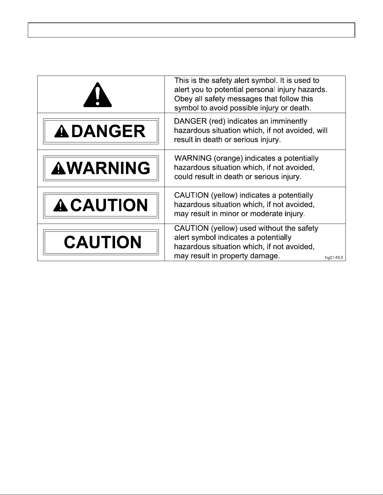
Hazard Signal Word Definitions ...................................................................................................2
About Your Generator ...................................................................................................................4
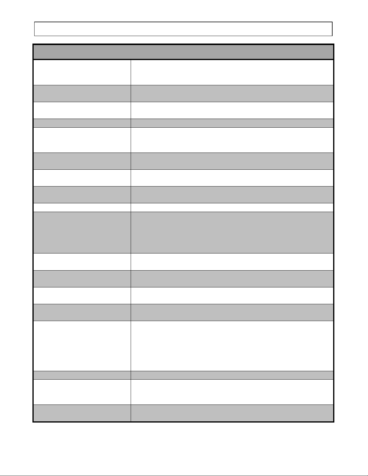
Specifications ...................................................................................................................................6
Safety Label Locations....................................................................................................................7
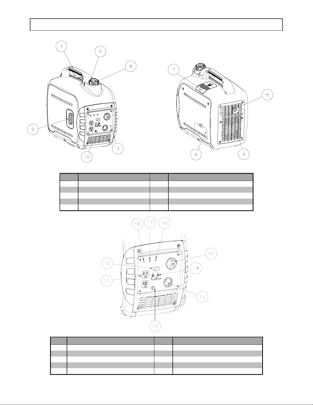
Machine Component Identification...............................................................................................9
Power Load Planning & Management..........................................................................................11
Installation / Initial Set-Up:
1. Unpacking & Delivery Inspection.......................................................................................... 14
2. Planning the Power Load........................................................................................................ 14
3. Set-up either as a BUILDING BACK-UP or PORTABLE Power Source ............................ 15
4. Selecting a Suitable Site......................................................................................................... 18
5. Grounding the Generator........................................................................................................ 20
Operation:
1. General Safety Rules for Operation ....................................................................................... 21
2. Preparing for Operation.......................................................................................................... 24
3. Starting the Generator............................................................................................................. 29
4. Checking Generator Output.................................................................................................... 31
5. Connecting Loads................................................................................................................... 32
6. Stopping the Engine ............................................................................................................... 32
7. AC Parallel Operation ............................................................................................................ 33
8. Storage & Exercise................................................................................................................. 35
Maintenance & Repair.................................................................................................................. 37
Troubleshooting............................................................................................................................. 47
Summary of Important Safety Information for Operation....................................................... 48
Generator Exploded View ............................................................................................................ 52
Generator Kit Exploded View...................................................................................................... 54
Limited Warranty ......................................................................................................................... 63
California Proposition 65 Information........................................................................................ 64

About Your Generator
4
Thank you for purchasing your Powerhorse portable generator!
About Your Generator
This engine-driven, portable generator is designed to provide up to its rated amount of electrical
power. (See specifications section of this manual for model specific ratings)
It can supply power:
1. As a portable power source. You can plug appliances directly into the generator’s electrical
outlets.
2. As a back-up, standby power source for a building. A licensed electrician can connect the
generator to your building’s electrical system via the installation of an UL-approved transfer
switch. (See the “Installation & Initial Set-up” section of this manual to learn more about
specific requirements and precautions relating to wiring the generator to your building’s electrical
system.)
You must select a generator adequately sized for your power needs. You need to determine the
power needs of all the appliances/tools you wish to power at the same time and choose a generator rated
to provide at least that power level. See the “Power Load Planning & Management” section of this
manual to determine your specific power load requirements and then compare them to this generator’s
rated capacity. You must not overload the generator. Overloading will cause damage to the generator
and attached electrical devices, and may also result in fire.
Be sure to read about site selection and grounding requirements for running this generator. More
detailed information can be found in the “Installation & Initial Set-up, Steps 4 & 5 of this manual.
Contact Powerhorse Product Support at 1-866-443-2576 with questions about optional accessories
or to order.
Read this Manual
WARNING
Improper use or maintenance of this generator can result in serious injury or death from
carbon monoxide poisoning, electric shock/electrocution, fire/explosion, or burns.
Read this manual completely before using the generator and follow all instructions and
safety rules.
You must follow all instructions and safety precautions presented throughout this manual. A summary
of important safety information can be found at the end of the manual. Keep this manual for reference
and review.
Proper preparation, operation, and maintenance will result in operator safety, as well as best
performance and long life of the generator. For detailed engine operation and maintenance information,
always refer to the engine Owner’s Manual furnished with the generator.
Powerhorse is constantly improving its products. The specifications outlined herein are subject to
change without prior notice or obligation. The purchaser and/or user shall assume liability for any
modification and/or alterations of this equipment from original design and manufacture.

About Your Generator
5
Before using, the user shall determine the suitability of this product for its intended use and assumes
liability therein.
Contact Powerhorse Product Support at 1-866-443-2576 for any questions about the appropriate
use of this generator.
Warranty Registration
Please fill in the warranty registration information in the back of this manual and have it on hand when
you call in on a warranty claim or replacement parts.
ATTENTION:
All Rental Companies and Private Owners who loan this
equipment to others!
All persons to whom you rent/loan this generator must have access to and read this manual.
Keep this owner’s manual with the generator at all times and advise all persons who will
operate the machine to read it. You must also provide personal instruction on how to safely
operate the generator and remain available to answer any questions a renter/borrower might
have.

Specifications
6
Item Number
#42411
Maximum Output
2000 Watts (W)
Continuous Output
1600 Watts (W)
Voltage
120 Volt (V)
Phase
Single phase
Frequency
60 Hertz (Hz)
Power Factor
1.0 p.f.
Engine
Powerhorse 79cc
Engine Speed
3,600 –5,000 RPM (with ESC button OFF)
Fuel Type
Non-leaded automobile gasoline
Fuel Capacity
1.1 US gallons (4.0L)
Oil Type
10W-30 (API Service SE type or higher)
Oil Capacity
0.42 US quarts (0.35L)
Noise Level
52 dBA ~ 61 dBA @ 7 meters
Starting Method
Recoil
Dimensions
Length
19.64”
Width
11.22”
Height
17.91”
Dry Weight
46 lbs.
Any Questions, Comments, Problems, or Parts Orders
Call Powerhorse Product Support 1-866-443-2576

Safety Label Locations
7
Always make sure safety labels are in place and in good condition. If a safety label is missing
or not legible, order new labels or unsafe operation could result.
To order replacement safety labels, call Powerhorse Product Support at 1-866-443-2576.
Ref. No.
Part #
Description
Qty
1
790858
Overfill & Spark Decal
1
2
790855
Exhaust Decal
1
3
790857
Name Plate
1
4
790854
EPA Decal
1
5
790908
Oil Fill Decal
1
6
790852
Burn Hazard Decal
1
7
790853
CPSC Decal
1
8
790856
Improper Connection Decal
1
N/A
790933
Small Powerhorse Decal (recoil side)
1
N/A
790859
Large Powerhorse Decal
1
N/A
796449
Powerhorse Decal (front)
1

Safety Label Locations
8
1
2
3
4
5
6
7
8

Machine Component Identification
9
Ref.
Description
Ref.
Description
1
Carrying Handle
6
Oil Fill Cover with Screw
2
Recoil Starter
7
Spark Plug Maintenance Cover
3
Control Panel
8
Muffler
4
Fuel Tank Cap
9
Hot Air Discharge
5
Fuel Tank Cap Air Vent Knob
10
Cool Air Intake
Ref.
Description
Ref.
Description
10
ESC Button (Engine Smart Control)
15
Engine OFF/RUN/CHOKE control
11
120Volt 20 Amp Duplex Receptacles
16
Output Indicator Light (Green)
12
Grounding Post
17
Overload Indicator Light (Red)
13
120Volt 30 Amp Locking Receptacle
18
Low Oil Warning Indicator Light (Red)
14
Parallel Operation Outlets

10
REFERENCE GUIDE
Reference 1 –Carrying
Handle
Provides a means for moving and lifting the generator. Grasp the
handle firmly when pulling the recoil starter grip so the generator
does not fall over.
Reference 2 –Recoil Starter
Grip
Grasp firmly when starting engine to engage engine cranking.
Reference 3 –Control Panel
An electrical device that contains receptacles, switches and other
electrical devices.
Reference 4 –Fuel Tank Cap
The fuel tank cap seals the fuel in the tank.
Reference 5 –Fuel Tank Cap
Air Vent Knob
The fuel tank cap air vent knob must be in the ON position for the
generator to run. After the generator has cooled, turn the fuel
tank cap air vent knob to the OFF position to reduce leakage.
Reference 6 –Oil Fill Cover
and Port
Located behind the oil fill cover. Allows for adding the oil and
checking the oil level.
Reference 7 –Spark Plug
Maintenance Cover
Cover that allows access to spark plug.
Reference 8 –Muffler
An acoustic device installed onto the exhaust system that is
designed to reduce noise. The outlet includes a spark arrester.
Reference 9 –Louver
Opening in the casing for ventilation.
Reference 10 –ESC Button
With the Engine Smart Control button ON the generator will
automatically reduce the engine speed depending on the size of
the load. This will result in better fuel consumption and less
noise. With the Engine Smart Control button OFF the engine runs
at full RPM regardless if a load is connected or not.
Reference 11 –Duplex
Receptacles (NEMA 5-20R)
Electrical device able to accept AC 120V 15A or 20A plugs
(NEMA 5-15P or 5-20P)
Reference 12 –Grounding
Post
Means to connect the generator to a ground wire.
Reference 13 –Locking
Receptacles (NEMA L5-30R)
Electrical device able to accept AC 120V 30A locking plugs
(NEMA L5-30P)
Reference 14 –Parallel
Operation Outlets
This is the terminal for connecting two Powerhorse Inverter
Generators using special cables.
Reference 15 –Engine
OFF/RUN/CHOKE control
This switch has the following positions:
OFF - Stops the engine and closes the fuel valve.
RUN –Running position; opens the fuel valve and allows a warm
engine to be started, choke is off.
CHOKE –Starting position; opens the fuel valve and turns choke
on to start a cold engine.
Reference 16 –Output Light
Illuminates (green) when the generator starts and produces power.
Reference 17 –Overload
Light
Illuminates (red) when overload of any connected device is
detected, the inverter control unit overheats or AC output voltage
rises. The engine also stops and Output Light goes off.
Reference 18 –Low Oil
Warning Light
Illuminates (red) when oil falls below the lower level and the
engine stops automatically.

Power Load Planning & Management
11
WARNING
NEVER exceed the rated wattage capacity of your generator.
OVERLOADING may cause SERIOUS DAMAGE to the generator and
attached electrical devices, and may result in fire.
Your generator MUST BE SIZED PROPERLY to provide both the running and starting (surge)
wattage of the devices you will be powering. Before using your generator, determine the running
and starting wattage requirements of all the electrical devices you will be powering simultaneously.
The sum of the running and starting wattages of the devices being powered must not exceed the
continuous output rating of your generator. (The continuous output rating of your generator is listed
in the “Specifications” section of this manual.) Note that:
•Devices without electric motors such as light bulbs, radios, and televisions have the same
running and starting wattage.
•Devices with electric motors such as refrigerators, compressors, and hand tools typically
require a starting wattage that is 3 to 5 times greater than the running wattage.
The running and starting wattage requirements are often listed on a device’s nameplate. If wattage
is not given on the device’s nameplate, the wattage may be calculated by multiplying the nameplate
voltage by nameplate amperage, Watts = Volts X Amps.
Example conversion to watts:
120 Volts X 5 Amps = 600 Watts
If only the running voltage is given on the nameplate for a device with an electric motor, the starting
wattage can be approximated to be three to five times the running wattage.
Estimates for the running wattage requirements for common devices are listed in Table 1 below.
Guidance for starting wattages is provided in the table’s footnotes.
Table 1
Device
Running Watts
(Continuous)
Starting Watts
(Surge)
10in. Table Saw
1800
4500
7-1/4in. Circular Saw
1400
2300
8in. Bench Grinder
1400
2500
Air Conditioner - Central (24,000 BTU)
3800
4950
Air Conditioner - RV (13,500 BTU)
1500
3000
Air Conditioner - Window (10,000 BTU)
1200
2200
Battery Charger: 100 Amp with 300 Amp Boost
2400
7800
Battery Charger: 15 Amp
380
-
Battery Charger: 60 Amp with 250 Amp Boost
1500
5750
Belt Sander
1200
2400
Ceiling Fan
800
1200
Clock Radio
100
-
Clothes Dryer (electric)
1800
5750

Power Load Planning & Management (cont’d)
12
Device
Running Watts
(Continuous)
Starting Watts
(Surge)
Clothes Dryer (gas)
700
1200
Clothes Washer
1150
2300
Coffee Maker
1750
-
Deep Freezer
700
1000
Desktop Computer w/ 17" monitor
800
-
Dishwasher (Hot Dry)
1500
1500
Drill: 1/2in., 5.4 Amps
600
900
Drill: 3/8in., 4 Amps
440
600
DVD/CD Player
100
-
Electric Fence: 25 Miles
2500
-
Electric Fry Pan
1300
-
Electric Range: 8in. Element
2100
-
Furnace Fan (Gas or fuel oil): 1/2 HP
875
2350
Furnace Fan (Gas or fuel oil): 1/4 HP
600
1000
Furnace Fan (Gas or fuel oil): 1/8 HP
300
500
Garage Door Opener
750
1200
Hair Dryer
1250
-
Hot Plate
2100
-
Inkjet Printer
80
-
Iron
1200
-
Laser Printer
950
-
Lights (Ten 75 Watt light bulbs)
750
-
Microwave Oven 1000W
1000
-
Milk Cooler
1100
1800
Milker (Vacuum Pump): 2 HP
1000
2300
Miter Saw - 10"
1650
2400
Oscillating Fan
200
400
Portable Heater (Kerosene, Diesel: 150,000 BTU
625
1000
Pressure Washer: 1 HP
1200
3600
Quartz Halogen Work light
1000
-
Reciprocating Saw
1200
2000
Refrigerator Freezer
700
1500
Security System
500
-
Space Heater
1800
-
Stereo Receiver
450
-
Sump Pump: 1/2 HP
1050
2150
Sump Pump: 1/3 HP
800
1300
Television 27"
500
-
VCR
100
-
Water Heater (Electric 40gal)
4000
-
Water Well Pump (1/3hp 220v)
1000
2000
(a) Hard-starting motors require 3-5 times the rated running watts
(b) For extremely hard to start loads such as air conditioners and air compressors, consult the equipment dealer to
determine maximum wattage

Power Load Planning & Management (cont’d)
13
To calculate the running and starting wattage requirements for the devices you will be
powering, follow these steps:
1. Make a list of all electrical devices you will be powering at the same time with the generator.
2. List the greater of the running or starting wattage next to each device as obtained from the
devices’ nameplate or Table 1. If only the running wattage for a device with an electric
motor is known, the starting wattage can be estimated to be at least 3 times the running
wattage.
3. Add the wattages for all devices on your list. This total must be lower than the continuous
output rating of your generator.
Example:
Device to be Powered
Greater of
Starting/Running Wattage
Light Bulbs (10 –75 watt)
750 W
Refrigerator Freezer
1500 W
Microwave Oven 1000W
1000 W
Air Conditioner, Window (10,000 BTU)
2200 W
Sump pump (1/3 hp)
1300 W
Total
6750W
In this example, the generator must have a continuous output of at least 6750 watts in order to
power all of the devices simultaneously.
The overload indicator light 1 comes on when the total wattage exceeds the generators
capability. If that happens, proceed as follows:
1.Turn off any connected electric devices and stop the generator.
2.Reduce the total wattage of connected electric devices within the rated output.
3.Check for blockages in the cool air intake (louver) and around the control unit. If any
blockages are found remove.
4.After checking, restart the generator.
You can increase the number of devices your generator can power by staggering the load on the
generator. For example, you could alternately power your refrigerator and air conditioner for
limited periods of time -- powering only one of the devices at a time and never powering both at the
same time.
STAGGERING LOADS

Installation / Initial Set-Up
14
There are a number of important steps required to set up your generator for initial use. These
steps are:
Steps for Installation / Initial Set-Up
1. Unpacking & delivery inspection.
2. Planning the power load to stay within the generator’s rated
capacity.
3. Setting up generator for the type of power generation you need:
a. portable power source, or
b. connected to a building as a back-up power source.
4. Selecting a site for using the generator.
5. Grounding.
Each of these steps is discussed in detail below:
1. Unpacking & Delivery Inspection
You should inspect the generator immediately after you receive delivery.
See the “Machine Component Identification” section of this manual for a
diagram of the generator and its components.
•If you are missing or have damaged components, contact Product Support at 1-866-443-2576.
2. Planning the Power Load
Plan your power load so that you do not exceed the generator’s rated capacity.
See the “Power Load Planning & Management” section of this manual to review how to plan and
manage power loads for the generator.
Generator
Parallel Cable Kit
Part # 791456
Funnel
Part # 791453
Flat Head
Screw Driver
Part # 791455
Spark Plug Wrench
and Handle Bar
Part # 791454

Installation / Initial Set-Up
15
3. Set-up either as a BUILDING BACK-UP or PORTABLE Power Source
This generator is designed to provide up to its rated amount of electrical power. It can supply electricity
in two ways:
1. As a back-up, standby power source for a building. For this application, you must arrange for a
licensed electrician to connect the generator to your building’s electrical system via the installation
of an UL-approved transfer switch. The transfer switch must be installed in accordance with
building electrical code and guidelines supplied by your power company.
2. As a portable power source. You can plug appliances or tools directly into the generator’s
electrical outlets.
Specific requirements for each are given below.
Note: Regardless of whether you use your generator as a back-up power source connected to a
building or as a portable power source, you must not overload the generator. Overloading may
cause serious damage to the generator and attached electrical devices.
Using as a
Back-up Power
Source for a
Building
Contact a licensed electrician to install an UL-approved transfer switch if you
want to use your generator as a back-up power source for a building.
What does a transfer switch do? It:
a) Safely connects the generator to your building’s electrical system by
isolating your generator from your utility company’s power lines, AND
b) Connects your generator to a critical subset of your building’s circuits that
are needed for emergency power needs.
If your generator will be connected to your building’s electrical system, it MUST
ALWAYS be isolated from the utility power grid with a UL-approved transfer
switch installed by a licensed electrician in compliance with all applicable
building and electrical codes, and in accordance with guidelines supplied by your
power company.
DANGER:
A transfer switch must be installed in order to isolate your generator
from the utility power grid. If your generator is NOT properly isolated
from the utility system, serious hazards will arise:
When your generator is running, it’s output will back feed into the
utility power line and transformer that are normally used to provide
you with power. The transformer will step up the current to the

Installation / Initial Set-Up
16
normal line voltage. An unsuspecting utility line worker working on
what he thinks is a deactivated line could be electrocuted.
If your generator is connected (running or not) when utility power is
restored, your generator will be destroyed. It could also explode or
cause fire.
In addition to isolating your generator from the utility system, the transfer switch
connects your generator to a limited set of circuits in your building that have been
chosen as critical to operate during a power outage.
The generator may not power your entire home -- you must work with the
installing electrician to determine which devices/appliances you wish to power
during an outage. The electrician can help you determine which circuits and
devices can be powered simultaneously without overloading the generator.
(See the previous section of this manual entitled “Power Load Planning &
Management” for more information on load application and selection.)
Using as a
Portable Power
Source
When using the generator as a portable power source, you can plug electric
devices and appliances directly into the generator’s electrical outlets.
There are different kinds of electrical outlets on your generator:
1. 120 Volt, 20 Amp duplex straight-blade receptacles (NEMA 5-20R
duplex receptacle compatible with NEMA 5-20P or 5-15P mating plugs).
2. 120 Volt, 30 Amp locking receptacle (NEMA L5-30R receptacle
compatible with NEMA L5-30P mating plug).
1. Make sure you plug each electrical device/appliance into the correct
generator outlet based on the device’s plug configuration and
voltage/amperage rating. Never exceed the amperage rating of an outlet.
2. Extension cords may be used to power devices that are located at a
distance from the generator. However, use only UL-listed, outdoor-rated,
grounded extension cords of the proper size. Use Table 2 below to choose
an adequately sized extension cord according to the amperage of the
device being used and the length of the cord.
Table 2
Current/Power
Maximum Extension Cord
Length and Size (AWG)
Current At Full Load
(Amps)
0-25 ft.
25-50 ft.
50-100 ft.
100-150 ft.
6
18 ga.
16 ga.
14 ga.
12 ga.
8
18 ga.
16 ga.
12 ga.
10 ga.
10
18 ga.
14 ga.
12 ga.
10 ga.
12
16 ga.
14 ga.
10 ga.
8 ga.
14
16 ga.
12 ga.
10 ga.
8 ga.
16
16 ga.
12 ga.
10 ga.
8 ga.
18
14 ga.
12 ga.
8 ga.
8 ga.

Installation / Initial Set-Up
17
WARNING:
Use of under sized extension cords can cause electric shock, fire, or
damage to connected devices.
3. All extension and appliance cords must be in good condition and not worn,
bare, frayed, or otherwise damaged.
WARNING:
Use of damaged electric cords can cause electric shock or fire.
Note: If an extension cord becomes hot to the touch, it is overloaded or
damaged and must be replaced.
Northern Tool is NOT responsible for damage or injury resulting from customer
use of inadequate extension cords.

Installation / Initial Set-Up
18
4. Select a Suitable Site
Before using the generator, you must select a suitable OUTDOOR location for installation and
operation. This location should meet all of the criteria listed below.
WARNING:
You must choose a suitable site for operating your generator to avoid equipment damage
and/or injury and possible death from carbon monoxide poisoning, electric shock, or fire.
Choose a site that meets all of the criteria specified.
Dry, level surface
The generator should be positioned on a dry, firm, level surface.
Ensure that the generator sits level and will not slide or shift during operation.
If applicable, block the generator’s wheels to prevent sliding and shifting.
Outdoors only –
dangerous carbon
monoxide exhaust
WARNING: Carbon monoxide poisoning hazard
The exhaust from your generator contains carbon monoxide (CO), a
poisonous gas that can kill. You cannot smell it, see it, or taste it.
Carbon monoxide exhaust is given off whether you are using gasoline,
natural gas, or propane as the fuel source to power the generator.
Follow the directions below for choosing a location to operate your
generator in order to avoid carbon monoxide poisoning.
The location you choose to operate the generator must be OUTDOORS
and away from all air intakes:
•Never run the generator inside any closed or semi-enclosed spaces (even if
outdoors), including homes, garages, basements, sheds, or boxes. These
spaces can trap poisonous gases, even if you run a fan or open windows.
•Never place the generator immediately adjacent to a building or other
structure –allow at least 7 feet clearance.
•Place the generator so that the exhaust fumes will not be directed towards
people or building air intakes.
•Ensure that working, battery-operated or battery back-up carbon monoxide
alarms are used in any dwelling/structure that is in close proximity to the
running generator.
•Note that this generator is NOT designed or approved for use in vehicles
or marine applications. Never run the generator inside RVs or other
vehicles, on boats, or on pick-up truck beds.
WARNING:
Never attempt to attach ductwork to the muffler system to allow for
installation inside an enclosure. This could cause hot air deflection,
heat build-up, and increased exhaust back-pressure, resulting in
possible exhaust leakage or damage to the generator.

Installation / Initial Set-Up
19
Adequate cooling
ventilation
The generator needs adequate, unobstructed flow of air to allow for
proper cooling of engine and generator head.
WARNING:
Heat build-up from inadequate ventilation can result in fire, posing a
serious risk to nearby persons and structures.
•Situate so there is adequate clearance around generator to allow for
cooling airflow so that heat does not build up.
•Never place the generator immediately adjacent to a building or other
structure –allow at least a 7’ clearance.
•Do not run the generator in close proximity to other heat-generating
equipment, such as another generator. The combined heat that is
generated may raise air temperature in the immediate area and there will
not be adequate cooling ventilation.
•Do not allow debris to accumulate and block airflow.
•Do not operate with a tarp, blanket, or cover surrounding the generator.
No wet conditions
Choose a location where the generator will NOT be exposed to rain,
snow, or direct sunlight. Exposure to water can cause electric shock.
You may operate the generator under an outdoor, canopy-like structure of
heat-resistant material that is open on all sides. Make sure that all parts of
canopy are at least 7’ from exhaust, and allow for adequate clearance above
generator so that heat does not build up.
Hot exhaust
clearance
The exhaust gas from your generator is extremely hot and can cause
combustible materials to catch on fire.
•Make sure your generator’s exhaust system is at least 7 feet from all
combustible materials and buildings/structures.
•Equip the engine with a spark arrester if the generator will be used near
any ignitable forest, brush, or grassy land. (See the “Specifications”
section of this manual to determine if your generator is already equipped.)
Make sure you comply with applicable local, state, and federal codes.
•Keep a fire extinguisher rated “ABC” nearby. Keep it properly charged
and be familiar with its use.
Away from
dust/dirt
Do not use the generator in extremely dusty or dirty conditions.
Excessive dust and dirt can cause premature failure of the machine.
Hearing
protection
Generators can produce noise levels of up to 95 dB in close proximity,
which can be dangerous to human hearing with prolonged exposure.
Hearing protection may be required for persons working within 15-20 feet of
the running generator for an extended period of time.
WARNING:
Never attempt to attach ductwork to the muffler system to lower noise
levels. This could cause hot air deflection, heat build-up, and
increased exhaust back-pressure, resulting in possible exhaust leakage
or damage to the generator.

Installation / Initial Set-Up
20
5. Grounding the Generator
Always ensure the generator is properly grounded to prevent electrical shock.
You must always ground the generator by the following method when using the generator as a
portable electrical source:
1) Drive a 3/4” or 1” copper pipe or rod into the ground close to the generator. The pipe/rod
must penetrate moist earth –the depth required will be dictated by local soil conditions.
Consult with an electrician.
2) Connect an approved ground clamp to the pipe.
3) Run a 10 or 8 gauge wire from the clamp to the generator grounding post located on the
electrical panel.
4) Do not connect the generator grounding post to a water pipe or a ground used by a radio
system.
If a licensed electrician installs the generator with a connection to your building’s electrical circuit
for use as a back-up power system, grounding may alternatively be completed through the
building’s grounding system. Ask your electrician. If the generator is not grounded through your
building’s electrical system, follow the procedure above.
WARNING:
Operating the generator when it is not properly grounded can result in electrical shock.
10 or 8 Ga. wire
Copper Pipe/Rod
Grounding Post
Ground
This manual suits for next models
1
Table of contents
Other Powerhorse Portable Generator manuals

Powerhorse
Powerhorse 74006 User manual

Powerhorse
Powerhorse 83171 User manual

Powerhorse
Powerhorse M792220G.7 User manual

Powerhorse
Powerhorse M799215B.1 User manual

Powerhorse
Powerhorse M166114H User manual

Powerhorse
Powerhorse M166112B User manual

Powerhorse
Powerhorse M799215D.1 User manual

Powerhorse
Powerhorse 750134 User manual

Powerhorse
Powerhorse M792220G.5 User manual

Powerhorse
Powerhorse M166112F.2 User manual