manuals.online logo
Brands
  1. Home
  2. •
  3. Brands
  4. •
  5. Powermatic
  6. •
  7. Outdoor Light
  8. •
  9. Powermatic 6294924 User manual

Powermatic 6294924 User manual

Powermatic
427 New Sanford Road
LaVergne, Tennessee 37086 Document No. M-6294924
Ph.: 800-274-6848 Edition 1 04/2020
www.powermatic.com Copyright © 2020 Powermatic, a division of JPW Industries
#6294924, LED lamp with PM2014 bracket
WARNING: This product can expose you to chemicals including lead which is known to the State of California to cause
cancer and birth defects or other reproductive harm. For more information go to http://www.p65warnings.ca.gov.
WARNING: Drilling, sawing, sanding or machining wood products generates wood dust and other substances known to
the State of California to cause cancer. Avoid inhaling dust generated from wood products or use a dust mask or other
safeguards for personal protection. Wood products emit chemicals known to the State of California to cause birth defects or
other reproductive harm. For more information go to http://www.p65warnings.ca.gov/wood.
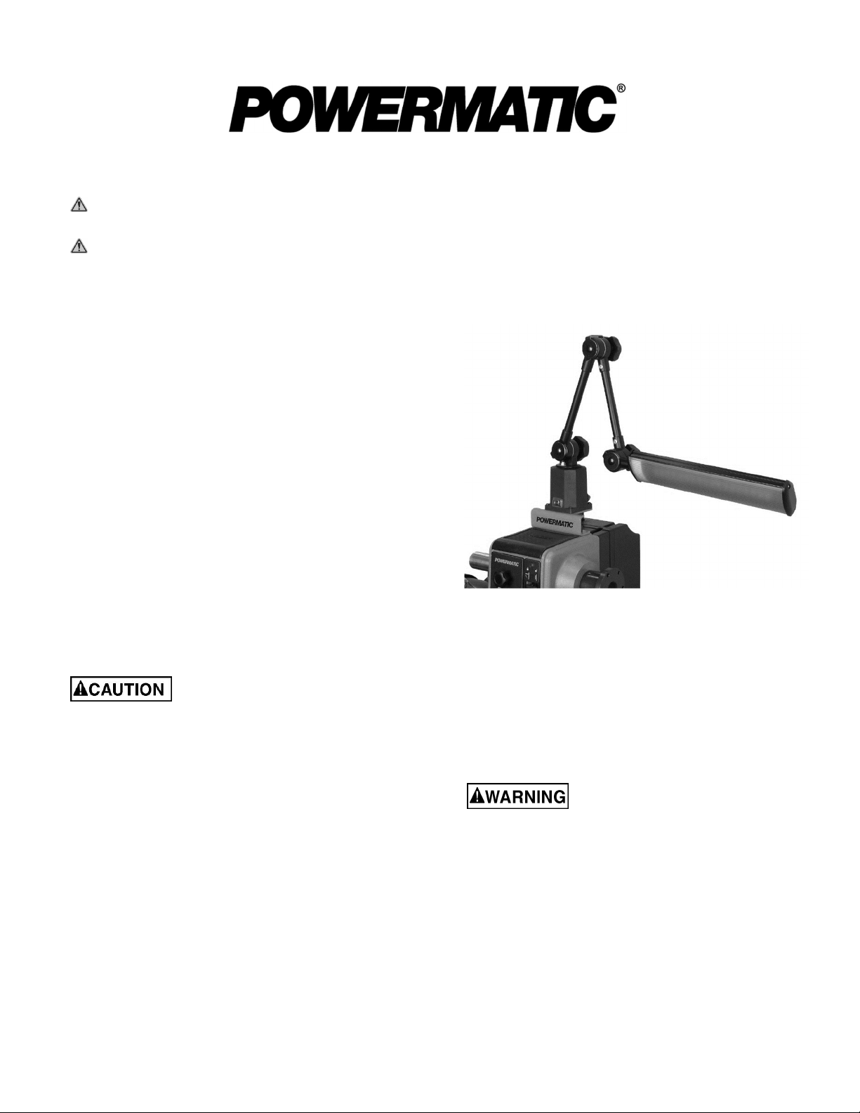
This accessory, when mounted to the bracket, is designed
for use with the Powermatic model PM2014 Lathe.
Contents of container:
1 LED lamp
1Mounting bracket
2 Socket head cap screws M12
4 Pan head screws M4
1 Instruction sheet
Assembly and operation
See Figure 1.
1. Mount the bracket to the two threaded holes atop the
lathe head with the socket head screws, and tighten.
2. Mount the lamp to the bracket with the four pan head
screws, and tighten.
Loosen hand knobs to adjust lamp position. Tighten knobs
to secure in position. The LED head can be rotated on its
own axis until it contacts the stop pin.
Before turning on lathe, make sure
spinning workpiece will not contact lamp. Ensure that
hand knobs are tight to prevent lamp from migrating
into workpiece during operation.
GROUNDING INSTRUCTIONS
This tool must be grounded. In the event of a malfunction
or breakdown, grounding provides a path of least
resistance for electric current to reduce the risk of electric
shock. This tool is equipped with an electric cord having an
equipment-grounding conductor and a grounding plug. The
plug must be plugged into a matching outlet that is properly
installed and grounded in accordance with all local codes
and ordinances.
Figure 1
Do not modify the plug provided - if it will not fit the outlet,
have the proper outlet installed by a qualified electrician.
Improper connection of the equipment-grounding
conductor can result in a risk of electric shock.
The conductor with insulation having an outer surface that
is green with or without yellow stripes is the equipment-
grounding conductor. If repair or replacement of the electric
cord or plug is necessary, do not connect the equipment-
grounding conductor to a live terminal.
Check with a qualified electrician or
service personnel if the grounding instructions are not
completely understood, or if in doubt as to whether the
tool is properly grounded. Failure to comply may
cause serious or fatal injury.
Use only 3-wire extension cords that have 3-prong
grounding plugs and 3-pole receptacles that accept the
tool's plug.
(continued)

2

Repair or replace damaged or worn cord immediately.
This tool is for use on a nominal 120-V circuit, and has a
grounded plug that looks like the plug illustrated in sketch
A in Figure 2. A temporary adaptor that looks like the
adaptor illustrated in sketches B and C may be used to
connect this plug to a 2-pole receptacle as shown in sketch
B if a properly grounded outlet is not available.
Figure 2: plug configuration
The temporary adaptor should be used only until a properly
grounded outlet (sketch A) can be installed by a qualified
electrician. The green colored rigid ear, lug, or the like
extending from the adaptor must be connected to a
permanent ground such as a properly grounded outlet box
cover. Whenever the adaptor is used, it must be held in
place by a metal screw.
In Canada, the use of a temporary adaptor is not permitted
by the Canadian Electrical Code, C22.1.
Service parts
Part no. Description Qty.
6294924-01 DC power driver (located in lamp base) 1
TS-1506011 Socket head cap screw, M12-1.5x20 * 2
JWTS-182 Phillips pan head machine screw, M4x15 * 4
To order parts or reach our service department, call 1-800-274-6848 Monday through Friday, 8:00 a.m. to 5:00 p.m. CST.
Having the Model Number and Serial Number of your product available when you call will allow us to serve you quickly and
accurately.
* Non-proprietary parts, such as fasteners, can be found at local hardware stores, or may be ordered from Powermatic.

This manual suits for next models

1

Popular Outdoor Light manuals by other brands

Eiko Trapezoid installation instructions

Eiko

Eiko Trapezoid installation instructions

WE-EF LTM440-AP Installation and maintenance instructions

WE-EF

WE-EF LTM440-AP Installation and maintenance instructions

Integral LED PathLux ILGDA003 installation instructions

Integral LED

Integral LED PathLux ILGDA003 installation instructions

Nature Power 21035 owner's manual

Nature Power

Nature Power 21035 owner's manual

DS Produkte TY-366-1 instructions

DS Produkte

DS Produkte TY-366-1 instructions

Energizer 10343-CO-10 Assembly and care instructions

Energizer

Energizer 10343-CO-10 Assembly and care instructions

kenall HELOS HPG14 installation instructions

kenall

kenall HELOS HPG14 installation instructions

Modern Forms 419-Outdoor Wall Sconce Series installation instructions

Modern Forms

Modern Forms 419-Outdoor Wall Sconce Series installation instructions

Quoizel LNG8407CHB Assembly instruction sheet

Quoizel

Quoizel LNG8407CHB Assembly instruction sheet

Adesso Ethan 5048-15 Assembly instruction

Adesso

Adesso Ethan 5048-15 Assembly instruction

Safavieh Lighting BAILEY LIT4511 quick start guide

Safavieh Lighting

Safavieh Lighting BAILEY LIT4511 quick start guide

Ashley Harbour ASH32675A installation guide

Ashley Harbour

Ashley Harbour ASH32675A installation guide

RH TALLADO TRAVERTINE Assembly/installation instructions

RH

RH TALLADO TRAVERTINE Assembly/installation instructions

Schrack Technik ZELDA Medium High Up/Down Series Assembly instructions

Schrack Technik

Schrack Technik ZELDA Medium High Up/Down Series Assembly instructions

LUG URBINO LED Installation instruction

LUG

LUG URBINO LED Installation instruction

Costco SL-1003 Care and use instructions

Costco

Costco SL-1003 Care and use instructions

LIGMAN TANGO 35 installation manual

LIGMAN

LIGMAN TANGO 35 installation manual

IBEX Nox S user manual

IBEX

IBEX Nox S user manual

manuals.online logo
manuals.online logoBrands
  • About & Mission
  • Contact us
  • Privacy Policy
  • Terms and Conditions

Copyright 2025 Manuals.Online. All Rights Reserved.