PowerPlus Energy LiFe Premium P Series User manual

Installation and Operation
Manual
LiFe Premium P Series Installation Manual V7.0
21/10/2021 Page of1 37
LiFe Premium P Series Lithium Battery
+61 3 8797 5557 | info@powerplus-energy.com.au | Building 21-25, 885 Mountain Hwy, Bayswater Vic 3153 | powerplus-energy.com.au
Residential
Commercial
Industrial
Utilities and
Telecom

1. Introduction
The LiFe Premium P Series Lithium Ferro Phosphate (LFP) battery by PowerPlus Energy is designed and
manufactured in Australia for the world’s harshest conditions to be a simple, flexible and reliable energy
storage solution.
As a result, the LiFe Premium P Series batteries can be easily installed with most Inverter and charger
combinations, UPS, rectifiers, DC or AC coupled charging devices, on-grid and off-grid in single, dual or
three phase applications.
There is almost no limitations in applications and suitable devices that can charge or discharge the LiFe
Premium P Series battery.
The LiFe Premium P Series battery is available in 24V and 48V and 120V.
LiFe Premium P Series Installation Manual V7.0
21/10/2021 Page of2 37

1. Introduction 2
2. Safety 5
2.1. Transportation 5
2.2. Basic Safety 6
2.3. Handling 6
2.4. Storage of Battery 6
2.5. LiFe Support 6
2.6. Damaged Battery 7
2.7. Fire 7
2.8. Qualified Person (Installer) 7
3. Product Information 8
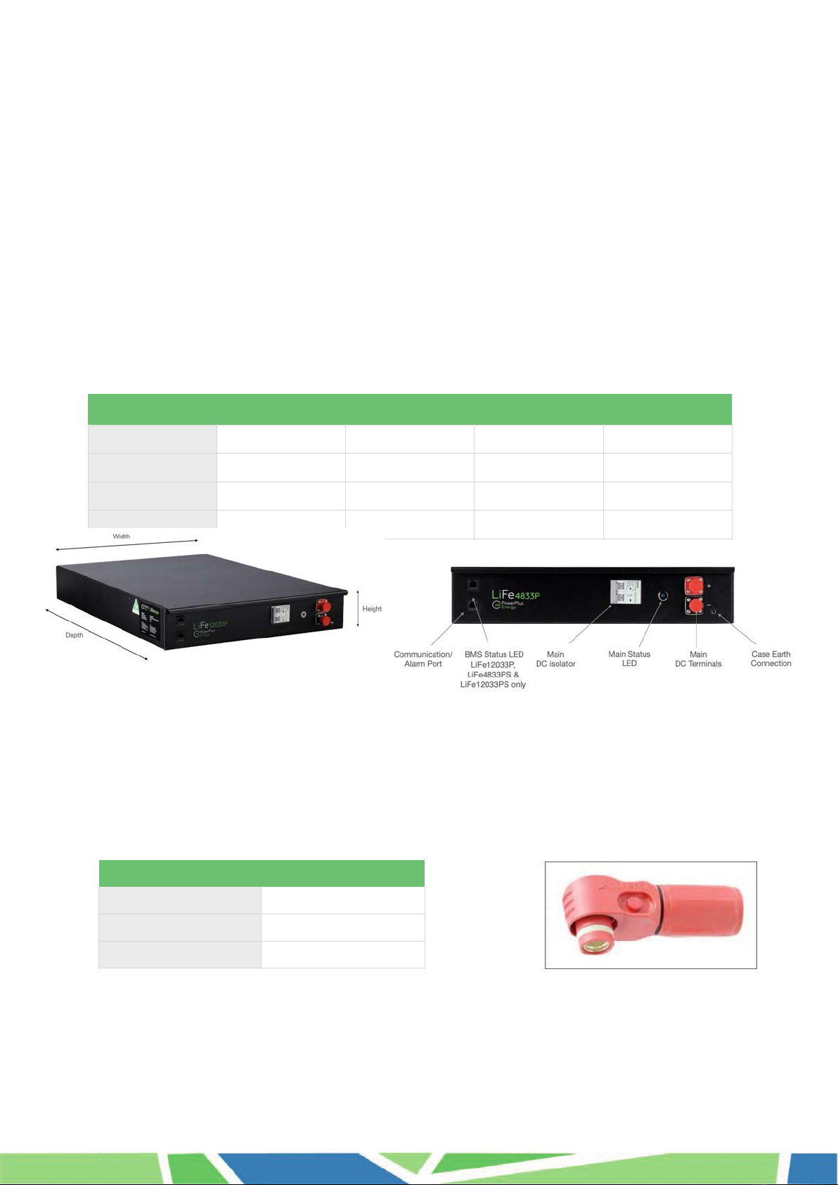
3.1. Weight and Dimensions 8
3.2. Inclusions 8
3.3. Specifications 9
3.3.1. LiFe Premium P Series 9
3.4. Charging and Discharging 10
3.4.1. Primary Charging Source 10
3.4.2. Secondary Charging Source 10
3.4.3. Calibration to 100% 10
3.4.4. Battery Charging Requirements PCE for P Series 11
3.4.5. Charging Curves P Series 12
3.4.6. Discharging Curves P Series 13
3.4.7. State of Charge Vs Discharge Voltage P Series 14
3.4.8. Over Discharged battery 14
3.4.9. Circuit Breaker Characteristic 15
4. Installation 16
4.1. Location and Environment 16
4.1.1. Extreme Humidity Climates 16
4.2. Battery Installation 17
4.2.1. Custom Cabinets 17
4.2.2. Battery Orientation Stationary Application 18
4.2.3. Battery Orientation Pre-Assembled BESS or BS Systems 18
4.2.4. Battery Orientation Motorhomes, RV’s, Trailers, Vehicles, Trucks, Buses or Similar 18
4.3. Battery Connections 19
4.4. Main DC Connections 19
4.5. Case Earthing 20
4.6. Battery Alarm and Communication Installation 21
4.6.1. Data Logging 22
4.6.2. PowerLink 22
4.6.3. PowerLink Installation 22
5. PowerPlus Energy Battery Enclosures 23
5.1. Rack Series Enclosures 23
5.1.1. Rack Series Specification 23
5.1.2. Rack Series Enclosure Installation 24
5.2. SlimLine Series Enclosures 25
5.2.1. SlimLine Series Specification 25
5.2.2. PEW3 & PEW4 Installation 26
5.3.3. PEF6W-250B Installation 27
5.3.4. PEF9W-250 Installation 28
6. Battery Operation 29
6.1. Main Status LED 29
6.2. BMS Status LED 29
6.3. Battery Power up / Shut Down Procedure 30
6.3.1. Battery Startup 30
6.3.2. Battery Shut Down 31
6.3. Full Recharge Upon First Installation 32
6.4. Calibration to 100% (Weekly recharge to 100%) 32
6.5. SoC (State of Charge) Drift 32
7. Troubleshooting 33
7.1. Over Discharged Battery Recovery 33
7.1.2. BMS Threshold Soft Shutdown 33
7.1.3. Soft Shutdown Recovery 33
7.1.3. BMS Threshold Hard Shutdown 34
7.1.4. Hard Shutdown Recovery 34
8. Maintenance 35
9. Upgrading Battery Capacity 35
10. Capacity Testing Battery 36
11. End of Life 37
12. Warranty 37
LiFe Premium P Series Installation Manual V7.0
21/10/2021 Page of3 37

LiFe Premium P Series Installation Manual V7.0
21/10/2021 Page of4 37

2. Safety
Installers and users are responsible for familiarising themselves with this manual.
The LiFe Premium P Series batteries use high grade cylindrical Lithium Ferro Phosphate (LFP) cells which
are robust and reliable in higher ambient temperatures, have a long service life and contain no heavy
metals and are mostly recyclable.
Each LiFe Premium P Series battery has an internal Battery Management System (BMS) that provides
protection against over and under voltage, over current, over temperature, short circuit and provides
reliable service life through managing cell string balancing.
Each battery has a 2 pole non polarised K Curve circuit breaker, status indicator light, volt free alarm
contact and high quality Amphenol SurLok DC connections for safe and easy installation.
Installation should carried out by a suitably qualified and experienced person who can specify the correct
cables, DC bus arrangement, external circuit protection, polarity checking and suitability of the design for
the installation according to all necessary local/international standards and requirements within this manual.
2.1. Transportation
PowerPlus Energy’s LiFe series Lithium Ferro Phosphate Batteries are classed as Dangerous Goods
(DG) Class 9 UN3480.
They are safe for road transport. The batteries are shipped in a partially discharged state with terminal
protection and the circuit breaker off.
Batteries where possible, should be shipped in the original manufacturer’s packaging, positioned
horizontally and secured to a pallet. Batteries should not be stacked more than 6 batteries tall or shipped
vertically.
LiFe Premium P Series Installation Manual V7.0
21/10/2021 Page of5 37

2.2. Basic Safety
The following precautions should be observed:
•Battery should not be exposed to temperatures above or below the temperature ratings specified within
this manual.
•Battery should not be installed in direct sunlight.
•Battery should not be exposed to strong impacts.
•Battery should not be crushed or punctured.
•Battery connectors should not touch conductive surfaces unless intended to do so.
•Battery is non-user serviceable and should not be opened for repair.
•Battery has no maintainable components and is should not be disassembled.
•Battery should not be touched if wet.
•Battery should be kept dry at all times.
•Battery should be kept away from animals and children.
•Battery pack should not be exposed to pressure, or have objects stood on top of them.
•Battery pack is intended to be a 2 person lift when installing.
2.3. Handling
•Use battery only as directed.
•The batteries are heavy and proper lifting techniques or equipment should be applied.
•Do not use the battery if it appears damaged or broken.
•Handle battery with care when installing or transporting.
•Do not use chemicals to clean the battery.
•Do not touch the DC terminals.
•Do not touch the DC Busbar.
2.4. Storage of Battery
•Battery should be stored horizontally and stacked no more than 6 batteries tall without extra support.
•Battery should be kept in a dry environment away from moisture.
•Battery should be stored away from incompatible substances.
•Battery should be stored between 0 to 45°C, however close to 25°C should be considered for long term
storage.
•After 6 months of storage the battery may need cell balancing and should be charged. Any issues with
charging after long term storage should be discussed with PowerPlus Energy.
2.5. LiFe Support
Our batteries should not be used in life support applications where failure of our LiFe batteries can
reasonably be expected to cause failure of the life support equipment or effect operation of such
equipment.
LiFe Premium P Series Installation Manual V7.0
21/10/2021 Page of6 37

2.6. Damaged Battery
A damaged battery should not be used and should be returned to PowerPlus Energy or disposed of via a
recycling facility. Leaking electrolyte can cause skin irritation and chemical burns, so contact should be
avoided.
Eye Contact: Rinse gently with running water and seek medical attention if irritation develops.
Skin Contact: Rinse gently with running water and seek medical attention if irritation develops.
Ingestion: If ingested, do not induce vomiting and contact you local poisons information centre or
doctor.
Inhalation: Evacuate area and seek professional medical attention immediately.
Refer to product SDS document for more details which is available from PowerPlus Energy’s web page or
upon request.
2.7. Fire
Should the battery pack catch on fire or start to emit smoke, (for small fire or small emissions of
smoke) use water spray, dry chemical, carbon dioxide or chemical fire extinguisher.
Evacuate the area and call emergency services.
Some toxic gases may be produced if the battery catches fire.
The battery needs to be rapidly cooled to prevent any heat or fire spreading.
Refer to product SDS document for more details which is available from PowerPlus Energy’s web page or
upon request.
2.8. Qualified Person (Installer)
This manual and task sets within regarding installation should be carried our by a suitable qualified and
skilled person.
The installer needs to be a person with adequate skills, qualifications and experience.
They should:
•Have a thorough understanding of operations, design and installation principles of battery energy storage
systems.
•Have a thorough understanding of all dangers and risks associated with installing and using electrical
devices.
•Hold all local, state and country base qualifications to carry out such work.
•Adhere to all safety and installations requirements within this manual.
LiFe Premium P Series Installation Manual V7.0
21/10/2021 Page of7 37

3. Product Information
The technical information presented here within, outlines the physical and electrical characteristics of the battery
and what environment they should be installed in.
The LiFe P Series batteries are self-managed with an internal BMS within each battery to protect it from over
voltage, under voltage, over temperature and over current.
The Battery does not require communication with the Power Control Electronics (PCEs) to operate. The LiFe P
Series can operate with PCE (Power Control Electronics) that do not require communications to operate.
If you are unsure, please consult your PowerPlus Energy expert or the PowerPlus Energy web page for advice.
3.1. Weight and Dimensions
3.2. Inclusions
Each battery comes supplied in a cardboard box that should be retained in case there is a need to return
the battery to PowerPlus Energy. All batteries except those supplied with as PowerPlus Energy cabinet will
come supplied separately with corresponding DC connectors. All other accessories are sold separately.
LiFe Premium P Series Installation Manual V7.0
21/10/2021 Page of8 37
LiFe2433P
LiFe4833P
LiFe4822P
LiFe12033P
Depth
635mm
635mm
420mm
635mm
Width
434mm
434mm
434mm
434mm
Height
88mm
88mm
88mm
88mm
Weight
41kg
41kg
30kg
41kg
DC Connector
Positive DC connection
1 x SLPPA16BSR
Negative DC Connection
1 x SLPPA16BSB
25mm to 16mm reducer
x 2

3.3. Specifications
3.3.1. LiFe Premium P Series
LiFe2433P
LiFe4833P
LiFe4822P
LiFe12033P
Nominal DC Voltage
25.6V
51.2V
128.0V
Operational Voltage Window
20V to 29.2V
40V to 58.4V
40V to 58.4V
(110V) / 123.2V to 146V
Nominal Capacity
3.3KWh (3.277) / 128Ah
3.3KWh (3.277) / 64Ah
2.2kWh (2.211) / 43Ah
3.3KWh (3.277) / 25.6Ah
Usable Capacity
3.3kWh (3.277)
3.3kWh (3.277)
2.2kWh (2.211)
2.97kWh (2.95)
Recommended Usable Capacity
2.64kWh
2.64kWh
1.76kWh
2.64kWh
Depth of Discharge
Up to 100%
Up to 90%
Recommended Depth of Discharge
80% or less
Continuous Discharge C-Rate
0.5C (C2)
1C (C1)
Continuous Discharge current
63A
63A
43A
25A
Continuous Discharge Power
1.61kW
3.22kW
2.20kW
3.20kW
Maximum Discharge
(Limited by K-Curve Circuit Breaker)
(Refer manual for circuit breaker characteristics)
63A* (1.61kW)
63A* (3.22kW)
63A* (3.22kW)
25A* (3.20kW)
Maximum Charge Current
63A
63A
63A
25A
Warrantable Charge Current
63A
32A
21.5A
12.8A
Warrantable Charge Power
1.61kW
1.63kW
1.10kW
1.63kW
Prospective Fault Current (1ms)
250A
110A
Circuit Breaker (k Curve)
2-Pole 63A 360VDC
2-Pole 25A 360VDC
Lithium Composition
Lithium Ferro Phosphate (LiFeP04 or LFP)
Operating Temperature Range
Charge: 0° to 55°C / Discharge -20° to 60°C
Ideal Operating Temperature Range
0 to 45°C
Operating Humidity
85% Non Condensating
BMS Over-Volt
Cell Level Protection
3.9V/Cell
3.7V/Cell Average
BMS Under-Volt
Cell Level Protection
2.0V/Cell
Soft Shut down 3.08V/Cell
Hard Shut down 2.75V/Cell
BMS Over-Temp Cut Off
65°C
55°C Charge
60°C Discharge
BMS Max Trip Current
200A
100A
Self Discharge
14% Per Annum
Altitude
< 2000m (seek manufacturers advice above 2000m)
Battery Mounting Options
Standard 19” Rack Mount / Horizontal / Vertical
Terminal Connections
Amphenol Surlok 100A Non Keyed
IP Rating
IP40
Efficiency
>96%
Cooling
Natural convection
Parallel Connection
Unlimited - Refer Manufacturer
Serial Connection
Not Permitted
Alarm Output
Normally closed, Volt free, 1A maximum
Communications
Alarm Output
Battery Performance data via
PowerLink Data device +Alarm
output
Module Weight
41kg
30kg
41kg
Battery Dimensions
635mm D x 434mm W x 88mm H
420mm D x 434mm W x 88mm
H
635mm D x 434mm W x 88mm H
Arc Flash Incident Energy
IEm in Cal/cm2 (45cm)
0.25
0.36
0.36
0.54
Arc Flash Incident Energy
AFB in cm
20.45
24.45
24.45
30.19
Certifications
Pending IEC: 62619:2017,
UN38.3, EMC
Pending IEC: 62619:2017,
UN38.3, EMC
Pending
Pending IEC: 62619:2017,
UN38.3, EMC
Terminal Connections
Amphenol Surlok 100A Non Keyed
Note:
This specification is subject to change at anytime without notice
Warranty
10 Years (Conditions apply)
LiFe Premium P Series Installation Manual V7.0
21/10/2021 Page of9 37

3.4. Charging and Discharging
The battery should be charged and discharged within the operating temperature windows as outlined within
the specifications and as indicated in the Charge Discharge table below “Connected PCE Programming
Requirements”. All currents are maximum for each battery, and should be taken into consideration when
multiple devices are charging the battery.
3.4.1. Primary Charging Source
A Primary Charging Source should be identified in the system and programmed to charge the batteries as
outlined in the table below. A primary charging source, is the charging device that will be used to charge
the battery for 75% of the time (charge energy) or higher.
3.4.2. Secondary Charging Source
A Secondary Charging Source can also be used, the preference is to also have these devices programmed
to the charging settings in the table “Connected PCE Programming Requirements”. However if this is not
possible, they can be used as long at the output voltage does not exceed the upper voltage of the
Operational Voltage Window of the battery, does not exceed the Max Charge Current, and does not
account for more than 25% of the charging (energy) of the battery.
Example
Primary Charging Source = Solar PV will be used to perform 75% of charging and will be programmed as
per below table.
Secondary Charging Source = Wind Turbine will be used to supply approximately 25% of the charging,
however can not have the voltage adjusted as per the specific charging voltages as specified in the table
“Connected PCE Programming Requirements”, and will not exceed the Operational Voltage Window or Max
Charge Current/Power of the battery.
3.4.3. Calibration to 100%
Calibration to 100% every 7 days (minimum) is required to perform a cell balance maintenance
charge. Cell balancing allows the BMS to equalise the battery cells to limit battery capacity slip and
ensures battery will accept the charge voltage correctly.
Calibration to 100% is achieved by:
!
Charge batteries at specified “Continuous Charge Voltage” and no greater than the specified Maximum
Charge Current.
!
Battery!is considered full after battery is absorbing less than 1% of maximum charge current after being
held at specified charge voltage for 30minutes minimum.
If PowerPlus Energy has released Custom Charge Settings for your connected PCE,!then these instructions
can be followed instead.
LiFe Premium P Series Installation Manual V7.0
21/10/2021 Page of10 37

3.4.4. Battery Charging Requirements PCE for P Series
LiFe Premium P Series Installation Manual V7.0
21/10/2021 Page of11 37
Connected PCE Programming Requirements
LiFe2433P
LiFe4833P
LiFe4822P
LiFe12033P
Shutdown DC Voltage @0.5C
24.0V
48.0V
123.75V
Shutdown Voltage Recommended
25.1V
50.2V
125.5V
Recovery / Restart Voltage
26V
52V
130V
Continuous Charge Voltage
28.8V
57.6V
142V
Continuous Charge Transition
Battery!is considered full after battery is absorbing less than 1% of maximum charge current after being held at specified charge
voltage for 30minutes minimum.
Float Voltage Cyclic
(Short Term Float)
(Example Solar Application)
28.8V
57.6V
142V
Float Voltage Standby
(Long Term Float)
(Example UPS Application)
27.2V to 28V
54.4V to 56V
140V
Charge Current
63A
32A
21.5A
12.8A
Peukert Exponent
1.02
Shutdown SoC (Recommended)
20%
Calibration to 100%
Every 7 days or more frequent where possible.
(Ensures cell balancing is performed & keeps external SoC counter more accurate)
Note
These charging requirements are subject to change at anytime without notice

3.4.5. Charging Curves P Series
LiFe Premium P Series Installation Manual V7.0
21/10/2021 Page of12 37
28.8
57.6
142
141
Voltage/Current Curve for charging LiFe2433P
Voltage/Current Curve for charging LiFe4833P
Voltage/Current Curve for charging LiFe12033P

3.4.6. Discharging Curves P Series
LiFe Premium P Series Installation Manual V7.0
21/10/2021 Page of13 37

3.4.7. State of Charge Vs Discharge Voltage P Series
The below table can be used a guide for referencing voltage against energy in the battery.
The below figures are taken at 25°C and with a 0.5C load applied.
3.4.8. Over Discharged battery
In the event that the batteries low voltage protection circuit has operated to protect the battery form
excessive discharge, it is important that the battery is charge to 100% within 7 days. Leaving the battery in
a discharged can cause irreversible damage to the battery or battery capacity.
LiFe Premium P Series Installation Manual V7.0
21/10/2021 Page of14 37

3.4.9. Circuit Breaker Characteristic
The integrated non-polarised DC circuit breaker is dual pole and a K curve type. The table below outlines
the trip times based on current.
LiFe Premium P Series Installation Manual V7.0
21/10/2021 Page of15 37
Multiple of circuit breaker rated current
Time in Seconds

4. Installation
Installation should be carefully considered and all aspects of the specifications should be
understood to determine a suitable location and way of installing the battery.
4.1. Location and Environment
The location of the battery should be in accordance with the IP rating and operating temperature range
specified in the specification section of this manual.
The location of the batteries should meet the below conditions:
•The Battery should not be installed where direct contact of salt air may be possible. If unavoidable,
appropriate air filtration must used to prevent salt air contacting the battery, and the battery installation
should be indoors or an IP66 or greater enclosure.
•The floor is level and free from obstructions.
•There are no explosive or flammable materials nearby.
•The Ideal Temperature around the battery is between 0 and 45°C.
•Operation of charge and discharge outside of the Ideal Temperature should be limited to 0.2C and still
remain within the Operating Temperature Range as specified in the specification.
•The temperature and humidity should remain as constant as possible.
•The area is of a clean environment with minimal dust.
•The area or enclosure is vermin proof to suit your environmental locations.
•The batteries and battery cabinets/housings are not exposed to direct sunlight.
The LiFe Premium P Series battery is designed to be installed in a 19 inch data rack assembly or an
electrical enclosure of your choice. If the battery is to be installed outdoors a suitable IP54 or great
enclosure should be used.
4.1.1. Extreme Humidity Climates
When our batteries are being installed in climates of extreme humidity, extra precaution should be taken.
•A humidity control agent (i.e. chemical which absorbs humidity) may be required inside the enclosure,
with controlled airflow to expel moist air.
•And or, the battery system to be installed in a moisture and climate controlled room (example, reverse
cycle air-conditioner cooled).
•The temperature of the cabinet should be held at a temperature above dew point at all times.
LiFe Premium P Series Installation Manual V7.0
21/10/2021 Page of16 37

4.2. Battery Installation
PowerPlus Energy highly recommends our range of Rack or SlimLine Series indoor and outdoor cabinets.
Full Specification details are available on the PowerPlus Energy web page, however specific installations
details are further along in this manual.
4.2.1. Custom Cabinets
The battery has been designed to fit into a standard 800mm deep 19inch rack enclosure.
If you are building your own enclosure, ensure the below is considered in your design.
•If the battery is installed in to enclosures without rails, please ensure that they are securely seated to
prevent accidental damage or tampering.
•If a custom enclosure or mounting method is used please ensure the batteries are not stacked more than
6 high unless battery support rails are used to distribute weight.
•Please ensure there is adequate air flow around the battery stack within the cabinet. 15mm minimum
around 4 side of the stack is required as minimum.
•Please ensure the selected IP rating is correct as per your location selection.
•All interconnecting battery cables for parallel connection shall be the same length and cable size.
•A busbar is recommended for connection of all parallel battery connections.
•An appropriate way of connecting the cabinet to the PCE should be considered.
•Please follow PCE instructions for fuse, cable and connection requirements. These will vary depending on
brand and product selected.
LiFe Premium P Series Installation Manual V7.0
21/10/2021 Page of17 37

4.2.2. Battery Orientation Stationary Application
The LiFe batteries can be mounted in 4 orientations, excluding on its face or upside down.
4.2.3. Battery Orientation Pre-Assembled BESS or BS Systems
•Batteries should be shipped horizontally and secured in place to limit movement.
•If batteries are to be subject to prolonged vibrations during transportations, they should be removed and
shipped in original manufacturers packaging or a sufficient non-flammable shock mount system (like high
density foam or similar) should be installed within the BESS/BS under each battery.
4.2.4. Battery Orientation Motorhomes, RV’s, Trailers, Vehicles, Trucks,
Buses or Similar
•Batteries should be shipped horizontally and secured in place to limit movement.
•Batteries should be positioned in a non-flammable section and be easily accessible and removable form
the outside of the vehicle.
•Sufficient non-flammable shock mount system (like high density foam or similar) should be installed within
the BESS/BS under each battery.
LiFe Premium P Series Installation Manual V7.0
21/10/2021 Page of18 37

4.3. Battery Connections
Each battery has a positive and negative Amphenol SurLok (non keyed) male connector for easy snap on
connection. A range of cables and mating connectors are available from any PowerPlus Energy place of
purchase.
If multiple batteries are being used in parallel, the battery cables shall all be of the same length to retain
equal impedance of each battery and cable set.
4.4. Main DC Connections
The battery comes fitted with Amphenol Surlok connectors (non keyed) male connectors. The table below
outlines the battery connections and the mating cable connectors required. Each battery when ordered
separately (without a cabinet) will come supplied with mating connectors.
Each Amphenol SurLok connector supplied by PowerPlus Energy can adequately seat 25mm single
insulated or 16mm double insulated cable. A 16mm reducing sleeve is provided. Crimping of SurLok to the
stripped end of the cable is performed using a standard 25mm hex crimp tool.
Before connecting the DC cable to the battery you will need to remove the safety insulating cap on the
battery DC connectors and dispose of appropriately.
Battery
Cable
Positive connection
SLPRATPSR
SLPPA16BSR
Negative Connection
SLPRATPSB
SLPPA16BSB
LiFe Premium P Series Installation Manual V7.0
21/10/2021 Page of19 37

4.5. Case Earthing
The LiFe battery case is designed to be electrically floating and isolated from all internal battery
connections and in most installations will not require earthing. However should your application require the
case to be grounded a 5mm M6 bolt should be used and is supplied with the battery.
LiFe Premium P Series Installation Manual V7.0
21/10/2021 Page of20 37
Other manuals for LiFe Premium P Series
2
Table of contents
Other PowerPlus Energy Camera Accessories manuals

PowerPlus Energy
PowerPlus Energy Eco P Series User manual

PowerPlus Energy
PowerPlus Energy Eco P Series User manual

PowerPlus Energy
PowerPlus Energy LiFe Premium 2RU19 User manual

PowerPlus Energy
PowerPlus Energy LiFe Premium P Series User manual

PowerPlus Energy
PowerPlus Energy Eco P Series User manual

PowerPlus Energy
PowerPlus Energy LiFe4838P User manual

PowerPlus Energy
PowerPlus Energy LiFe Premium Series User manual

PowerPlus Energy
PowerPlus Energy LiFe Premium P Series User manual