PowerPlus Energy Pty Ltd 12/05/2023 | V3.6 page 7 of 20
3.4 CHARGING AND DISCHARGING
The battery should be charged and discharged within
the operating temperature windows as outlined within
thespecicationsandasindicatedintheCharge
Discharge table below “Connected PCE Programming
Requirements”. All currents are maximum for each
battery, and should be taken into consideration when
multiple devices are charging the battery.
3.4.1. PRIMARY CHARGING SOURCE
APrimaryChargingSourceshouldbeidentiedinthe
system and programmed to charge the batteries as
outlined in the table below. A primary charging source,
is the charging device that will be used to charge the
batteryfor75%ofthetime(chargeenergy)orhigher.
3.4.2. SECONDARY CHARGING SOURCE
A Secondary Charging Source can also be used, the
preference is to also have these devices programmed
to the charging settings in the table “Connected PCE
Programming Requirements”. However if this is not
possible, they can be used as long at the output voltage
does not exceed the upper voltage of the Operational
Voltage Window of the battery, does not exceed the Max
Charge Current, and does not account for more than
25%ofthecharging(energy)ofthebattery.
3.4.4. BATTERY CHARGING REQUIREMENTS PCE FOR P SERIES
Example
Primary Charging Source = Solar PV will be used to
perform 75% of charging and will be programmed as
per below table.
Secondary Charging Source = Wind Turbine will be
used to supply approximately 25% of the charging,
however can not have the voltage adjusted as per the
specicchargingvoltagesasspeciedinthetable
“Connected PCE Programming Requirements”, and
will not exceed the Operational Voltage Window or Max
Charge Current/Power of the battery.
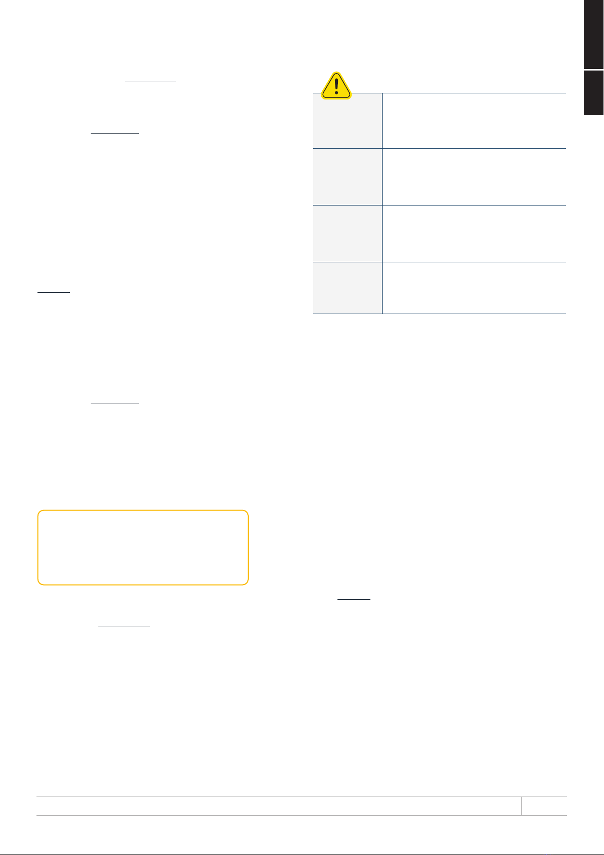
3.4.3. CALIBRATION TO 100%
Calibrationto100%every7days(minimum)isrequired
to perform a cell balance maintenance charge. Cell
balancing allows the BMS to equalise the battery cells
to limit battery capacity slip and ensures battery will
accept the charge voltage correctly.
Calibration to 100% is achieved by:
Chargebatteriesatspecied“ContinuousCharge
Voltage”andnogreaterthanthespeciedMaximum
Charge Current.
Battery is considered full after battery is absorbing less
than 1% of maximum charge current after being held at
speciedchargevoltagefor30minutesminimum.
IfPowerPlusEnergyhasreleasedCustomCharge
Settings for your connected PCE, then these
instructions can be followed instead.
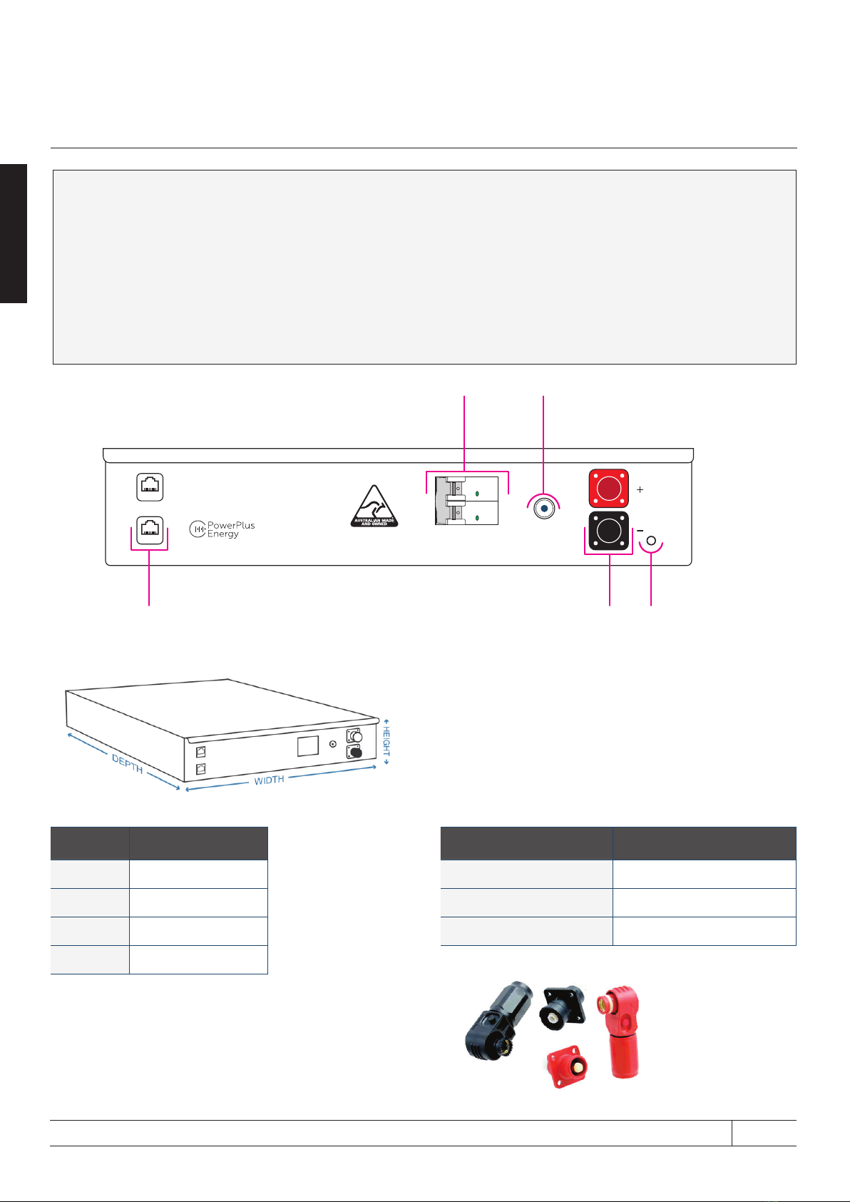
3. Product Information
Connected PCE Programming Requirements
Shutdown DC Voltage @0.5C 48.0V
Shutdown Voltage Recommended 50.2V
Recovery / Restart Voltage 52V
Continuous Charge Voltage 57.6V
Continuous Charge Transition Battery is considered full after battery is absorbing less than 1% of maximum
chargecurrentafterbeingheldatspeciedchargevoltagefor30minutesminimum.
Float Voltage Cyclic (Short Term Float) (Example
Solar Application) 57.6V
Float Voltage Standby (Long Term Float) (Example
UPS Application) 54.4V to 56V
Charge Current 39A
Peukert Exponent 1.02
Shutdown SoC Recommended 20%
Calibration to 100% Every 7 days or more frequent where possible.
(Ensurescellbalancingisperformed&keepsexternalSoCcountermoreaccurate)