PowerTherm MAX45 User manual

Read me first
Thank you for using welder ! For the important safety of your body,
please read this manual book and understand its contents before
operation.
Thank you for your cooperation!
PLASMA CUTTER
MAX 45/125
USER`S MANUAL

- 1 -
Content
1. Use and Characteristic:.....................................................................................2
2. Safty Precaution ..................................................................................................2
3. Precautions of electromagnetic compatibility .....................................................5
4. Main technical information .................................................................................7
5. Installation:.......................................................................................................8
6. Model establishment and illustration:..............................................................9
7. Brief description of the principle:...................................................................10
8. Operation and instruction:..............................................................................11
9. Welding machine precautions and maintenance:............................................24

- 2 -
Use and Characteristic
CUT series of inverter air plasma cutting machine which could be used for the cutting
of various metal materials, such as stainless steel, alloy steel, carbon steel, cast iron, copper and
aluminum. As this series of arc welding power source possesses ideal external characteristics and
excellent dynamic characteristics, and it's control function is perfect, it has the following
features:
IGBT high-frequency alternate, efficient, ,light in weight;
Control and adjusting function is good, one welder serves several purposes, easy to use;
It’s easy to start arc, stability of arc and high welding quality;
Rapid cutting speed, smooth cutting surface;
Safty Precaution
Generally Safety Precaution
Ensure to follow precautions specified in this manual, or else, an accident may happen.
The design and construction of input power supply, selection of installation site and use
of high pressure gas shall be performed according to the relevant standards and rules.
Irrelevant personnel are not allowed to enter the welding workplace. Only the qualified
personnel can install, overhaul, maintain and operate the welding machine.
Qualified staff is needed for installation, maintenance and use.
Make sure the welding machine is not used for other purposes except welding (such as
charging, heating and pipeline unfreezing, etc).
If the ground is uneven, please avoid dumping welding machine.
Avoid electrical shock or burn
Touching electric parts is forbidden.
Ensure to invite professional electrician to ground the welding machine with copper
conductor with specific cross section.

- 3 -
Ensure to invite professional electrician to connect power source in welding machine
with copper conductor with specific cross section. The insulating sheath cannot be
damaged.
Ensure to insulate the body and base metal when working in the wet and restricted area.
Please use safety net when working at heights.
Please close the input power when not in use.
Avoid welding fume and gas damaging human body
Ensure to use specified exhaust equipment to avoid gas poisoning and suffocation.
The protective gas will be deposited around the container bottom to cause suffocation.
Pay attention to the ventilation.
Avoid welding arc, splash and welding slag damaging human body
Ensure to wear protective glasses with enough overshadow. The arc will result in ocular
inflammation and the welding splash and slag will burn eyes.
Ensure to use protective supplies for welding, such as leather protective gloves, caftan,
cap, welding spats and apron to avoid welding arc light, welding splash and slag
burning skin.
Avoid fire, explosion and fracture and other accidents
The welding place cannot have the combustibles because splash and hot weld joint will
result in fire.
The cables and base metal must be connected firmly, or else, it may be heat to result in
fire.
Must not weld in the combustible gas or container with the combustibles, or else, it may
result in explosion.
Ensure to prepare fire extinguisher just in case.

- 4 -
To prevent the rotating moving parts wounding
Must not make fingers, hair and clothes close to the cooling fan and wire feed roll and
other rotating parts.
When feeding wire, must not make the welding gun end close to eyes, face and body to
avoid wire damaging person.
Avoid falling gas cylinder and breaking gas regulator
The gas cylinder shall be fixed reliably, or else it may dump to result in human injury.
Must not put gas cylinder in a place with high temperature or sunshine.
When opening gas cylinder valve, must not make face close to the gas outlet, or else
high-pressure gas may damage person.
Ensure to use gas regulator provided by the company and follow the use regulations.
Prevent the movement of welding
Must not stand under the welding machine and motion direction when moving welding
machine with fork lift truck or crane, or else, the welding machine may fall to cause
injury.
The rope sling shall bear enough pull force and cannot be broken when suspending. The
angle between rope sling and hook shall be no more than 30°.

- 5 -
Precautions of electromagnetic compatibility
1. Overview
Welding brings electromagnetic interference.
Minimize the interference emission of arc welding equipment with proper installation way
and correct application method.
The products described in the manual belong to Class A equipment (all occasions except
residential area powered by public electrical power system).
Warning: Class A equipment is not applicable to residential area powered by public
electrical power system. It is difficult to guarantee electromagnetic compatibility because of
conduction and radiated interference.
2. Advice of environment assessment
Before installing the arc welding equipment, the user shall evaluate the potential
electromagnetic disturbance of the surrounding. The considerations are as follows:
Check surrounding of arc welding equipment for other power cables, control cables, signals
and telephone wire.
Check for broadcasting and television launching and receiving equipment;
Check for computer and other controllers;
Check for high security level equipment, such as industrial protective equipment;
Consider the health of surrounding staffs, such as staffs with hearing aid and cardiac
pacemaker;
Check for calibrating or detection equipment;
Pay attention to immunity to interference of other equipment. The user shall make sure that
the surround equipment can be compatible. The additional protective measures may be
required;
Welding or other activity time.
The environmental range is decided based on the building structure and possible activities.
This range may exceed the boundary of building.
3. Method of reducing radiation emission
Public power supply system

- 6 -
The arc welding equipment shall be connected into public power supply system with the
method recommended by the manufacturer. In case of interference, please take addition
preventive measures, such as connecting filter with public power supply system. Ensure to
consider power able shielding for fixed arc welding equipment. The power cables can be
shielded with the metal pipe or other equivalent methods. Ensure to keep electrical continuity for
shielding.
Maintenance of arc welding equipment
Ensure to perform routine maintenance for arc welding equipment according to the method
recommended by the manufacturer. When welding equipment runs, all equipment inlets,
auxiliary doors and panels shall be closed and tightened appropriately. The arc welding
equipment cannot be changed in any form, unless the relevant change and adjustment are
allowed in the manual. The spark gap of arc initiation device and arc stabilizing device shall be
adjusted and serviced according to the suggestion of manufacturer.
Welding cable
The welding cable shall be short as much as possible and close to each other. Moreover,
welding cable shall be next to or close to ground cable.
Equipotential lap
Pay attention to lapping of metal objects in the surrounding. The lapping of metal objects
and workpiece will increase job hazard. When the operator touches these metal objects and
electrode, he may suffer from electrical shock. The operator shall be insulated from these metal
objects.
Workpiece earthing
The workpiece may be not provided with earthing because of electrical safety or workpiece
position, such as hull or building steel frame. When earthing is available for workpiece, radiation
emission may be reduced. But it is not always the case. Therefore, we must prevent the increased
risk of electric shock of users caused by the workpiece earthing or the damage of other electric
equipment. When necessary, some workpiece should be directly earthed, but directly grounding
is not allowed in some countries, user can achieve this effect only by selecting the appropriate
capacitor according to the regulations of the host countries.

- 7 -
Shielding
The shielding of surrounding equipment and other cables can reduce the electromagnetic
interference. The whole welding area can be shielded for special applications.
Main technical information
1. Main technical parameter
MAX45 MAX125
Power voltage (V) AC220V±15%AC380V±15%
Frequency (Hz) 50/60
Rated input current(A) 25 29
Rated input capacity(KVA) 5.5 19
No-load voltage (V) 243 325
Output current adjustment(A) 20-40 30-120
Rated output voltage (V) 96 128
Cyclic duration factor (%) 60 60
No-load loss (W) 100 100
Arc-striking way
Arc-striking by
contacting
Arc-striking withuot
contacting
Efficiency(%) 70 80
Power factor 0.93 0.93
Insulation grade F F
Protection grade IP21 IP21
Weight (kg) 6.9 38
Size (mm) 375*155*300 690*335*575
model
parameter

- 8 -
Installation
1. Environment
Install in a dry environment with humidity less than 90% at 20℃ and 50% at 40℃.
The temperature should be in the range of -10℃-40℃ when welding, and -20℃-55℃ for
storage and transportation.
Shelter the machine from direct sunshine and rain. Avoid raindrops.
Avoid using it in an environment with strong air flow when TIG welding.
The inclination of the welding power is less than 100 the altitude no more than 1000m.
Avoid using it in a dusty, acid or other corrosive environment.
The machine should be placed more than 20cm from the wall, and more than 10cm from
other welding machines.
2. Requirement of the input power source
Waveform: standard pure sine wave
Fluctuation range: 220V or 380V ±15%
Frequency: 50Hz/60Hz
3. Input power
Model MAX45 MAX125
Input power AC220V±15% AC380V±15%
Min. power of power grid 7 22
Input
protection
Fuse 40 40
Circuit breaker 63 63
Cable
input 2.5mm24mm2
output 10mm216mm2
ground 2.5mm24mm2
Enlarge the input , output and grounding cable according to the cable length.
Remark: the specifications of fuse and circuit breaker in the table above are only for reference.

- 9 -
Control Circuit
High
frequency
High frequency
transformer
Rectifier
Rectifier filter
4. Installation of the machine
The power supply of this series of products should be single phase AC 220V 50/60Hz. Use
a distribution cabinet with an automatic air switch. Ensure safe grounding.
4.1 CUT welding:
Connect the earth cable to the positive pole, cut torch to the negative pole.
Connect the hose to the machine and gas bottle.
Turn off the machine.
Connect the input cable to the distribution cabinet, switch on.
Model establishment and illustration
CUT series welding machine model establishment and description as shown in figure 1:
CUT —×××
(table 1) CUT series welding machine model establishment and description.
Brief description of the principle
The schematic diagram of the MIG series welding machine is show figure 2:
(table 2)Welding machine schematic
Model
Air Plasma cutter

- 10
The welding machine adopts IGBT high frequency inverter technology, power frequency
220V or 380V power input,direct rectification and then sent to the inverter composed of IGBT
and other components to become high frequency alternating current, high frequency alternating
current obtained after inverter is passed through high frequency transformer after the
step-down,high frequency rectifier rectifies and filters, the output is suitable for the DC current
of the welding. Through this process, the dynamic response of the welder is improved, the
volume and weight of the transformer and the reactor are reduced, and the efficiency of the
whole machine is improved.
The design of the control circuit enables the welder to always achieve good welding
process performance when external conditions change(such as grid voltage fluctuations and
different output cable lengths).It is easy to arc,the are is stable,the weld is well formed,and the
welding current can be continuously adjusted.
CUT series welding machine output characteristics such as shown in figure 3:
90-
20-
0
U
(
V
)
U= 20+0.04I
I(A)
Imin Imax
(3A)CUT welding output characteristics
CUT welding output characteristics:Drooping characteristics.
150
80
UO=80+0.4I

- 11
Operation and instruction
1.Function
1.1 Welding machine front panel
As shown in table4, control panel is used for selecting functions and setting data of welding
machine. Control panel including digital display、adjusting knobs、selection keys and LED
indicator lights.
MAX45 (table 4)
1.1.1 MAX45 Functions selection and data setting.
①Displayer:
Display the current value;
②CURRENT:
Adjust welding current;
③O.C indicator light:
Send signals of machine over current;
Over current: there may be some components broken. Be causious restart the machine after
checking.If misjude, please just restart the machine.

- 12
④Over heat indicator light:
Over heat: machine is protected from over temperature ,
leave the machine unloaded ,after cooling it can work as usual;
1.1.2 MAX125 Functions selection and data setting.
①Displayer:
Display the current value;
②CURRENT:
Adjust welding current;
③O.C indicator light:
Send signals of machine over current;
Over current: there may be some components broken. Be causious restart the machine after
checking.If misjude, please just restart the machine.
④Work indicator light:
When there is ouput , the work indicator light is on,
otherwise it is not.

- 13
⑤2T/4T change-over switch :
Under 2T operation, the machine starts working after
pressing the switch of torch, the machine stops welding when releasing the switch.
Under 4T operation, press the switch for the first time, it gives machine start-arc
current, release the switch, current begins climbing to the normal welding current. Press the
switch again after the welding is finished, release the switch, machine stops working.
⑥Normal cutting / Reticular cutting change-over switch:
Normal cutting: pilot arc keeps 5seconds and then
break automatically; applied to flat ad seamless plate cutting
Reticular cutting: pilot arc is always on; applied to plate cutting witch big gap and gap
density, such as reticular material
⑦Gas testing/ Work change-over switch:
Gas testing: check the gas loop works well or not.
Work:machine is in working condition;
⑧Air pressure regulator:
Pressure meter and pressure regulator.

- 14
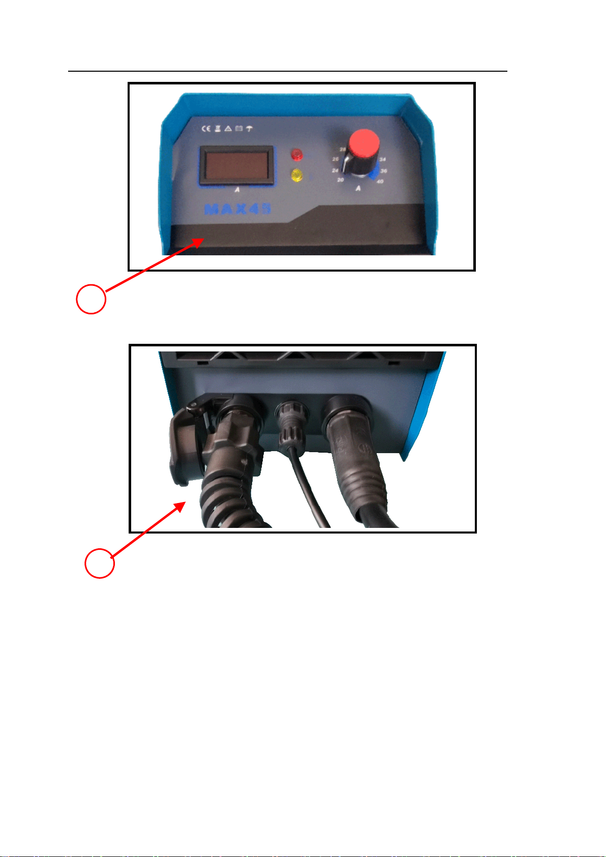
1.1.3 Welding output interface
From left:
①Cathod output gas-electric connector: connect cut torch under mode;
②Torch switch inferface:connect cut torch swith;
③Anode output inferface:connect earth clamp under mode;
(MAX45)
From left:
①Cathod output gas-electric connector: connect cut torch under mode;
②Torch switch inferface: connect cut torch swith;
③Pilot arc:pliot arc cable of the cutting torch;
④Anode output inferface: connect earth clamp under mode;
(MAX125)

- 15
2.Installation instruction:
Note:Please strictly follow below steps to install and debug!
Before electrical connect operation the user has to turn off the power switch of the
distribution panel!
This equipment protection level is IP21,avoid using in rain!
Connect the welding input power wire to the corresponding voltage level and ≥60A circuit
breaker (connect the power wire ≥4²);
The input power wire should be in good contact with the correspond power terminal or
switch ,to prevent oxidation
Use a multimeter to measure whether the input voltage is in the fluctuation range;
Connect the yellow-green wire on the power cable and the grounding screw on the rear
panel to ≥4² wire and ground well.;
If the welder is placed on an inclined plane, the welder should be secured so that it does not
slip;
Each welder is equipped with an insulated handle, which can be lifted by hand when moving
the welder
- 16
2.1 CUT welding
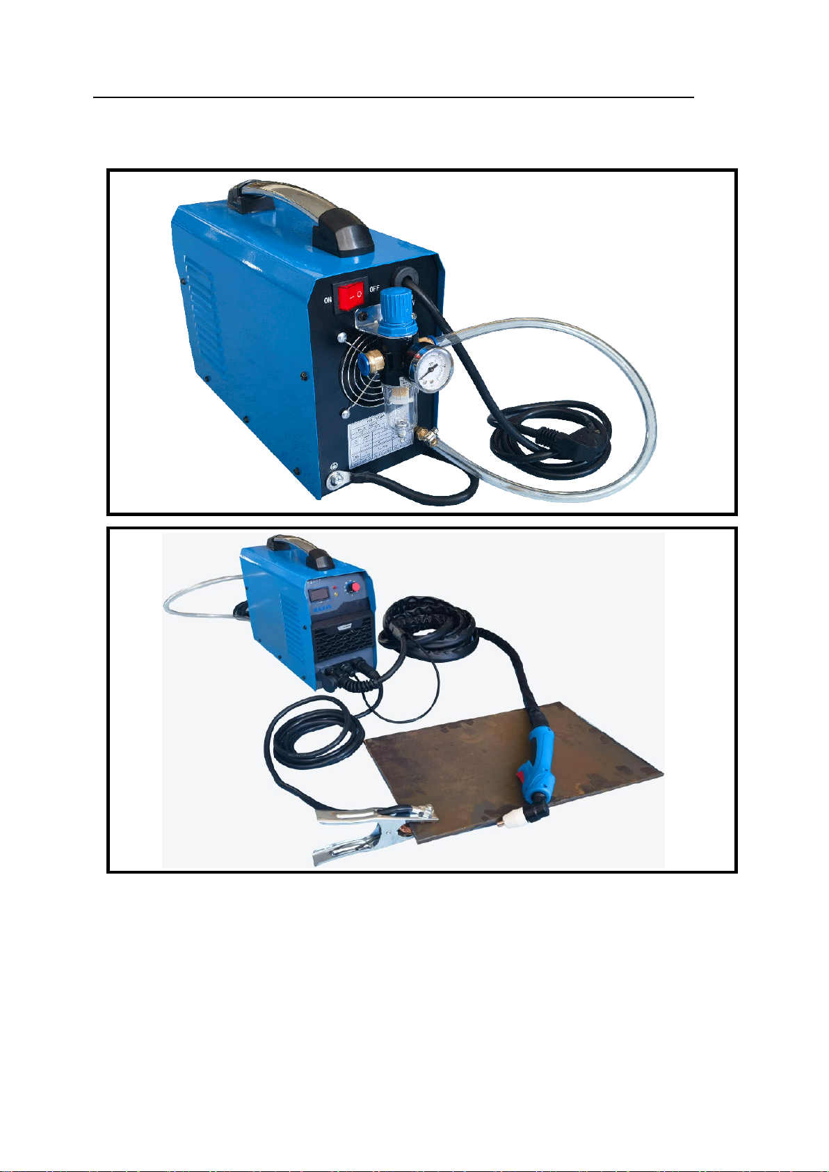
2.1.1 MAX-45
- 17
Adjust electric current
●●●●●●●●●●●●●●●●●●●●●●●●●
Connect cutter torch, torch switch, workpiece clamp.
1
2
- 18
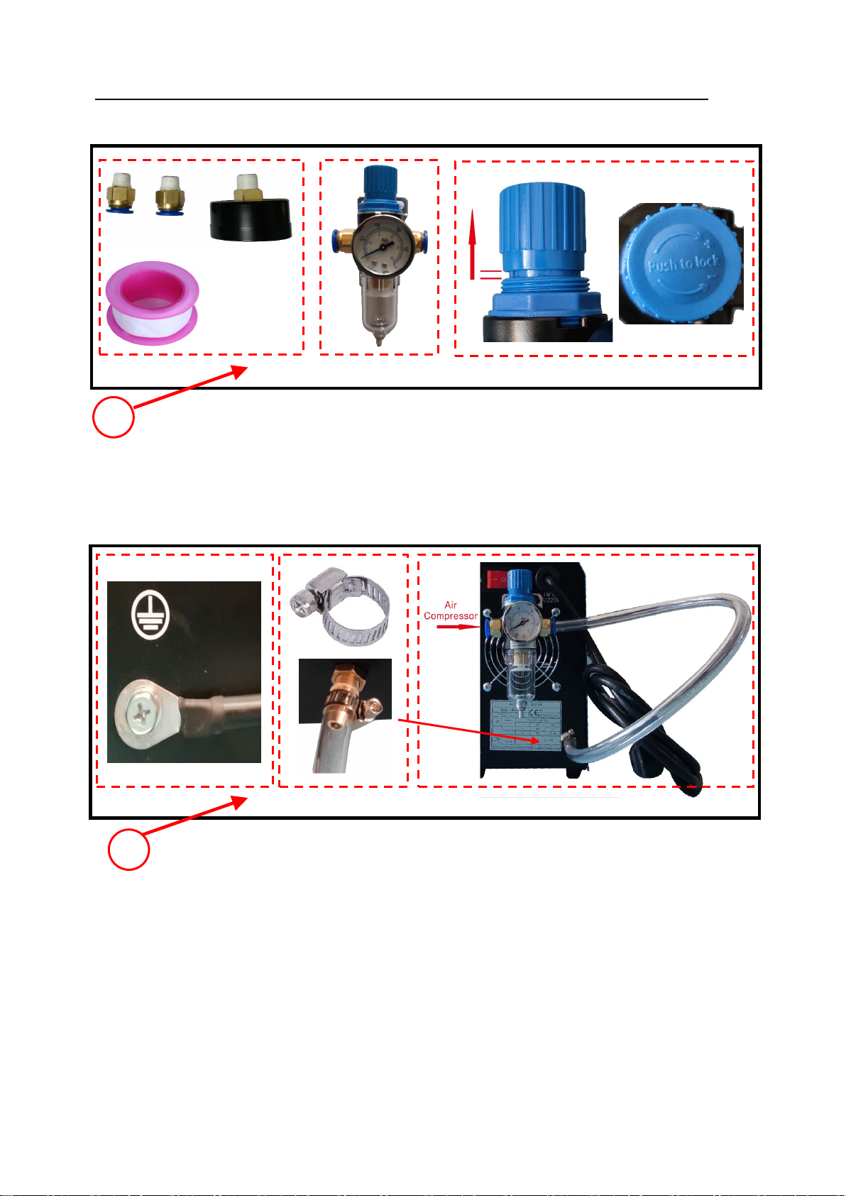
●●●●●●●●●●●●●●●●●●●●●●●●●
Using Teflon tape to wrap the pressure reducing value components, and install into the
recducing pressure reducing;Open the lid,Rotate through the direction of “+”until adjust the
pressure to around 0.4Mpa,Install the lid back.。
●●●●●●●●●●●●●●●●●●●●●●●●●●
Intall ground wire(≥2.5mm2);fix pressure reducing value ,connect air compressor,
Using hose clamp to tighten hose(8*12mm)。
3
4

- 19
●●●●●●●●●●●●●●●●●●●●●●●●●●
Turn on the air compressor, set up cutting electric current, tilt estimated 0-15degree
angle,Turn on the torch switch when the nozzle connect the workpiece,move slowly. Turn off
the torch switch when finish.
5
This manual suits for next models
1
Table of contents
Popular Welding System manuals by other brands

djm direct
djm direct DJMMIG130 manual

Lincoln Electric
Lincoln Electric LTW1 manual

ESAB
ESAB Aristotig 255 LTN 255 instruction manual

Lincoln Electric
Lincoln Electric Magnum 300 Operator's manual

Ritmo
Ritmo ELEKTRA LIGHT Operation and Maintenance Handbook

Chicago Electric
Chicago Electric 97994 Set up and operating instructions


