Powr-Flite PF1200RT Installation and operation manual

OPERATOR’S MANUAL & PARTS LIST
WARNING: OPERATOR MUST READ AND UNDERSTAND THIS MANUAL
COMPLETELY BEFORE OPERATING THIS EQUIPMENT.
©Tacony, Inc., All rights reserved
Save These Instructions
1200 P.S.I. Multi-Surface Cleaner
PF1200RT
PF1200RT-MAN 12/2015

2
NOTES
Model Number: __________________________________________________________________
Serial Number:___________________________________________________________________
Date of Purchase: ________________________________________________________________
Retain this manual as a permanent record of your purchase.

3
IntroductIon
Check the carton for shipping damage. Carefully unpack and
inspect your new Powr-Flite equipment for shipping damage.
Each unit is tested and thoroughly inspected prior to shipping.
If damage is discovered, immediately notify the transportation
company that delivered your machine and request an
inspection. As a manufacturer, we are unable to act upon any
claim for concealed damage; you must originate the claim.
Be sure to keep the carton, packing inserts, packing lists, and
carrier’s receipt until the inspector has verified your claim.
MANUAL
This manual has important information for the use and safe operation of the multisurface cleaner.
Read this manual carefully before starting the machine. Keep the manual available at all times
and instruct all operators to read this manual.
Introduction ...................................................3
Safety Instructions ........................................4
Grounding Instructions.................................5
General Diagram............................................6
Operating Instructions..................................8
Maintenance Guide........................................9
Machine Specications...............................10
Troubleshooting .......................................... 11
Schematic and Parts List............................12
PROTECT THE ENVIRONMENT
Please dispose of packaging materials in an
environmentally safe way according to local
waste disposal regulations.
Always remember to recycle
Powr-Flite.com

4
WARNING!: To reduce the risk of fire, electric shock, or injury
When operating this machine, the following precautions should
always be followed:
WARNING
To avoid fire, DO NOT
use with a flammable
or combustible liquid
to clean floor.
WARNING
To avoid electric
shock, DO NOT
expose to rain.
Store Indoors.
1) DO NOT leave unit when plugged in. Unplug from outlet
when not in use and before servicing.
2) DO NOT allow unit to be used as a toy. Close attention is
necessary when used around or near children.
3) Use only as described in this manual. Use only
manufacturer’s recommended attachments.
4) DO NOT use with damaged cord or plug. If unit is
not working properly because it has been dropped,
dropped into water, left outdoors, or damaged in any
way, contact an authorized service center.
5) DO NOT handle plug or appliance with wet hands.
6) DO NOT put any objects into openings. DO NOT use
with any opening blocked: keep free of dust, lint, hair,
or anything that may reduce air flow.
7) Keep hair, loose clothing, fingers, and all parts of body
away from openings and moving parts.
8) DO NOT pick up anything that is smoking or burning
such as cigarettes, matches, or hot ashes.
9) DO NOT use to pick up hazardous chemicals.
10) Turn off all controls before unplugging.
11) Turn unit off immediately if foam or liquid comes from
machine exhaust. Empty & clean out recovery (dirty)
tank and use defoamer to correct the problem.
12) DO NOT use to pick up flammable or combustible
liquids such as gasoline or use in areas where they may
be present.
13) DO NOT use where oxygen or anesthetics are used.
14) Replace damaged or worn parts immediately with
genuine original equipment parts to maintain safety.
15) This unit must be connected to a properly grounded
outlet only. See grounding instruction on page 5.
IMPORTANT SAFETY PRECAUTIONS
5
This equipment must be grounded! Grounding is a safety measure to reduce the risk of electrical shock to the
operator should the machine malfunction or stop working. Grounding provides the path of least resistance for electric
current and will trip the circuit breaker, stopping the flow of electricity.
This unit is equipped with a cord that has an equipment-grounding conductor and grounding plug. The plug must be
inserted in an appropriate outlet that is properly installed and grounded in accordance with all local codes and
ordinances. Cutting off the ground wire or using a cord that is not equipped with a ground plug will void the warranty
on the unit. Powr-Flite will accept NO liability associated with the unit.
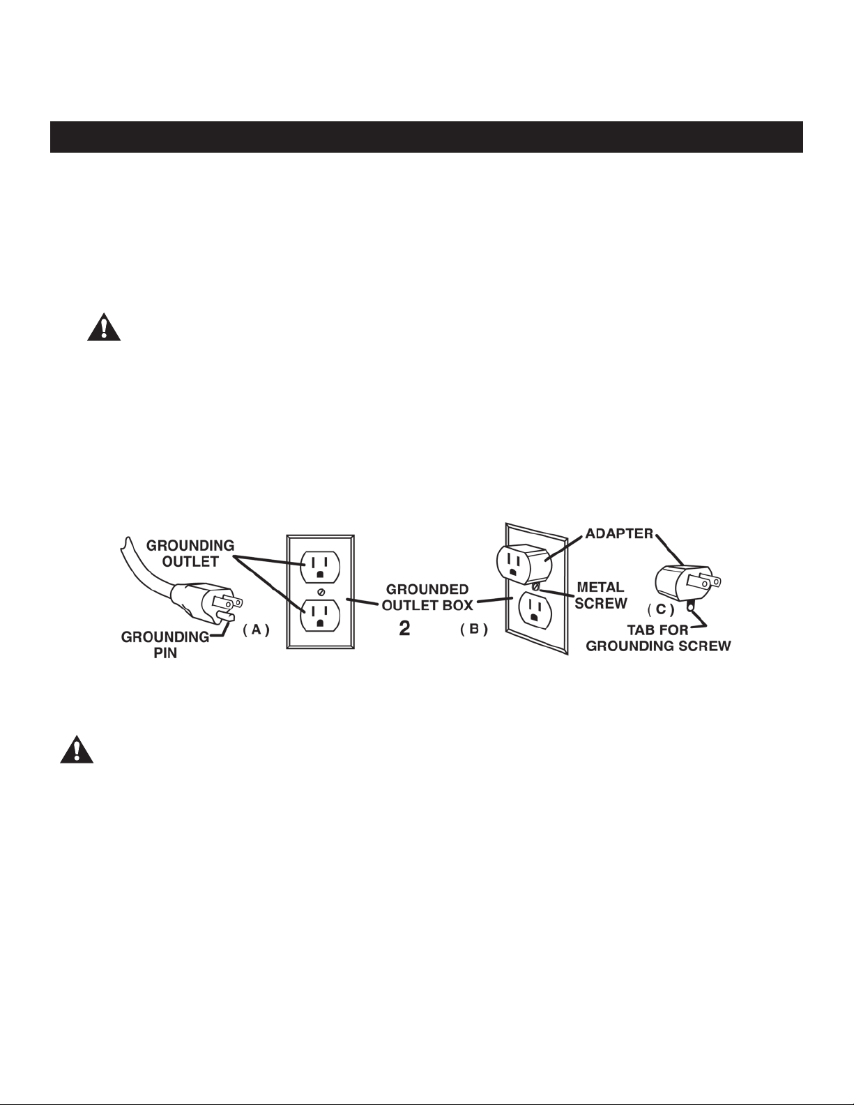
The equipment is for use on a nominal 120-volt circuit, and have a grounded plug that looks like the plug illustrated
in Figure A. A temporary adapter that looks like the adapter illustrated in Figure B and C may be used to connect this
plug to a 2-pole receptacle as shown in Figure B if a properly grounded outlet is not available. The temporary adapter
should be used only until a properly grounded outlet (Figure A) can be installed by a qualified electrician. The green
colored rigid ear, lug, or the like, extending for the adapter must be connected to a permanent ground such as a
properly grounded outlet box cover. Whenever the adapter is used, it must be held in place by a metal screw.
Note: In Canada, the use of a temporary adapter is not permitted by the Canadian Electrical Code.
The replacement or repair of damaged wiring should only be performed by a qualified
electrician or service engineer from the manufacturer or authorized service center.
GroundInG InstructIons
Improper connection of the equipment-grounding conductor can result in a risk of
electric shock. Check with a qualified electrician or service person if you are in doubt
as to whether the outlet is properly grounded. Do not modify the plug provided with
the appliance. If it will not fit the outlet, have a proper outlet installed by a qualified
electrician.
WARNING!
WARNING!
CONNECT TO A PROPERLY GROUNDED OUTLET ONLY!
See Grounding Instructions

6
Vacuum Inlet
Recovery Tank
Hard Surface Tool
Wand Holder Clip
Solution Line
Wand Holder
Solution and
Vacuum Hose
P.S.I. Gauge
Pressure Control
GENERAL DIAGRAM

7
Loading Wheels
Autodump Outlet
Autodump Circuit
Breaker
Autodump Switch
Pump Switch
Vacuum Switch
Transport
Wheels
Cord Hook
Manual Dump
Hose
Dual Circuit
Indicator
Solution Line Inlet
GENERAL DIAGRAM

8
CLEANING WITH THE HARD SURFACE TOOL
OPTIONAL: CLEANING CARPET WITH A CARPET WAND (Not Included)
OPTIONAL: USING A PRESSURE WASHER ATTACHMENT (Not Included)
PREPARING THE CLEANING AREA
MACHINE SET UP
This machine is designed as a direct feed solution system with a recovery tank with the option to auto dump.
To set up your machine:
GENERAL INSTRUCTIONS
1. Make sure hoses are in good condition and spray nozzle on wand is tight.
2. To prep your direct feed solution system, connect the machine to the water source with a garden hose.
3. When not using the auto-dump feature, make sure the brass cap is screwed tightly on the hose connector tting
on the dump pump on the rear of the machine. If using the auto-dump feature, connect the dump hose to the
brass hose tting on the back of the dump pump and place the open end of the hose in a drain. Make sure the
drain hose (recovery tank) is closed, and the lid is tight on the recovery tank.
4. Connect the vacuum hose to the wand.
5. Plug each extension cord into a separate and grounded 15 amp wall socket circuit. The green separate circuit
light will be lit. If the light does not come on, check the circuit breaker box on the wall, and/or try different outlets
until it does turn on.
6. Prime the pump: Ensure that the pump, vacuum and auto dump switches are off. Prime the pump by squeezing
the trigger on the wand to release the water. When a steady ow of water goes through, then your machine is
ready to be used.
7. Turn the vacuum and pump switch to on. If using the auto dump feature, turn on the autodump switch.
8. To adjust the pressure, while the trigger is activated on the hard surface tool with the pump switch on, adjust the
pressure unloader next to the PSI gage between 400-1200 PSI.
1. It is suggested to sweep the area to be cleaned prior to operating the machine.
2. Pre-Spray – with the use of a pump-up sprayer, pre-spray the oor with an approved hard surface pre-spray deter-
gent. Only use commercially available oor cleaners intended for machine application. Follow proper mixing and
handling instructions on the detergent bottle.
1. Verify the vacuum hose and solution hose are securely connected to the machine and hard surface tool.
2. Ensure the relief valve on the hard surface tool is closed. If the hard surface tool starts to stick to the oor due to
excessive vacuum pressure, slide the suction relief valve to adjust the pressure located at the head of the unit.
3. Turn on the pump and vacuum switches. Turn on the Auto-Sump switch if using this feature.
4. For optimum cleaning results pull trigger while moving the hard surface tool in a front to back motion.
Note: Use defoamer with each use to prevent vacuum ooding.
5. When nished with the job, shut off all switches. Before disconnecting solution hose, relieve the water pressure from
the hard surface tool by holding the trigger on the hard surface tool.
1. Verify the vacuum hose and solution hose are securely connected to the machine and carpet wand.
2. Set the PSI to no more than 800 psi to clean carpet. CAUTION: Damage to carpet may occure if the PSI is set
too high.
3. When nished with the job, shut off all switches. Before disconnecting solution hose, relieve the water pressure from
the carpet wand by holding the trigger on the carpet wand.
1. Verify the vacuum hose and solution hose are securely connected to the machine and pressure washer spray wand.
2. Set the PSI to the desired pressure between 400-1200 PSI.
3. When nished with the job, shut off all switches. Before disconnecting solution hose, relieve the water pressure from
the pressure washer spray wand by holding the trigger on the pressure washer spray wand
WARNING!
TO AVOID SERIOUS INJURY, NEVER POINT SPRAY NOZZLE
AT YOURSELF, OTHER PERSONS OR ANIMALS!
9
OPTIONAL: DRYING YOUR FLOOR WITH SQUEEGEE TOOL (Not Included)
DRAINING RECOVERY TANK
MAINTENANCE
STORING
GENERAL INSTRUCTIONS
1. Verify the vacuum hose is securely connected to the machine and wand. Connect the squeegee tool to the wand.
2. Turn on the vacuum switch to vacuum excess water.
1. Turn off all switches.
2. Drain the recovery tank by holding the end of the drain hose with the cap above the machine. Remove the cap on
the drain hose. Lower the drain hose over a drain or a bucket to drain the recovery tank.
Note: When using the Auto Dump feature, the recovery tank must be rinsed and then drained with the drain hose after
each use.
To keep the machine in good working condition, maintenance procedures should be followed after each use.
CAUTION: When servicing machine turn the power off and unplug the machine from the wall outlet.
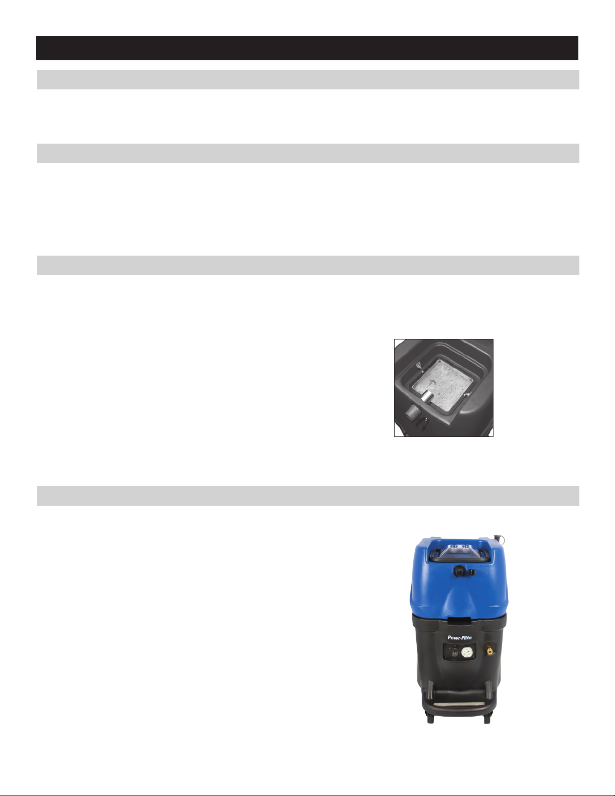
1.Drain and flush the recovery tank, intake hoses, and any wand or hand tool used with clean water. Make sure the
discharge connector is closed.
2.Thoroughly clean the inlet basket filter.
3.Inspect power cords for damage. Replace damaged cords and plugs
immediately. Do not use the machine with a damaged cord or plug.
4.Inspect vacuum hoses for holes and loose cuffs.
5.Clean machine housing with an all purpose cleaner and damp cloth.
6.Inspect the machine for leaks and loose hardware.
7.Lubricate wheels and casters with oil or grease .
8. Check and clean inlet filter
1.Machine should be completely empty and dry before storing.
2.Store machine in a dry area in the upright position.
3.Open recovery tank cover to promote air circulation.
CAUTION: Do not expose to rain or freezing temperatures, store indoors.
10
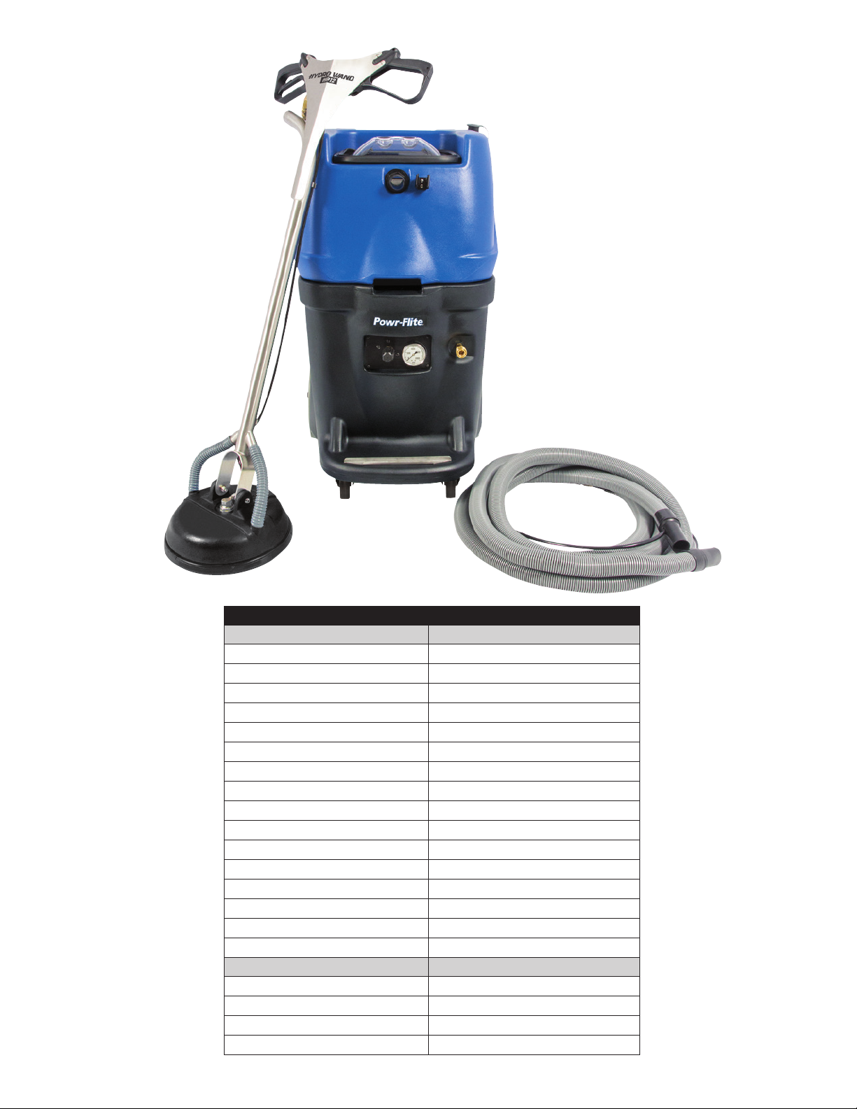
PRODUCT SPECIFICATIONS
MODEL
PFX1200RT
Power Cord 25 ft. 12 gauge, 3-wire (2)
Water Supply Hose 25 ft (2)
Recovery Tank Capacity 15 gallons
Vacumm Intake Hose 30 ft
Water Lift 135 in
CFM 92
Front Wheel Size 4 in
Rear Wheel Size 12 in
Tank Construction Polyethylene
Overcharge Protection Electronic oat / auto ON-OFF
Discharge Pump Self-priming impeller pump
Discharge Rate 5 GPM
Filter System Stainless Steel Filter
Weight 158 lbs
Dimensions 41"H x 29" L x 22" W
Warranty 10 years housing, 1 year motor
MODEL
HYDRO WAND HP-12
Head Diameter 15"
Spray jets 2 x 90 degree
Rated PSI 2600
Max Flow Rate 2.2 GPM

11
PROBLEM CAUSE SOLUTION
Poor pick up. Inlet basket filter is clogged. Clean filter.
Loose drain hose connection. Tighten drain hose.
Loose recovery tank lid. Position the lid correctly.
Damaged hose. Replace hose.
Suction relief is open on wand. Adjust or close suction relief on wand.
Vacuum motor does not operate Unplugged cord. Check connection to pigtail and wall
Faulty switch or loose wiring. Contact Service Center.
Tripped building circuit breaker. Reset breaker.
Defective vacuum motor. Contact Service Center.
Recovery tank is full. Empty the recovery tank.
Discharge pump does not operate Unplugged cord. Check connection to pigtail and wall
Faulty switch or loose wiring. Contact Service Center.
Tripped building circuit breaker. Reset breaker.
Defective vacuum motor. Contact Service Center.
Recovery tank is not full enough. Discharge pump will turn on when
there’s enough water in the recovery
tank.
Amount of discharge water dwindles. Worn impeller. Contact Service Center.
1200 PSI pump does not operate or has
low pressure.
Unplugged cord. Check connection to pigtail and wall.
Faulty switch or loose wiring. Contact Service Center.
Tripped building circuit breaker. Reset breaker.
Defective PSI pump. Contact Service Center.
Tripped pump circuit breaker. Reset breaker on PSI pump.
TROUBLESHOOTING
12
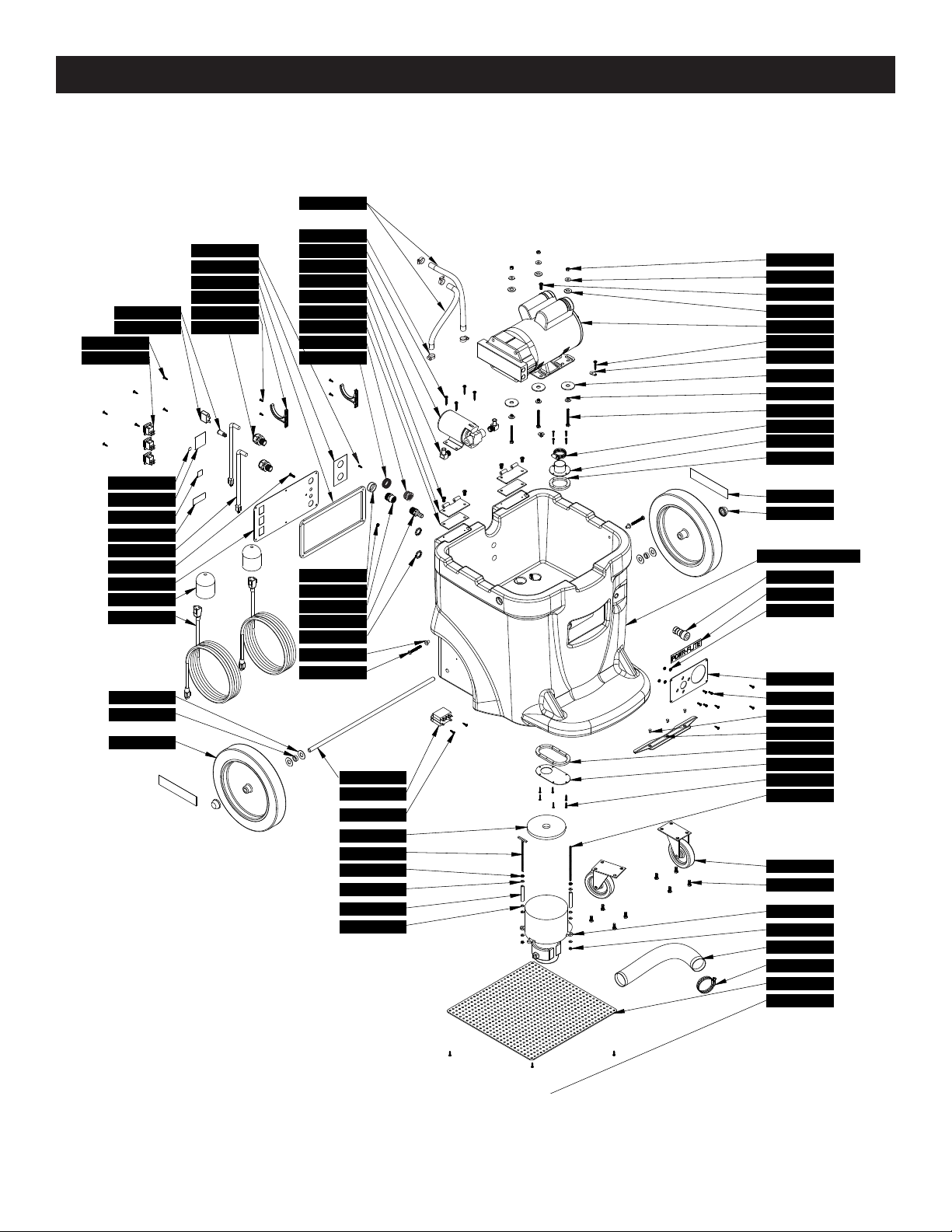
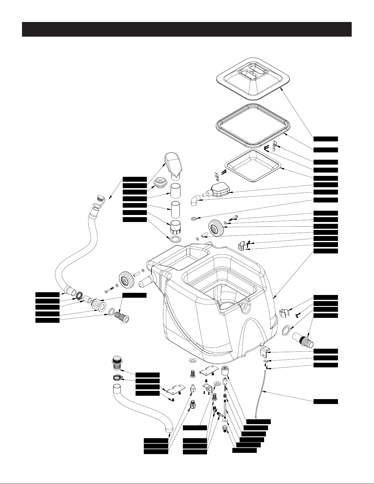
MODEL PFX1200RT PARTS
7DL008 X4
70079C
7CZ001
17850
18666
32966
71379A
71507A
71639A
71644A
72000A
72365B
72387A
72388A
72620ABREPRO
72625A
72630A
72632C
72633A
72635A
72636A
72641A
72642A
72661B
72662A
72665A
72684A
72820A
7BF003
7BF008
7BF030
7BS003
7CM007
7CW002
7DL005
7DT001
7EW001
7GL002
FP8
M1374 PC25
PD8
PX112
PX154
X1442
PX215
PX6
PX65
PX86
X1003
X1278
X1316
X1334
X1335
X1336
X1341 X4
X1367
X1368
X8261
X8008N
X8212
X8213
X8235
X8256
X8278
X8272
X8459
X8851
X8976
X9014
X9045A
X9066
X9069
X9079
X9098
X9168
X9204
X9214
X9253
X9324
X9687
X9718
72387A
PFX1200RT base assembly

13
MODEL PFX1200RT PARTS
PFX1200RT base assembly
PART NO. DESCRIPTION QTY
NEEDED
17850 WASHER PLAIN 6
18666 WASHER PLAIN .5” ID 3
32966 SWITCH ROCKER 3
70079C BULK HOSE 1/2” WIRE
REINFORCED 38″
71379A RELAY 25A 120V 1
71449A BAG, CORD WRAP FOR SHIPMENT 2
71507A ELBOW 1/2 H - 3/8 MPT 2
71639A 1/4-20 X 1-1/2 BOLT 3
71644A SCREW #10 X1 PHIL PAN SS 1
72000A 10/24 5-1/2 THREADED ROD SS 1
72365A VAC 3 STAGE 120V 1
72387A SCREW #8 X 5/8 BLACK PHIL PAN
TAPPING 12
72388A SCREW #10 X 5/8 4
72620ABREPRO BASE BLACK 1
72625A COVER VACUUM MANIFOLD 1
72630A COVER VACUUM MANIFOLD FLAT 1
72632C SWITCH PANEL RIPTIDE 1
72633A AXLE 1/2” DIA 1
72635A SPACER 1/2” ID X 3/4” OD X 1/4”
LONG 2
72636A COVER BASE BOTTOM 1
72641A GASKET VAC MANIFOLD SHORT 1
72642A GASKET VAC MANIFOLD 1
72661B WAND HOLDER PFX1350/PRO500 1
72662A SCREW #10 X 1/2” PHIL BLACK 3
72665A INSERT TEE NUT 1/4-20 THREAD 2
72684A SCREW 1/4 - 20 X 2 - 1/2 2
72820A 1/8” SPACER 2
7BF003 NUT KEPS #10-24 2
7BF008 NUT 10-32 KEPS SS 1
7BF030 NUT 10-24 NYLOC INSERT SS 2
7BS003 SCREW 1/4-20 X 1/2 PHIL PAN SS 4
7CM007 WASHER 1/2 FLAT SS 4
7CW002 SCREW #6 X 3/4 PHIL PAN SS 10
7CZ001 HOSE, VACUUM 2” DIAMETER BULK 20″
7DL005 CLAMP 1-1/2 1
7DL008 CLAMP 1-1/2 WORM GEAR
STAINLESS HEX 1
7DT001 BOLT 4/16 - 18 X 5/8 8
7EW001 1/4-20x 3/4 PHIL PAN 1
7GL002 NUT PUSH 1/2” 2
FP8 CAP WITH CHAIN 1
M1374 12/3 SJTW 25’ EXT CORD 2
PC25 BARB 1/2” X 1/2” MALE/MALE 1
PD8 STRAIN RELIEF 1/2 NPT 2
PART NO. DESCRIPTION QTY
NEEDED
PX112 CORD PIGTAIL 12/3 SJT 2
PX154 GARDEN HOSE FITTING 1
PX215 CLAMP 2 21/2” WORM GEAR 1
PX6 COUPLER FEMALE 1/4” 1
PX65 CASTER 4” BLACK 2
PX86 GREEN LIGHT INDICATOR 1
X1003 MADE IN THE USA LABEL 1
X1278 PUMPTEC PUMP WITH PLUMB 1
X1316 GASKET CONTROL PANEL 1
X1334 PRESSURE REGULATOR PLATE 1
X1335 HOSE THREAD 3/4” PIPE THREAD 1
X1336 RIPTIDE LABEL 2
X1341 KNOCK NUT 1/4-20 4
X1367 BOOT COVER FOR PLUG 2
X1368 LABEL HOSE INLET OUTLET 1
X1369 RIPTIDE WIRING HARNESS 1
X1442 FILTER, GARDEN HOSE INLET 1
X8008N NUT LOCK 1/2” STEEL 2
X8212 WASHER-LOCK (1/4”) 3
X8213 NUT 1/4-20 HEX FINISH ZINC 3
X8235 WASHER 1/4 FLAT 3
X8256 NUT 8-32 KEPS ZINC 4
X8261 KICKSTAND SCREW 5
X8272 SCREW 8-32 X 1/2 TRUSS 4
X8449 POWR-FLITE WARRANTY CARD 1
X8451 LABEL, PLAIN BOX 4 X 6 1
X8459 LABEL, SERIAL NUMBER, PLAIN 1
X8460 QUALITY CONTROL TICKET GREEN 1
X8851 SCREW, 10-32 x 1 MACHINE PH 1
X8976 LABEL, WARNING 1
X9014 TANK HINGE 2
X9045A SPACER VAC MOTOR 3 STAGE 2
X9066 WHEEL 12 X 1-3/4 NON MARKING
GRAY TIRE 2
X9069 END LOOP SS WITH TWO HOLES 1
X9079 GASKET 3/8” DONUT MOTOR SEAL 1
X9098 SCREW A PONIT #10 X 1 BLACK
ZINC 4
X9168 SPACER PAN HINGE 2
X9204 ROD 10-24 T BOLT SS 1
X9214 LABEL, GROUND SYMBOL 1
X9253 PUMP 1/10HP 360GPH SELF
PRIMING 1
X9324 5 AMP CIRCUIT BREAKER 1
X9687 POWR-FLITE LABEL 1
X9718 CORD HOOK 2
14
MODEL PFX1200RT PARTS
72656A
72660A
X9224 PC49
PX85
72645A
72173A
X9239
72326A
X9236
PX48
PX25
X9213
X9221
7DL005
PAS37
72666A
72631A
PAS36
7BH004
72388A
71644A
7BS003
72486A
PD8
X9014
72619BU
PX63
72615A
72677A
72680A
72679A
72323B
72321A
X9154
72678A
PX33
PX14 X8235
72274A
72115A
X8025
7AJ004
X9069
PX48G
70343A
7DA001
71328A
PX14A
7DL005
72173B
7BH004
72799B
PFX1200RT recovery tank assembly
15
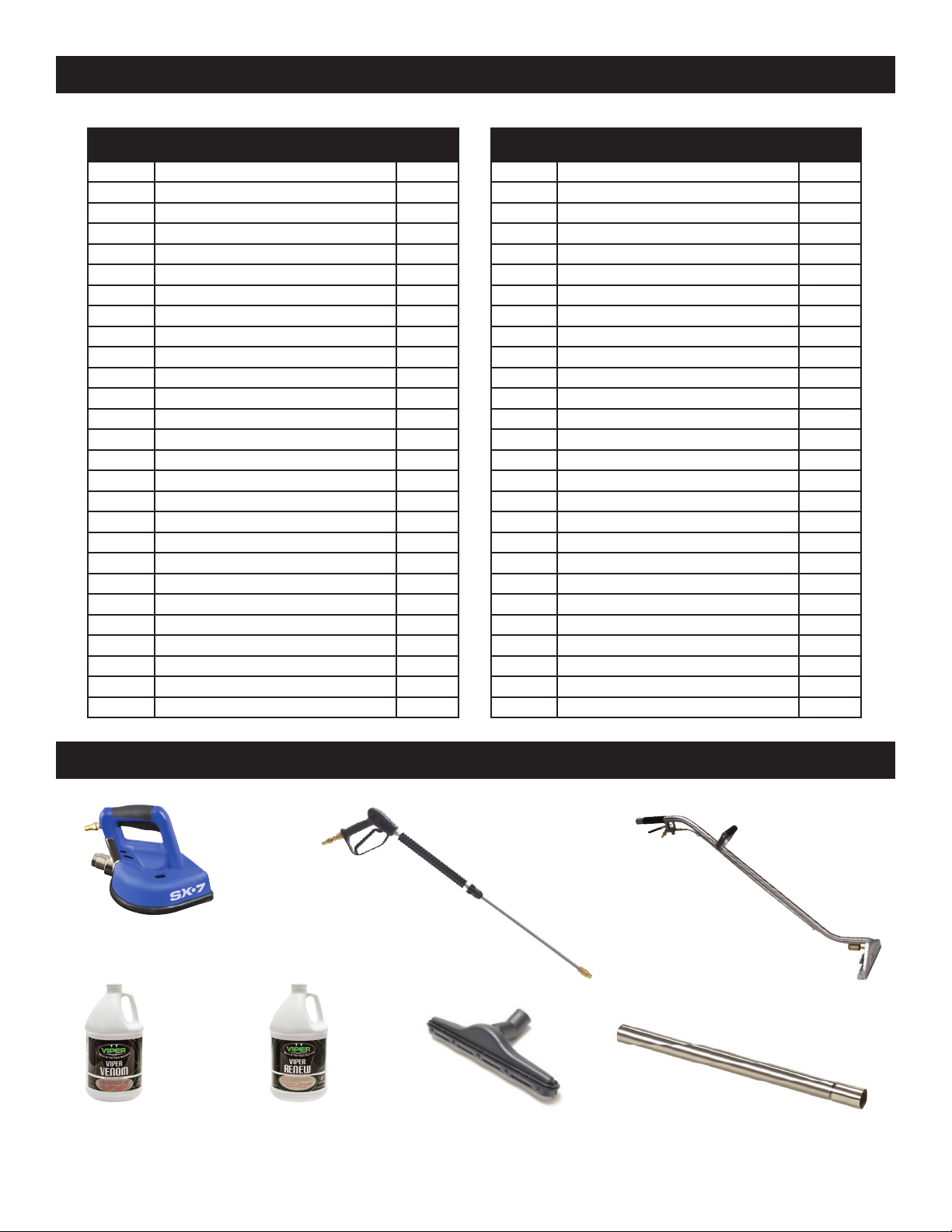
MODEL PFX1200RT PARTS
OPTIONAL ACCESSORIES NOT INCLUDED
PFX1200RT recovery tank assembly
PART NO. DESCRIPTION QTY
NEEDED
70343A SWITCH FLOAT 2 POLE 1
71328A SHIELD FLOAT SWITCH 1
71644A SCREW #10 X1 PHIL PAN SS 4
72115A WASHER 5/8 X 1-3/16 BONDED SEAL 1
72173A CLIP SPRING 1
72173B PIVOTING TOOL HOLDER 1
72274A WASHER 3/4” NEOPRENE BOND 2
72321A LID TANK 1
72323B GASKET LID 1
72326A FILTER INLET 1
72388A SCREW #10 X 5/8 4
72486A SPACER 1.625 LONG .5 OD 2
72615A COUPLING PVC 1-1/2 1
72619BU TANK RECYCLING BLUE 1
72631A LATCH BRACKET 2
72645A BOLT 5/16-18 X 2-1/4 2
72656A BLACK 1-1/2 WIRE-REINFORCED HOSE 32″
72660A ROPE SOLID BRAID 27″
72663A BOX, 41 X 24.5 X 37.5 1
72664A INSERT, BOX, 24.25 X 71 1
72666A INLET FITTING SHORT 1
72677A DRAIN FITTING 1” 1
72678A TUBING VINYL 1” ID 1
72679A GASKET INNER DRAIN 1
72680A GASKET DRAIN OUTER 1
72799B 5” LONG 1/8” THREADED PIPE 1
7AJ004 ANCHOR CONNECTOR 1/8 NPT 1
PART NO. DESCRIPTION QTY
NEEDED
7BH004 SCREW 10-32 X 3/8 PHIL PAN SS 4
7BS003 SCREW 1/4-20 X 1/2 PHIL PAN SS 4
7DA001 COUPLING 1/8-1/8 PIPE 1
7DL005 CLAMP 1-1/2 1
PAS36 PLUG DRAIN HOSE 1
PAS37 HOSE DRAIN 1
PC49 1/4” 90 DEGREE STREET ELBOW 1
PD8 STRAIN RELIEF 1/2 NPT 1
PX14 VALVE GASKET 1
PX14A VALVE GASKET 1
PX25 FITTING PLASTIC BULKHEAD 1
PX33 VACUUM TUBE 1
PX48 FITTING BRASS BULKHEAD 3/4” 2
PX48G GASKET FIBER 1
PX63 COUPLER PLASTIC 1-1/2” 1
PX85 BARB 1/4” X 3/8” MALE/MALE 1
X8025 WHEEL BLACK 4” X 1-1/4” 2
X8235 WASHER 1/4 FLAT 4
X9014 TANK HINGE 2
X9069 END LOOP SS WITH TWO HOLES 1
X9154 PIPE PVC 1
X9213 FLOAT SWITCH 1
X9221 HOLD DOWN LATCH FOR INLET FILTER 2
X9224 ADAPTOR 1/2 TO 1/4 NPT 1
X9236 FILTER VAC INLET PROTECTION 1
X9239 ELBOW PVC 1/2 NPT 1
X9874 SCOTCHWELD STRUCTURAL ADHESIVE 0.025
7" Spinner Hand Tool
Item# HP7
Wet/Dry Vac Wand
Item# WD29
(2 required)
Viper Renew
for restorative cleaning
Item# VR4
Viper Venom
for routine cleaning
Item# VV4
Wet/Dry Vac Tool
Item# WD30A
Pressure Washer Gun
Item# X1470
WonderWand™
1000 p.s.i., 3 jet
Item# WW1000

A Tacony Company
3101 Wichita Court • Ft. Worth, TX 76140-1755
1-800-880-2913 • Fax: 1-817-551-0719 • www.Powr-Flite.com
PFX1200RT-MAN 12/2015
Other manuals for PF1200RT
1
Table of contents
Other Powr-Flite Pressure Washer manuals

Popular Pressure Washer manuals by other brands

Kärcher
Kärcher HD 5/14 C Original instructions

Kärcher
Kärcher HDS 8/18-4 C manual

Clarke
Clarke PLV145H Operating & maintenance instructions

AR Blue Clean
AR Blue Clean AR112S Assembly, care and use instructions

Clarke
Clarke Power Wash KING 135 operating & maintenance manual

Nilfisk-ALTO
Nilfisk-ALTO Uno Booster operating instructions


