POWR2 POWRBANK PRO MKII User manual

For models:
POWRBANK PRO MKII
POWRBANK XPRO
customer[email protected]om
www.powr2.com
USA +1.800.354.4502
UK +44.330.128.9175
POWR2 POWRBANK User Manual V5.4 - 2022

WWW.POWR2.COM | POWRBANK USER MANUAL | 2
1 Introduction..............................................................................................................................4
1.1 Foreword...........................................................................................................................................................................................................4
1.2 Conventions....................................................................................................................................................................................................5
1.3 Warnings...........................................................................................................................................................................................................6
1.4 Disposal & Recycling.................................................................................................................................................................................7
1.5 POWR2 Contact Details..........................................................................................................................................................................7
1.6 About POWR2 ...............................................................................................................................................................................................7
2 Getting Started ........................................................................................................................ 8
2.1 Storage...............................................................................................................................................................................................................8
2.2 Transporting, Lifting and Positioning...........................................................................................................................................8
2.2.1 Transportation .............................................................................................................................................................................8
2.2.2 Lifting (Loading/Unloading)...............................................................................................................................................9
2.2.3 Positioning .....................................................................................................................................................................................9
2.3 The POWRBANK Control Panel ......................................................................................................................................................10
2.3.1 POWRBANK PRO EU Version .........................................................................................................................................10
2.3.2 POWRBANK PRO US Version........................................................................................................................................... 11
2.3.3 POWRBANK XPRO EU Version ...................................................................................................................................... 12
2.3.4 POWRBANK XPRO US Version....................................................................................................................................... 13
2.4 The Busbar Panel......................................................................................................................................................................................14
2.5 Connecting POWRBANK..................................................................................................................................................................... 15
2.5.1 Earth Connection .................................................................................................................................................................... 15
2.5.2 Input Options ............................................................................................................................................................................. 15
2.6 Connect the main AC Input............................................................................................................................................................... 16
2.6.1 Connecting by Hard-Wiring into the AC Input Busbar or CAM Terminals (US Version) ........ 16
2.6.2 Connecting by using the 125/3 CEE-Form Inlet (EU Version).................................................................... 16
2.7 Connecting to a Diesel Generator For Automatic Stop/Start..................................................................................... 17
2.7.1 Remote Generator Start Binding Posts Connection ...................................................................................... 17
2.8 Setting Up a Diesel Generator to Be Part of a Hybrid System................................................................................... 17
2.8.1 Common Causes of Diesel Generator Startup Delays ................................................................................... 17
2.9 Connect The AC Output.......................................................................................................................................................................18
2.9.1 Connecting by Hard-Wiring Into The AC Output Busbar or CAM Terminals.................................18
2.9.2 Connecting with CEE-Form output sockets.........................................................................................................18
3 General Operation .................................................................................................................19
3.1 Turning the Power On........................................................................................................................................................................... 19
3.1.1 Turn ON sequence.................................................................................................................................................................. 19
3.2 Turning the Power Off........................................................................................................................................................................... 19
3.2.1 Turn OFF sequence................................................................................................................................................................ 19
3.3 Emergency Stop Button ...................................................................................................................................................................... 19
3.4 Power Assist.................................................................................................................................................................................................20
3.5 Monitoring and Controlling the POWRBANK using ECM (Energy Control Module UI)........................... 21
3.5.1 HOME Screen............................................................................................................................................................................. 21
CONTENTS

3| POWRBANK USER MANUAL | WWW.POWR2.COM
3.5.2 MAINTENANCE CHARGE & SOLAR Screen......................................................................................................22
3.5.3 GENERATOR, Genset Timer & Information Screens ..................................................................................24
3.5.4 STORAGE & Energy Storage Information Screens......................................................................................26
3.5.5 LOAD, Load Auto Mode & Information Screens............................................................................................29
3.5.6 SYSTEM & System Information Screens.............................................................................................................32
3.5.7 SYSTEM Settings - Advanced settings for Genset, Battery & Global config............................. 34
3.5.8 SYSTEM ALARMS Screen............................................................................................................................................. 42
3.5.9 HISTORICAL Data ..............................................................................................................................................................43
3.5.10 NETWORK..............................................................................................................................................................................44
4 Care And Maintenance ...................................................................................................46
4.1 Charging the Unit: Caring For The Energy Storage ................................................................................................... 46
4.1.1 Performing Storage Maintenance........................................................................................................................ 46
4.1.2 Rotational Storage Maintenance ......................................................................................................................... 46
4.2 Servicing....................................................................................................................................................................................................47
4.2.2 Service Log............................................................................................................................................................................ 49
5 Safety & Protection...........................................................................................................50
5.1 Earthing POWRBANK..................................................................................................................................................................... 50
5.2 Safety Notice Regarding The Unit's Batteries................................................................................................................ 50
6 Predelivery and Post-Rental/Post-Hire Inspections.............................................. 51
6.1 Pre-delivery ..............................................................................................................................................................................................51
6.2 Post-Rental/Post-Hire Inspection............................................................................................................................................52
6.3 Default Settings ...................................................................................................................................................................................52
7 Troubleshooting................................................................................................................ 53
7.1 General Troubleshooting...............................................................................................................................................................53
7.2 Inverter LED indications and their meaning ...................................................................................................................55
7.3 Inverter VE.Bus Error Codes and their meaning ...........................................................................................................58
7.4 Alarm indicated by the LV Hub and Solution..................................................................................................................59
7.5 Alarm displayed on Battery Module US3000 ..................................................................................................................59
8 Sleep & Wake Procedures..............................................................................................60
8.1 Sleep Mode Procedure................................................................................................................................................................... 60
8.1.1 POWRBANK PRO ............................................................................................................................................................. 60
8.1.2 POWRBANK XPRO ............................................................................................................................................................61
8.2 Wake Procedure ..................................................................................................................................................................................62
8.2.1 POWRBANK PRO ..............................................................................................................................................................62
8.2 .2 POWRBANK XPRO ...........................................................................................................................................................63
9 Flat Batteries Recovery Procedure.............................................................................64
10 SIM Card Installation........................................................................................................ 65
10.1 US...................................................................................................................................................................................................................65
10.2 Rest of World..........................................................................................................................................................................................67

WWW.POWR2.COM | POWRBANK USER MANUAL | 4
1 INTRODUCTION
1.1 Foreword
Thank you for purchasing your POWR2 POWRBANK.
The POWR2 POWRBANK is rental ready power supply that integrates with diesel generator systems to
optimize efficiency and reduce noise, emissions and fuel waste.
ECM, the Energy Control Module is the brain of the unit, a touchscreen control panel enabling high-level
monitoring and control over the system.
POWR2 PORTAL, our Energy Management System (EMS) platform allows you to manage your fleet. It
enables you to monitor and report on each unit and the entire fleet at multiple levels to support the various
user groups you may have from end users to fleet manages to service engineers. POWR2 PORTAL provides
the very best means of managing your energy storage allowing you to get the most out of the system and
respond to your customers’ needs more effectively.
This manual will take you through the steps needed to own and operate this equipment safely and
effectively. You will also be able to manage and maintain the asset throughout its operational life.
POWR2 provides a one year return to base warranty on all its equipment. We offer various levels of service
contracts designed to suit your needs so please contact us about your requirements.
Thank you for choosing POWR2 and we look forward to working alongside you on this energy journey
towards a cleaner safer future.
5| POWRBANK USER MANUAL | WWW.POWR2.COM
1.2 Conventions
Throughout this user manual, the following symbols are used:
The following terms are used in this manual to provide greater clarity:
• POWR2 will be referred to as “The Manufacturer”.
• The POWR2 Hybrid Energy System will be referred to as “POWRBANK” or “Unit”.
• Any AC input or supply to the POWRBANK will be referred to as "AC source".
• Any items that consume power will be referred to as “Loads”.
• POWRBANK internal power electronics will be referred to as "Inverter"
• Solar Charge Controller will be referred to as "MPPT".
WARNING
This symbol warns of the presence of a dangerous voltage
which could cause harm to the operator or others.
This symbol indicates the potential of damage to the unit
or connected devices.
This symbol indicates important or useful information.
WWW.POWR2.COM | POWRBANK USER MANUAL | 6
1.3 Warnings
This user manual is an important part of POWRBANK. It
must be available to all operators and kept close to the unit
so that it can be referred to at any time.
WARNING
When the unit is operating it generates potentially lethal
voltages. Work must only be performed on the unit by the
manufacturer or a qualified service engineer approved by
the manufacturer.
All items connected to the unit including distribution
cables and boxes should be regularly checked and adhere
to the same local regulations and standards as a regular
grid-tied mains installation.

7| POWRBANK USER MANUAL | WWW.POWR2.COM
1.4 Disposal & Recycling
POWRBANK comprises of components that must be disposed of responsibly. For environmental purposes,
many of the components within the unit can be recycled or reused. POWR2 will ensure the safe
decommissioning and recycling of the unit at no charge if the unit is returned to the manufacturer.
Otherwise, please contact the manufacturer for more information on safe and proper decommissioning
of your POWRBANK.
1.5 POWR2 Contact Details
USA +1.800.354.4502
UK +44.330.128.9175
E-mail: customerservice@powr2.com
Web: www.powr2.com
1.6 About POWR2
POWR2 are dedicated to developing and marketing solutions that give our clients a competitive edge with
ground breaking offerings and new industry best practices. The POWRBANK has been designed by a team
of industry experts who have had 10 years’ experience in the renewable and energy storage sector.
POWR2 designs and builds Energy Storage Systems that seamlessly connect to solar PV, mains grid and
diesel generators to optimize performance and efficiency.
The team have engineered state of the art systems that are robust, cost effective and reliable. Over the
course of our evolution we have evaluated and tested countless designs, components and suppliers. We
currently manage a diverse and complex supply chain of over fifty manufacturers providing more than
one hundred and twenty separate components.
We apply strict quality control methods to every aspect of the process, from design, to procurement, to
manufacture, assembly and to testing.
The organization is built around our core values of efficiency, innovation, integrity and customer service of
which helps us create a long term sustainable business.
We believe that everyone wants to grow and become a better person. Our team is family, we want to
support, train, stretch and develop each one so they have the competitive advantage and are the winning
team.

WWW.POWR2.COM | POWRBANK USER MANUAL | 8
2 GETTING STARTED
2.1 Storage
1. The internal energy storage must be maintained while the unit is not in use. See “4.1 Charging
the Unit: Caring For The Energy Storage” on page 38.
2. POWRBANK is designed to be used and stored outside. However, it is recommended that the
unit is stored undercover when possible to prevent unnecessary weathering.
2.2 Transporting, Lifting and Positioning
2.2.1 Transportation
3. POWRBANK can be transported using a trailer or goods vehicle with adequate available payload.
Check the relevant transportation documentation for suitability.
4. The gross weight of the unit can be found on the rating plate positioned on the central front
door.
5. It is recommended that the unit is secured using suitable straps when in transit to prevent it
from moving.
WARNING
Powr2 offers no direct support for untrained individuals
carrying out any action on the unit. Please, contact Powr2
to request training.
It is the user's responsibility to check local
regulations for transport of POWRBANK as it contains
lithium-based batteries.
Be sure to double check the capacity of lifting equipment
before lifting the unit.

9| POWRBANK USER MANUAL | WWW.POWR2.COM
2.2.2 Lifting (Loading/Unloading)
1. POWRBANK must be loaded or unloaded using the correct equipment operated by suitably
trained personnel.
2. Using the fork pockets, POWRBANK can be loaded or unloaded with a suitable fork-lift truck or
telehandler.
2.2.3 Positioning
3. The unit must be positioned upright on a flat, solid surface. Ensure that the unit is not at risk of
being submersed in water above the fork pockets.
4. The unit should be positioned as close as possible to the chosen input source (e.g. diesel
generator) and where applicable, close to its earth point.
5. At least 3 feet should be allowed for ventilation on all sides of the unit.
6. Ensure that vents are not obstructed and heat sources are not directed at the unit.
Fig. 1 - Lifting Ring Warning
Always check the rating plate to ascertain the gross weight
of the unit.
Ensure that the exhaust and hot air flow of diesel
generators are directed away from POWRBANK.
The unit must remain upright at all times.
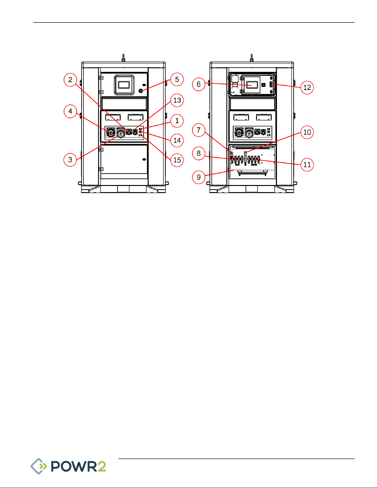
WWW.POWR2.COM | POWRBANK USER MANUAL | 10
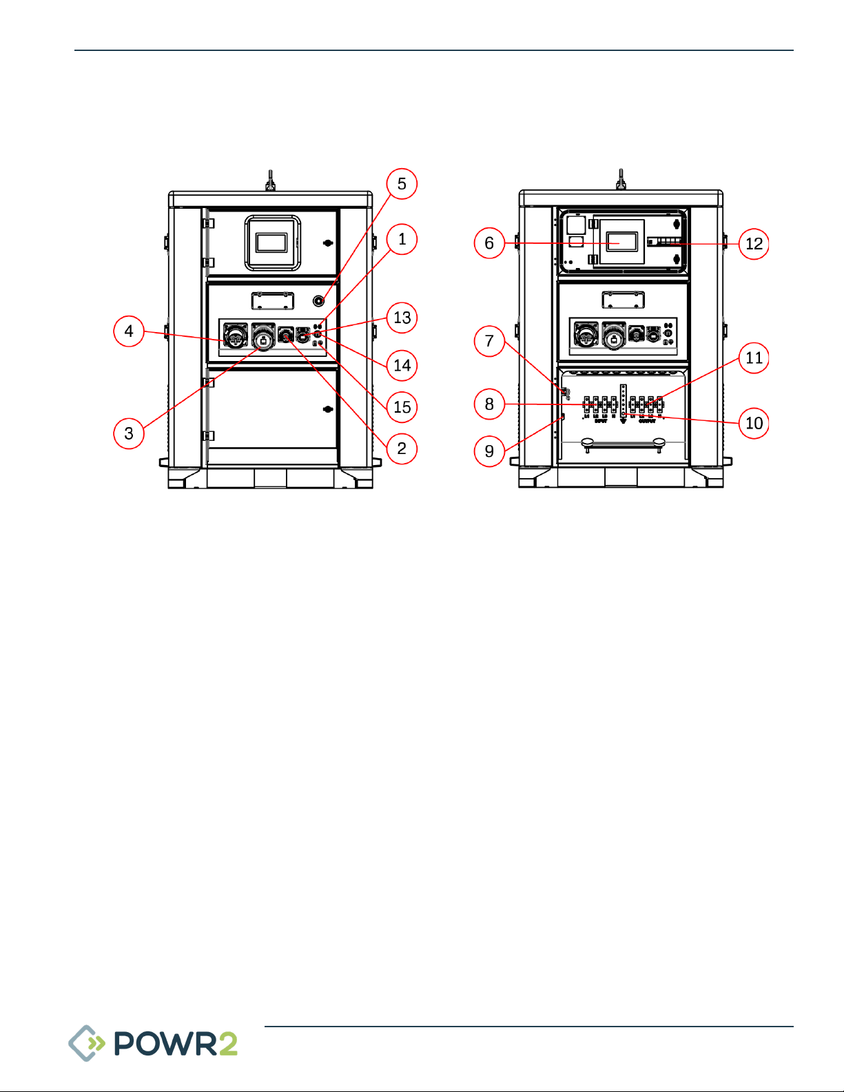
1. Generator Remote Start Binding posts for connecting wires to send start and stop signals to a
connected diesel generator (circuit is normally open).
2. Panel Mount CEE-Form Inlet 16A 230V maintenance charge inlet.
3. Panel Mount CEE-Form Outlet 125A 400V
4. Panel Mount CEE-Form Inlet 125A 400V
5. Emergency stop Press in to immediately shut down AC Output.
6. ECM The brain of the POWRBANK; interfaces with and controls the various system components
whilst data logging and connecting with the cloud platform.
7. Safety Limit Switch Switches off the AC Output when the bottom distribution door has been
opened.
8. AC Input Busbar Power Terminals
9. Generator RS485 Bus Terminals for connecting the RS485 Bus from a generator control panel to
the ECM.
10. Earth Busbar Earth Input/Output terminal for the unit.
11. AC Output Busbar Power Terminals
12. Output circuit breaker
13. Panel Mount CEE-Form Outlet 230V
14. RJ45 Connector (WAN)
15. MC4 Solar Input
2.3 The POWRBANK Control Panel
2.3.1 POWRBANK PRO (EU version)
Fig. 2 - EU Version Control Panel
11 | POWRBANK USER MANUAL | WWW.POWR2.COM
Fig. 3 - US Version Control Panel
2.3.2 POWRBANK PRO (US version)
1. Generator Remote Start Binding posts for connecting wires to send start and stop signals to a
connected diesel generator (circuit is normally open).
2. Emergency stop Press in to immediately shut down AC Output.
3. Nema 5-15P Maintenance Charge Inlet
4. ECM Controller The brain of the Powrbank; interfaces with and controls the various system
components whilst data logging and connecting with the cloud platform.
5. Safety Limit Switch Switches off the AC Output when the bottom distribution door has been
opened.
6. Input Busbar Power Terminals
7. Generator RS485 Bus Terminals for connecting the RS485 Bus from a generator control panel
to the ECM.
8. Output circuit breaker
9. Earth Busbar Earth Input/Output terminal for the unit.
10. Output Busbar Power Terminals
11. Input CAM Connectors
12. Output CAM Connectors
13. Nema 5-20R Outlet
14. RJ45 Connector (WAN)
15. MC4 Solar Input
WWW.POWR2.COM | POWRBANK USER MANUAL | 12
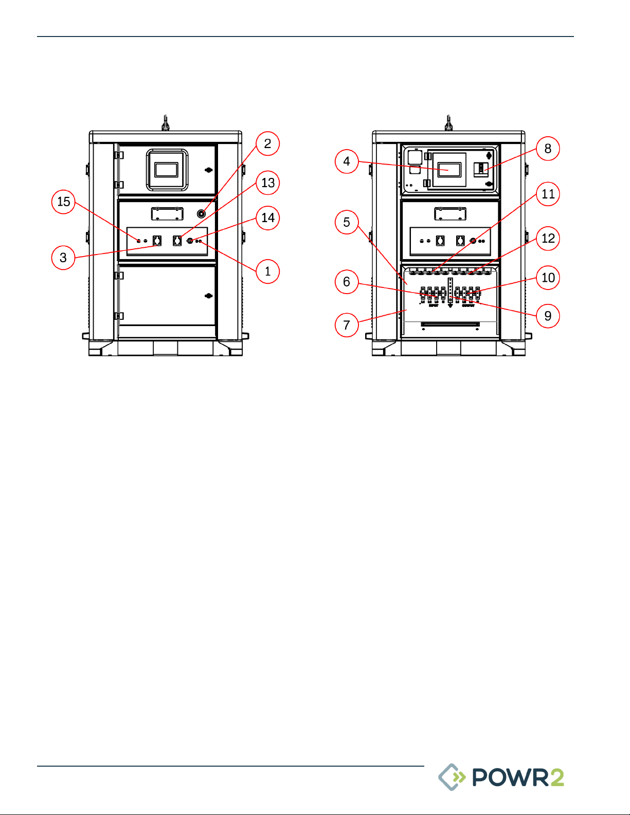
Fig. 4 - EU Version Control Panel
2.3.3 POWRBANK XPRO (EU version)
1. Generator Remote Start Binding posts for connecting wires to send start and stop signalsto a
connected diesel generator (circuit is normally open).
2. Panel Mount CEE-Form Inlet 16A 230V maintenance charge inlet.
3. Panel Mount CEE-Form Outlet 125A 400V
4. Panel Mount CEE-Form Inlet 125A 400V
5. Emergency stop Press in to immediately shut down AC Output.
6. ECM The brain of the POWRBANK; interfaces with and controls the various system components
whilst data logging and connecting with the cloud platform.
7. Safety Limit Switch Switches off the AC Output when the bottom distribution door has been
opened.
8. AC Input Busbar Power Terminals
9. Generator RS485 Bus Terminals for connecting the RS485 Bus from a generator control panel
to the ECM.
10. Earth Busbar Earth Input/Output terminal for the unit.
11. AC Output Busbar Power Terminals
12. Output circuit breaker
13. Panel Mount CEE-Form Outlet 16A 230V
14. RJ45 connector (WAN)
15. MC4 Solar Input

13 | POWRBANK USER MANUAL | WWW.POWR2.COM
Fig. 5 - US Version Control Panel
2.3.4 POWRBANK XPRO (US version)
1. Generator Remote Start Binding posts for connecting wires to send start and stop signals to a
connected diesel generator (circuit is normally open).
2. Emergency stop Press in to immediately shut down AC Output.
3. Nema 5-15P Maintenance Charge Inlet
4. ECM Controller The brain of the Powrbank; interfaces with and controls the various system
components whilst data logging and connecting with the cloud platform.
5. Safety Limit Switch Switches off the AC Output when the bottom distribution door has been
opened.
6. Input Busbar Power Terminals
7. Generator RS485 Bus Terminals for connecting the RS485 Bus from a generator control panel
to the ECM.
8. Output circuit breaker
9. Earth Busbar Earth Input/Output terminal for the unit.
10. Output Busbar Power Terminals
11. Input CAM Connectors
12. Output CAM Connectors
13. Nema 5-20R Outlet
14. RJ45 connector (WAN)
15. Solar MC4 Connectors
16. 480V output Busbar Power terminals
WWW.POWR2.COM | POWRBANK USER MANUAL | 14
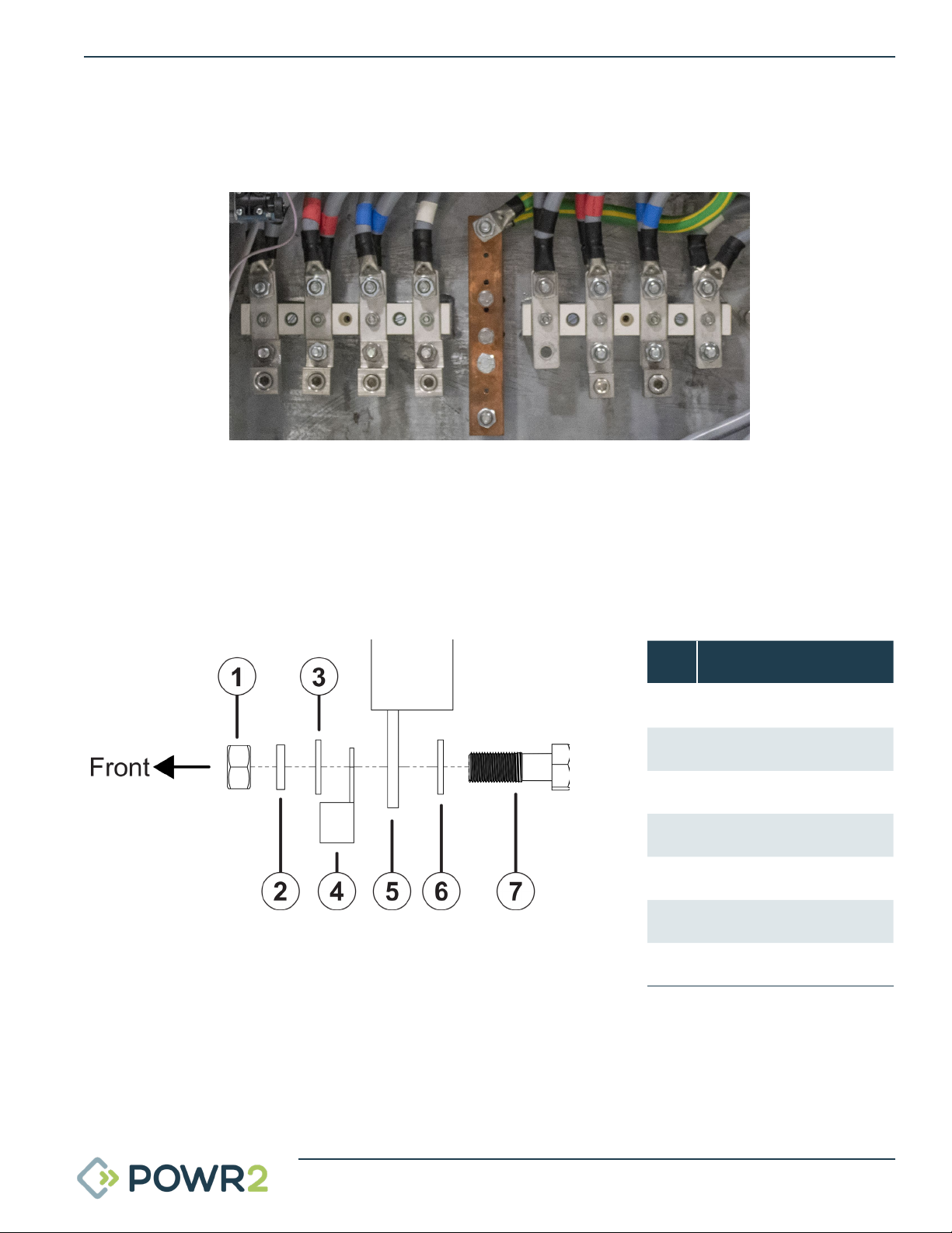
2.4 The Busbar Panel
The Busbar panel is located behind the lower distribution door. It is accessed by opening the lock at the
right of the door.
1. AC Input Busbar - (L1,L2,L3,N) For attachment of 10 mm ring terminals.
2. Earth Busbar - Earth connection for 10 mm ring terminals.
3. AC Output Busbar - (L1,L2,L3,N) For attachment of 10 mm ring terminals.
NoItem
1 M10 Plain Nut
2 M10 Spring Washer
3 M10 Flat Washer
4 M10 Ring Terminal
5 Busbar
6 M10 Flat Washer
7 M10 Bolt
Fig. 6 - 3-Phase Busbar Panel (Listed left to Right)
Fig. 7 - Busbar Connection Diagram

15 | POWRBANK USER MANUAL | WWW.POWR2.COM
2.5 Connecting POWRBANK
2.5.1 Earth Connection
When the unit is connected to an AC source, a separate earth connection should not be connected to the
earth busbar, only when working as stand alone. Refer to “Fig. 3 - US Version Control Panel” on page
11.
2.5.2 Input Options
The unit can accept input from a 3-phase AC power source or a Split phase AC power source depending
on its configuration. Further information on connecting an AC Input is provided in section “2.6 Connect
the main AC Input” on page 16.
In Maintenance charge the AC Input current is limited automatically allowing the unit to be charged from
a single phase AC sources with lower current capacity.
WARNING
A protective earth must be connected to POWRBANK in
compliance with applicable local standards and
regulations.
WARNING
The unit will only accept a specific range of voltage
according to its configuration. If a higher voltage source is
used it could severely damage the system and this will
invalidate the product warranty!

WWW.POWR2.COM | POWRBANK USER MANUAL | 16
2.6 Connect the main AC Input
2.6.1 Connecting by Hard-Wiring into the AC Input Busbar or CAM Terminals
1. Ensure that the circuit breaker of the AC source being connected to the unit is switched OFF.
2. Turn inverters OFF on the ECM onboard screen by selecting OFF mode (Home tab-System OFF)
3. Switch OFF the output circuit breaker.
4. Open the lower distribution door. See “2.3 The POWRBANK Control Panel” on page 10.
5. The Input busbar is located centrally and is the left hand side set. Ensure power terminals are
dry; wipe off any excess moisture with an absorbent cloth. The Input CAM terminal set is located
at the bottom right corner and is the top set.
6. Attach the AC supply connectors to the inlet CAM connectors or ring terminals to input power
terminals.
7. Close the lower distribution door.
8. Turn the inverters ON on the ECM onboard screen by selecting Operation mode (Home
tabSystem ON).
9. Switch on the AC input’s power supply.
10. Switch ON the output circuit breaker.
2.6.2 Connecting by using the 125/3 CEE-Form Inlet
11. Ensure that the circuit breaker of the AC source being connected to the unit is switched OFF.
12. Turn inverters OFF on the ECM onboard screen by selecting OFF mode (Home tab-System OFF)
13. Switch OFF the output circuit breaker.
14. Attach the AC input source 125/3 CEE-Form in-line socket
15. Turn the inverters ON on the ECM onboard screen by selecting Operation mode (Home
tabSystem ON).
16. Switch ON the AC input’s power supply.
17. Switch ON the output circuit breaker.

17 | POWRBANK USER MANUAL | WWW.POWR2.COM
2.7 Connecting to a Diesel Generator For Automatic Stop/Start
A Remote Generator Start function is provided to automatically control a diesel generator. The Start and
Stop conditions are programmed using the ECM.
2.7.1 Remote Generator Start Binding Posts Connection
Remote Generator Start terminals are located on the bottom door. See “Fig. 2 - EU Version Control
Panel” on page 10 or “Fig. 3 - US Version Control Panel” on page 11. This is a connection that is used
to send a start or stop signal to a remote fuel powered generator using its auto-start lead.
2.8 Setting Up a Diesel Generator to Be Part of a Hybrid System
When setting up a hybrid system the overall performance of combining POWRBANK with the diesel
generator can be enhanced by making some simple adjustments to the diesel set.
In automatic mode some diesel sets will start and run as soon as a start signal is received, however some
have a number of delays which can hinder the diesel generator from starting up and generating power
as quickly as possible. These delays should be minimized wherever practical.
2.8.1 Common Causes of Diesel Generator Startup Delays
2.8.1.1 Start Delay
This delay allows for short "false start" signals and can be as long as five seconds, when used with the
hybrid unit it is important that the diesel generator starts immediately. Where possible this delay should
be removed.
2.8.1.2 Pre-Heat Delay, Safety On Timer & Warm Up Timer
Always try to reduce the delays to the minimum acceptable level.
2.8.1.3 Automatic Mode
Ensure diesel generator is switched to automatic mode.
WARNING
If the generator is not configured to the right voltage, this
will severely damage the unit and void the warranty.

WWW.POWR2.COM | POWRBANK USER MANUAL | 18
2.9 Connect The AC Output
NOTE: If the unit has been put into SLEEP MODE it will be necessary to WAKE the unit by following
the procedure in section 8.2
2.9.1 Connecting by Hard-Wiring Into The AC Output Busbar or CAM Terminals
1. Ensure that the circuit breaker of the AC source being connected to the unit is switched OFF.
2. Turn inverters OFF on the ECM onboard screen by selecting OFF mode (Home tab-System OFF)
3. Switch OFF the output circuit breaker.
4. Open the lower distribution door. See “2.3 The POWRBANK Control Panel” on page 10.
5. The Output busbar is located centrally and is the right hand side set. Ensure power terminals
are dry; wipe off any excess moisture with an absorbent cloth. The output CAM terminal set is
located at the bottom right corner and is the bottom set.
6. Attach the load connectors to the outlet CAM connectors or ring terminals to output power
terminals.
7. Close the lower distribution door.
8. Turn the inverters ON on the ECM onboard screen by selecting Operation mode (Home
tabSystem ON).
9. Switch on the AC input’s power supply
10. Switch ON the output circuit breaker.
2.9.2 Connecting with CEE-Form output sockets
11. Ensure that the circuit breaker of the AC source being connected to the unit is switched OFF.
12. Turn inverters OFF on the ECM onboard screen by selecting OFF mode (Home tab-System OFF)
13. Switch OFF the output circuit breaker.
14. Attach 125/3 CEE-Form in-line plug
15. Turn the inverters ON on the ECM onboard screen by selecting Operation mode (Home
tabSystem ON).
16. Switch ON the AC input’s power supply.
17. Switch ON the output circuit breaker.
19 | POWRBANK USER MANUAL | WWW.POWR2.COM
3 GENERAL OPERATION
3.1 Turning the Power On
NOTE: If the unit has been put into SLEEP MODE it will be necessary to WAKE the unit by following
the procedure in section 8.2
Once all connections are complete, the unit is ready to be switched on.
3.1.1 Turn ON sequence
Ensure that the lower distribution door is closed.
Switch ON the output circuit breaker (UP position).
Turn the inverters ON on the ECM onboard screen by selecting Operation mode (Home tab-System ON).
The load metrics can now be observed on the ECM and Powr2 Portal.
3.2 Turning the Power Off
When Power is not needed at the output, the unit can be turned off.
3.2.1 Turn OFF sequence
Turn inverters OFF on the ECM onboard screen by selecting OFF mode (Home tab-System OFF).
Switch OFF the input and output circuit breaker (DOWN position)
3.3 Emergency Stop Button
1. If there is an emergency and it is necessary to turn off the unit's power, press the Emergency
Stop Button on the Upper Control Panel Door.
2. The unit will then shut down and the main output breaker will trip. POWRBANK can not be
switched on again until the Emergency Stop Button is released by rotating it clockwise.
3. Once the problem has been rectified, follow the instructions in “3.1 Turning the Power On” on
page 19 to switch the power back on.
ONLY use the emergency stop button in an emergency.

WWW.POWR2.COM | POWRBANK USER MANUAL | 20
3.4 Power Assist
The Power Assist facility will activate automatically as required with no programming required by the
customer.
It will activate when the load demand rises above the input limit of the AC source, when activated the
inverter(s) will synchronize themselves with the AC source and add their power to the incoming power.
This function is useful when a high load demand is needed at intervals which the POWRBANK cannot
supply.
When using Power Assist please note that although there
is an incoming supply, the storage will be depleted whilst
Power Assist is being used. [Only in the condition that the
AC source is not big enough. If the AC source is big enough
then the storage would not be depleted.]
Please contact the manufacturer for further information.
This manual suits for next models
1
Table of contents
Popular Storage manuals by other brands


NetApp
NetApp DS4486 Installation and setup

Synology
Synology DS923+ product manual

Sony
Sony SDX-700C Product specifications manual

Hitachi
Hitachi Travelstar HTS542525K9SA00 Specifications

Western Digital
Western Digital WDG2TP10000N - My Book Pro Edition II Hard Drive... Product specifications

Seagate
Seagate BARRACUDA2, 2HP ST12450W/WD installation guide