Powrmatic WX Series User guide

Stamm International Corporation
PO Box 1929
Fort Lee, NJ 07024
Tel: 201-947-1700
Fax: 201-947-9662
E-mail: stamminc@pobox.com
Stamm International HQ
www.powrmatic.co.uk
www.powrmatic.co.uk
®
Powrmatic Limited
Hort Bridge, Ilminster
Somerset
TA19 9PS
tel: +44 (0) 1460 53535
fax: +44 (0) 1460 52341
e-mail: [email protected]
web: www.powrmatic.co.uk
Powrmatic Ireland
45 Broomhill Close
Tallaght
Dublin 24
tel: +353 (0) 1452 1533
fax: +353 (0) 1452 1764
e-mail: [email protected]
web: www.powrmatic.ie
Getting In Touch
Powrmatic pursues a policy of continues improvement in both design and performance of its products and therefore reserves the right to change, amend or
vary specifications without notice. Whilst the details contained herein are believed to be correct they do not form the basis of any contract and interested
parties should contact the Company to confirm whether any material alterations have been made since publication of this brochure.
EURO-AIR
QUALITY
ICOM
Energy Association
More information is available from our website by scanning the following QR code.
WX
User, Installation & Servicing Manual
Issue 1.0 Apr 2021
Doc Ref: M112 Issue 1.0Apr 2021

page no. 2 of 20
WX Aquamatic Unit Heater Doc ref: M112 issue 1.0 Apr 2021
www.powrmatic.co.uk
Important: This certificate
must be kept with the appliance
Failure to provide a copy of the commissioning sheet invalidates the heater warranty
----------------------------------------------------
Powrmatic Ltd, Hort Bridge, Ilminster, Somerset, TA19 9PS
Tel: 01460 53535 Fax: 01460 52341
This is to certify that this appliance is guaranteed for 12 months parts only from the date of original
commissioning. The heater must be commissioned within 4 weeks of installation.
To make a claim
In the first instance you must contact your appliance supplier, or installer and provide:-
1. The appliance type and serial number.
2. The original commissioning documentation. As much detail as possible on the fault.
3. Your supplier, or installer, will then contact Powrmatic to make a guarantee claim on your behalf.
Conditions of Guarantee
1. The heater must have been installed by a competent qualified installer, and in accordance with
the manufacturer’s instructions, building regulations and local regulations.
2. The heater has been professionally commissioned, within 4 weeks of installation, and a copy of
the commissioning sheet returned to Powrmatic.
3. The heater has been maintained on a yearly basis by a competent and qualified servicing
company.
4. The heater has been used in accordance with the manufacturer’s instructions.
5. The correct specification fuel has been used.
6. No unauthorised repairs of modifications have been made. Powrmatic ‘General Conditions of
Sales’ have been observed.
7. Except for the obligation of Powrmatic Ltd to perform warranty repairs during the guarantee
period, Powrmatic will not be liable in respect of any claim for direct or indirect consequential
losses, including loss of profits or increased cost arising from loss of use of the heater, or any
event arising there from.
Exclusions
Consumables such as links, control batteries are all excluded from guarantee.
Certificate of Guarantee
®
Certificate of Guarantee

page no. 3 of 20
WX Aquamatic Unit Heater Doc ref: M112 issue 1.5 Apr 2021
Title Section Contents Page
1. INTRODUCTION
1.1 Precautions, requirements, recommendations 4
1.2 Transport 4
1.3 Initial steps taken before installation 4
2. DESIGN, USE, PRINCIPLE OF OPERATION
2.1 Intended use 4
2.2 Principle of operation 4
2.3 Construction of the device 5
2.4 Overall dimensions 5
3. TECHNICAL DATA 6
4. ASSEMBLY 10
4.1 Installation with a bracket 11
4.2 Installation instructions 11
4.3 Installation instructions & mounting distances 12
5.AUTOMATIC DEVICES
5.1 Automatic devices 14
6. START-UP, OPERATION, MAINTENANCE
6.1 Start-up 14
6.2 Operation and maintenance 14
7. INDUSTRIAL SAFETY INSTRUCTION 14
8. WIRING DIAGRAMS 15
9. TECHNICAL INFORMATION TO THE REGULATION (EU) NO 327/2011
IMPLEMENTING DIRECTIVE 2009/125/EC 16
10. SERVICE
10.1 Procedures in case of defects 18
10.2 Complaint procedure 19
Users,InstallationandServicingInstructions
CONTENTS
Contents

1. INTRODUCTION
1.1 PRECAUTIONS, REQUIREMENTS, RECOMMENDATIONS
Read the documentation carefully, install and use the equipment according to the specifications, and follow all the safety regulations in order to ensure proper and safe use of the device. Any
use that is incompatible with these instructions can cause serious injuries. Restrict access by unauthorized persons and train the operational personnel. The term operational personnel refers
to people who are suitably trained and have appropriate experience and knowledge of relevant norms, documentation and occupational health and safety regulations, and are authorised to
conduct the required work and can identify possible threats and avoid them. This operation and maintenance manual, which is delivered with the device, includes detailed information on all
possible configurations of the heaters, examples of their assembly, start, use, repair and maintenance. To operate this device correctly, this manual includes instructions sufficient for qualified
personnel. The documentation should be placed close to the device for ease of access by the service team. The manufacturer reserves the right to introduce changes to the
manual or the specifications of the device, which may alter its operation, without prior notice. Powrmatic Limited shall not be held liable for current maintenance, servicing,
programming, damage caused by standstill of the device awaiting warranty service, any damage to customer’s possessions other than the device, or faults resulting from the wrong assembly
or use of the device.
1.2 TRANSPORT
Prior to the installing and taking the device out of the cardboard box, it is required to check whether the cardboard box has not been damaged in any way and/or the adhesive tape (installed
at the company) has not been broken off or cut. It is recommended to check whether the device’s casing has not been damaged in transport. Should any of the above situation occur, please
contact us through telephone or e-mail: Tel. 01460 53535 email: [email protected], fax: 01460 52351. The device should be transported by two people. Use appropriate
tools, when transporting the device, so as to avoid the damaging of goods and potential hazard to health.
1.3 INITIAL STEPS TAKEN BEFORE THE INSTALLATION
Record the serial number of the device in the warranty card, prior to the commencement of the installation process. It is required to properly fill-in the warranty card, after the completion
of the assembly. Prior to the commencing of any installation or maintenance work, it is required to disconnect power supply and protect it against unintentional activation.
2. STRUCTURE, INTENDED USE, PRINCIPLE OF OPERATION
2.1 INTENDED USE
Powrmatic WX has been designed to ensure ease of use and optimum performance.
The device is available in FOUR versions:
Powrmatic WX combines state-of-the-art technology, innovative design and high effectiveness. Unique technical solutions such as the design of the heat exchanger, improved fan and
increased range of air stream, allow the WX heater to achieve optimal heating power, perfect for the size and type of room. APPLICATION: production halls, warehouses, wholesale outlets,
sports facilities, greenhouses, supermarkets, church buildings, farm buildings, workshops, health care facilities, pharmacies, hospitals. It is allowed to use Powrmatic WX air heaters in rooms
with high humidity (without condensation) i.e. car washes, provided that the unit is not exposed to direct impact of the water strIt is allowed to use Powrmatic WX air heaters in rooms with high
humidity (without condensation) i.e. car washes, provided that the unit is not exposed to direct impact of the water stream. Prohibition of using Powrmatic WX air heaters in rooms with
aggressive environment (i.e. high concentration of ammonia) that can cause corrosion of aluminium or copper.
MAIN ADVANTAGES: high effectiveness, low maintenance costs, full parameter control, easy and quick assembly.
2.2 PRINCIPLE OF OPERATION
The heating medium (hot water) gives up heat to the heat exchanger using a highly developed heat exchanger, ensuring great heating power (Powrmatic WX-1-EC – 10.4-15.3 kW, Powrmatic
WX-2-EC – 15.6-22.0 kW, Powrmatic WX-3-EC – 24.2-36.7 kW, Powrmatic WX-4-EC – 36.7-55.0 kW). A highly effective axial fan (1100-5700 m3/h) draws air in from the room, pumps it
through the heat exchanger and then sends it back into the room. Powrmatic WX heater de-stratifies the heated air from the sub-ceiling zone to the above-ground zone. Hot air exhaust results
in a leveling of the temperature gradient in particular air layers and contributes to reducing the costs of heating by lowering the temperature in the ceiling zone, thus limiting heat loss through
the roof. Cooperation of these device types will allow for achieving optimal temperature comfort fast due to the support of the heating system through more efficient distribution of hot air.
Powrmatic WX-1-EC (10.4 - 15.3kW @ 80/60°C, 1100 - 2100m³/h)
Powrmatic WX-2-EC (15.6 - 22.0kW @ 80/60°C, 2800 - 5300m³/h)
Powrmatic WX-3-EC (24.2 - 36.7kW @ 80/60°C, 2400 - 4850m³/h)
Powrmatic WX-4-EC (36.7 - 55.0kW @ 80/60°C, 3000 - 5700m³/h)
page no. 4of 20 WX Aquamatic Unit Heater Doc ref: M112 issue 1.0 Apr 2021
Introduction
Marks L [mm]
A 700
B 700
C 355
D 550
E 350
F 550
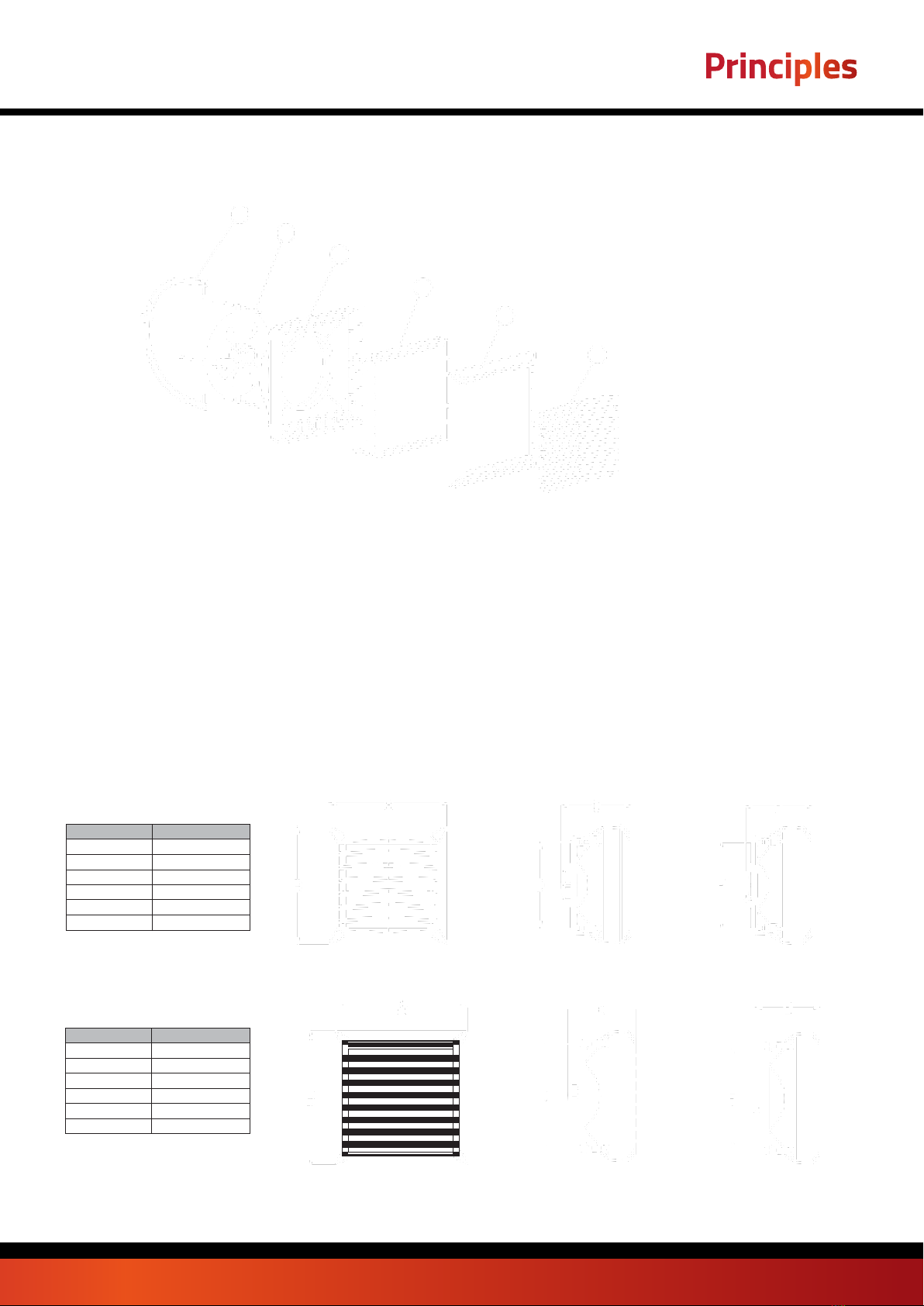
2.3 DEVICE STRUCTURE (Powrmatic WX)
1. HEAT EXCHANGER;
2. AXIAL FAN;
3. COVER;
4. AIR GUIDES;
5. SAMPLE CONSOLE
1. EN: HEAT EXCHANGER: maximum parameters of a heating medium for a heat exchanger are: 130°C, 1,6MPa. Aluminium and copper construction using copper tubes, coil pipe and
aluminium lamellas. Connecting ferrules (male thread ¾”) are on the back panel of the unit. Our series of types includes a single-row heat exchanger in the Powrmatic WX-2-EC – 15.6-22.0
kW and two-row heat exchanger in the Powrmatic WX-1-EC – 10.4-15.3 kW and Powrmatic WX-3-EC – 24.2-36.7 kW, Powrmatic WX-4-EC – 36.7-55.0 kW - three-row heat exchanger. The
glycol concentration in the heating medium can be up to 50%.
2. AXIAL FLOW FAN: maximum working temperature is 60°C, nominal power supply voltage is 230V/50Hz. AC Engine protection is IP54, insulation class F for EC motors IP is 54. Air feed is
performed by the axial flow fan, which i s secured with a protective grate. Adequate blade profile a nd proper bearings guarantee silent and unfailing operation o f the device. High engine
power allows for achieving high efficiency at low power consumption rates, maintaining full air feed regulation. Properly profiled housing lowers the noise emission levels, which makes the
device particularly user-friendly, suitable for buildings with higher acoustic requirements.
3. HOUSING: consists of the body and the front panel, made of high quality plastic guaranteeing compatibility with devices powered by heating medium with temperature parameter up to 130°C.
4. AIR GUIDES: allow the hot air stream to be directed in 4 directions. Optimum air stream range and direction are achieved through the special fan blade profile.
5. ASSEMBLY CONSOLE: an element of additional equipment - its ergonomic, light structure allows for rotating the device on the horizontal plane for -60°÷0÷60°, to direct the stream of hot air
wherever it is necessary.
2.4 OVERALL DIMENSIONS (Powrmatic WX-1-EC, WX-2-EC, WX-3-EC & WX-3-EC)
AC EC
Powrmatic WX-1-EC
Marks L [mm]
A 530
B 530
C 310
D 381
E 300
F 381
AC EC
Powrmatic WX-2-EC, WX-3-EC & WX-3-EC
5
2
3
1
3
4
page no. 5of 20
WX Aquamatic Unit Heater Doc ref: M112 issue 1.5 Apr 2021
Principles

3. TECHNICAL DATA
Tz – inlet water temperature; Tp – outlet water temperature; Tp1 – inlet air temperature; Tp2 – outlet air temperature; Pg – heating capacity; Qw – water flow; Qp- air flow rate; Δp –
pressure drop in the heat exchanger
Powrmatic WX-1-EC
Parameters Tz/Tp [°C]
90/70 [°C]
80/60 [°C]
70/50 [°C]
50/30 [°C]
Tp1
[°C]
Qp
[m³/h]
Pg
[kW]
Tp2
[°C]
Qw
[m³/h]
Δp
[kPa]
Pg
[kW]
Tp2
[°C]
Qw
[m³/h]
Δp
[kPa]
Pg
[kW]
Tp2
[°C]
Qw
[m³/h]
Δp
[kPa]
Pg
[kW]
Tp2
[°C]
Qw
[m³/h]
Δp
[kPa]
0
2100
20.7
29.5
0.92
13.9
17.9
25.4
0.79
10.7
15.1
21.4
0.66
7.9
9.2
13.1
0.4
3.4
1650
18.1
32.6
0.8
10.7
15.6
28.2
0.69
8.3
13.1
23.7
0.58
6.1
8
14.6
0.35
2.6
1100
14.1
38.3
0.63
6.8
12.2
33.2
0.54
5.3
10.3
27.9
0.45
3.9
6.3
17.2
0.28
1.7
5
1650
16.9
35.6
0.75
9.5
16.6
28.6
0.73
9.3
13.7
24.5
0.6
6.6
7.6
16.1
0.34
2.5
2100
19.4
32.6
0.86
12.3
14.5
31.1
0.64
7.2
12
26.6
0.53
5.2
6.8
17.4
0.3
2
1100
13.3
40.9
0.59
6
11.3
35.8
0.5
4.6
9.4
30.5
0.41
3.3
5.4
19.6
0.23
1.3
10
2100
18.1
35.7
0.8
10.8
15.3
31.7
0.67
8
12.4
27.6
0.54
5.5
6.4
19.1
0.28
1.7
1650
15.8
35.5
0.7
8.4
13.3
34.1
0.59
6.2
10.8
29.5
0.47
4.3
5.6
20.1
0.24
1.4
1100
12.4
43.5
0.55
5.3
10.4
38.3
0.46
3.9
8.5
33
0.37
2.8
4.4
21.9
0.19
0.9
15
2100
16.8
38.8
0.74
9.4
13.9
34.8
0.61
6.7
11
30.7
0.48
4.4
4.9
22
0.22
1.1
1650
14.6
41.4
0.65
7.3
12.1
37
0.54
5.2
9.6
32.4
0.42
3.5
4.3
22.8
0.19
0.9
1100
11.5
46.1
0.51
4.6
9.5
40.9
0.42
3.3
7.6
35.5
0.33
2.2
3.3
24.1
0.15
0.5
20
2100
15.5
41.9
0.69
8
12.6
37.9
0.56
5.6
9.7
33.7
0.42
3.5
3.3
24.7
0.14
0.5
1650
13.5
44.3
0.6
6.2
11
39.8
0.48
4.3
8.4
35.2
0.37
2.7
2.8
25.1
0.12
0.4
1100
10.6
48.6
0.47
4
8.6
43.4
0.38
2.8
6.6
38
0.29
1.8
1.9
25.2
0.08
0.2
Tz – inlet water temperature; Tp – outlet water temperature; Tp1 – inlet air temperature; Tp2 – outlet air temperature; Pg – heating capacity; Qw – water flow; Qp- air flow rate; Δp –
pressure drop in the heat exchanger
Powrmatic WX-2-EC
Parameters Tz/Tp [°C]
90/70 [°C]
80/60 [°C]
70/50 [°C]
50/30 [°C]
Tp1
[°C]
Qp
[m³/h]
Pg
[kW]
Tp2
[°C]
Qw
[m³/h]
Δp
[kPa]
Pg
[kW]
Tp2
[°C]
Qw
[m³/h]
Δp
[kPa]
Pg
[kW]
Tp2
[°C]
Qw
[m³/h]
Δp
[kPa]
Pg
[kW]
Tp2
[°C]
Qw
[m³/h]
Δp
[kPa]
0
5300
29.9
16.8
1.33
26
25.8
14.5
1.14
20
21.7
12.2
0.95
14.6
13.2
7.5
0.58
6.2
3900
25.4
19.4
1.12
19.1
21.9
16.7
0.97
14.7
18.4
14.1
0.81
10.8
11.3
8.6
0.49
4.6
2800
21.2
22.6
0.94
13.6
18.3
19.5
0.81
10.5
15.4
16.4
0.68
7.8
9.4
10.1
0.41
3.3
5
5300
28
20.8
1.24
23
23.9
18.4
1.05
17.3
19.7
16.1
0.87
12.3
11.3
11.3
0.49
4.6
3900
23.8
23.2
1.05
16.9
20.3
20.5
0.9
12.8
16.8
17.8
0.74
9.1
9.6
12.3
0.42
3.4
2800
19.9
26.2
0.88
12.1
16.9
23.1
0.75
9.1
14
19.9
0.62
6.6
8
13.6
0.35
2.5
10
5300
26.1
24.7
1.16
20.2
22
22.4
0.97
14.8
17.8
20
0.78
10.2
9.2
15.2
0.4
3.2
3900
22.2
27
0.98
14.9
18.7
24.3
0.82
10.9
15.1
21.6
0.66
7.6
7.9
16
0.34
2.4
2800
18.5
29.7
0.82
10.6
15.6
26.6
0.69
7.8
12.7
23.5
0.56
5.4
6.6
17
0.29
1.8
15
5300
24.2
28.6
1.07
17.5
20
26.3
0.88
12.5
15.8
23.9
0.7
8.2
7.2
19
0.31
2
3900
20.5
30.7
0.91
12.9
17
28
0.75
9.2
13.5
25.3
0.59
6.1
6.1
19.7
0.27
1.5
2800
17.2
33.3
0.76
9.2
14.2
30.2
0.63
6.6
11.3
27
0.5
4.4
5.1
20.4
0.22
1.1
20
5300
22.2
32.5
0.99
15
18.1
30.2
0.8
10.3
13.8
27.8
0.61
6.4
5
22.8
0.22
1.1
3900
18.9
34.5
0.84
11.1
15.4
31.8
0.68
7.6
11.8
29
0.52
4.8
4.2
23.2
0.18
0.8
2800
15.8
36.8
0.7
7.9
12.9
33.7
0.57
5.5
9.9
30.5
0.43
3.5
3.5
23.7
0.15
0.6
page no. 6of 20 WX Aquamatic Unit Heater Doc ref: M112 issue 1.0 Apr 2021
Technical Data

Powrmatic WX-3-EC
Parameters Tz/Tp [°C]
90/70 [°C]
80/60 [°C]
70/50 [°C]
50/30 [°C]
Tp1
[°C]
Qp
[m³/h]
Pg
[kW]
Tp2
[°C]
Qw
[m³/h]
Δp
[kPa]
Pg
[kW]
Tp2
[°C]
Qw
[m³/h]
Δp
[kPa]
Pg
[kW]
Tp2
[°C]
Qw
[m³/h]
Δp
[kPa]
Pg
[kW]
Tp2
[°C]
Qw
[m³/h]
Δp
[kPa]
0
4850
50.1
30.7
2.21
23.8
43.1
26.5
1.9
18.3
36.2
22.3
1.59
13.5
22.3
13.7
0.97
5.7
3600
41.9
34.7
1.86
17.2
36.5
30
1.6
13.3
30.5
25.3
1.34
9.8
18.8
15.6
0.82
4.2
2400
32.7
40.6
1.45
10.8
28.3
35.2
1.25
8.4
23.9
29.7
1.05
6.2
14.8
18.4
0.64
2.7
5
4850
46.7
33.7
2.07
21.1
39.9
29.5
1.76
15.9
33.1
25.3
1.45
11.4
19
16.7
0.83
4.3
3600
39.3
37.5
1.74
15.2
33.6
32.8
1.48
11.5
27.9
28.1
1.22
8.3
16.1
18.3
0.7
3.1
2400
30.6
43.1
1.36
9.6
26.2
37.6
1.16
7.3
21.8
32.1
0.96
5.3
12.6
20.7
0.55
2
10
4850
43.6
36.8
1.93
18.5
36.7
32.6
1.62
13.6
29.8
28.4
1.31
9.4
15.6
19.6
0.68
3
3600
36.6
40.4
1.62
13.4
30.9
35.6
1.36
9.9
25.2
30.9
1.11
6.8
13.2
21
0.58
2.2
2400
28.6
45.5
1.27
8.4
24.2
40
1.07
6.3
19.7
34.5
0.87
4.4
10.4
22.9
0.45
1.4
15
4850
40.4
39.8
1.79
16
33.5
35.6
1.48
11.5
26.6
31.3
1.17
7.6
12.2
22.5
0.53
1.9
3600
34
43.1
1.51
11.6
28.2
38.4
1.25
8.3
22.4
33.6
0.99
5.5
10.3
23.5
0.45
1.4
2400
26.5
48
1.18
7.3
22.1
42.5
0.98
5.3
17.6
36.9
0.77
3.5
8
25
0.35
0.9
20
4850
37.2
42.8
1.65
13.7
30.3
38.6
1.34
9.5
23.3
34.3
1.02
5.9
8.4
25.2
0.37
1
3600
31.3
45.9
1.39
10
25.5
41.1
1.13
6.9
19.7
36.3
0.86
4.3
7
25.8
0.31
0.7
2400
24.5
50.4
1.09
6.3
20
44.8
0.88
4.4
15.5
39.2
0.68
2.8
5.3
26.6
0.23
0.4
Tz – inlet water temperature; Tp – outlet water temperature; Tp1 – inlet air temperature; Tp2 – outlet air temperature; Pg – heating capacity; Qw – water flow; Qp- air flow rate; Δp –
pressure drop in the heat exchanger
Tz – inlet water temperature; Tp – outlet water temperature; Tp1 – inlet air temperature; Tp2 – outlet air temperature; Pg – heating capacity; Qw – water flow; Qp- air flow rate; Δp –
pressure drop in the heat exchanger
Powrmatic WX-4-EC
Parameters Tz/Tp [°C]
90/70 [°C]
80/60 [°C]
70/50 [°C]
50/30 [°C]
Tp1
[°C]
Qp
[m³/h]
Pg
[kW]
Tp2
[°C]
Qw
[m³/h]
Δp
[kPa]
Pg
[kW]
Tp2
[°C]
Qw
[m³/h]
Δp
[kPa]
Pg
[kW]
Tp2
[°C]
Qw
[m³/h]
Δp
[kPa]
Pg
[kW]
Tp2
[°C]
Qw
[m³/h]
Δp
[kPa]
0
5700
75.1
39
3.31
32.6
64.5
33.8
2.85
25.1
54.3
28.4
2.39
18.4
33.6
17.6
1.46
7.8
4100
60.6
44.1
2.69
22
52.5
38.2
2.32
17
44.3
32.2
1.95
12.5
27.5
20
1.2
5.4
3000
49.5
49.2
2.19
15
42.9
42.7
1.89
11.6
36.3
36.1
1.59
8.6
22.6
22.5
0.98
3.7
5
5700
69.9
41.6
3.1
28.9
59.8
36.3
2.64
21.7
49.6
31
2.18
15.5
28.7
20
1.25
5.8
4100
56.8
46.3
2.52
19.5
48.7
40.4
2.15
14.8
40.5
34.4
1.78
10.6
23.5
22.1
1.02
4
3000
46.4
51.1
2.06
13.3
39.8
44.6
1.76
10.1
33.1
37.9
1.46
7.3
19.3
24.2
0.84
2.8
10
5700
65.2
44.1
2.89
25.3
55
38.8
2.43
18.6
44.8
33.4
1.97
12.8
23.7
22.4
1.03
4.1
4100
53
48.6
2.35
17.1
44.9
42.6
1.98
12.7
36.6
36.6
1.61
8.8
19.4
24.1
0.84
2.8
3000
43.3
53.1
1.92
11.7
36.7
46.5
1.62
8.7
30
39.8
1.32
6.1
15.9
25.8
0.69
2
15
5700
60.4
46.6
2.68
21.9
50.2
41.3
2.22
15.7
40
35.9
1.76
10.3
18.4
24.6
0.8
2.6
4100
49.2
50.8
2.18
14.9
41
44.8
1.81
10.7
32.7
38.8
1.44
7.1
15.1
26
0.66
1.8
3000
40.2
55
1.78
10.2
33.6
48.4
1.48
7.4
26.8
41.6
1.18
4.9
12.4
27.3
0.54
1.2
20
5700
55.6
49.1
2.47
18.8
45.4
43.8
2
13
35
38.3
15.4
8.1
12.8
26.7
0.56
1.3
4100
45.3
53
2.01
12.8
37.1
47
1.64
8.9
28.7
40.9
1.26
5.6
10.4
27.5
0.45
0.9
3000
37.1
56.9
1.64
8.8
30.4
50.2
1.34
6.1
23.6
43.4
1.04
3.9
8.3
28.2
0.36
0.6
page no. 7of 20
WX Aquamatic Unit Heater Doc ref: M112 issue 1.5 Apr 2021
Technical Data

Parameter
Unit of measure
Powrmatic
WX-1-EC
Powrmatic
WX-2-EC
Powrmatic
WX-3-EC
Powrmatic
WX-4-EC
Number of rows in the heater
2
1
2
3
Maximum air flow rate
m³/h
2100
5300
4850
5700
Heating power range
kW
3-20
5-30
8-50
13-75
Maximum temperature of the heating
agent
°C
130
Maximum operating pressure*
MPa
1.6
Maximum horizontal air stream range
m
14
23
22
25
Maximum vertical air stream range
m
8
12
11
12
Water capacity
dm³
1.12
1.25
2.16
3.1
Ferrule diameter
"
3/4
Weight of the device AC/EC
kg
13/14
21/21
21.5/21.5
25.5/24.5
Power supply voltage
V/Hz
1 ~ 230/50
Motor power AC
kW
0.115
0.28
0.45
Motor current AC
A
0.53
1.3
1.95
Motor speed AC
rpm
1450
1380
Motor IP AC
---
54
Motor power EC
kW
0.095
0.25
0.37
Motor current EC
A
0.51
1.3
1.7
Motor speed EC
rpm
1200
1430
1400
Motor IP EC
---
54
NOTE Data concerning Powrmatic WX working parameters for a heating agent with a different temperature can be provided upon request
page no. 8of 20 WX Aquamatic Unit Heater Doc ref: M112 issue 1.0 Apr 2021
Technical Data

*
referenceconditions: room volume 1500m³,
measurementtakenatadistanceof5m.
** EC motor electric power for the air flow mentioned in the table
*** Standard laboratory conditions
*
referenceconditions: room volume 1500m³,
measurementtakenatadistanceof5m.
** EC motor electric power for the air flow mentioned in the table
*** Standard laboratory conditions
*
referenceconditions: room volume 1500m³,
measurementtakenatadistanceof5m.
** EC motor electric power for the air flow mentioned in the table
*** Standard laboratory conditions
*
referenceconditions: room volume 1500m³,
measurementtakenatadistanceof5m.
** EC motor electric power for the air flow mentioned in the table
*** Standard laboratory conditions
Powrmatic WX-1-EC
fan speed III II I
air flow m³/h 2100 1650 1100
noise level for Powrmatic WX AC* dB(A) 52 42 29
noise level for Powrmatic WX EC* dB(A) 50 40 27
AC motor electric power** W 115 68 48
EC motor electric power** W 95 56 39
electricity consumption** W 91 32 5
horizontal air stream range m 14 8 5
vertical air stream range m 8 5 3
Powrmatic WX-2-EC
fan speed III II I
air flow m³/h 5300 3900 2800
noise level for Powrmatic WX AC* dB(A) 56 51 40
noise level for Powrmatic WX EC* dB(A) 54 49 38
AC motor electric power** W 280 220 190
EC motor electric power** W 250 190 162
electricity consumption** W 202 75 41
horizontal air stream range m 23 20 15
vertical air stream range m 12 9 7
Powrmatic WX-3-EC
fan speed III II I
air flow m³/h 4850 3600 2400
noise level for Powrmatic WX AC* dB(A) 56 51 40
noise level for Powrmatic WX EC* dB(A) 54 49 38
AC motor electric power** W 280 220 190
EC motor electric power** W 250 190 162
electricity consumption** W 226 89 45
horizontal air stream range m 22 19 14
vertical air stream range m 11 8 6
Powrmatic WX-4-EC
fan speed III II I
air flow m³/h 5700 4100 3000
noise level for Powrmatic WX AC* dB(A) 57 51 45
noise level for Powrmatic WX EC* dB(A) 55 49 43
AC motor electric power** W 410 320 245
EC motor electric power** W 370 285 218
electricity consumption** W 355 123 55
horizontal air stream range m 25 22 17
vertical air stream range m 12 9 7
page no. 9of 20
WX Aquamatic Unit Heater Doc ref: M112 issue 1.5 Apr 2021
Technical Data

4. ASSEMBLY
NOTE Installation location should be suitably selected with special consideration of potential loads and vibrations.
Prior to any installation or maintenance works, disconnect the device from the power supply and secure it against accidental power-up.
Use filters in the hydraulic system. Before you connect the hydraulic lines (especially supply lines) to the device, you should clean/rinse the installation by draining two litres out of it.
NOTE It is necessary to maintain a minimum distance of 0.4m from the wall or the ceiling; otherwise the device can malfunction, the fan can be damaged or its operating noise can increase.
If the device will be installed on a wall or under a ceiling, observe the following factors:
mounting height
* for vertical air guides adjustment
distance between units – recommended distance 6-12m (WX-2-EC/WX-3-EC /WX-4-EC), 3-7m (WX-1-EC), in order to ensure even hot air diffusion
range of air stream
* for horizontal air guide adjustment
** for symmetric air guide adjustment at an angle of 45°
device noise level (depending on acoustic characteristics of a room)
operation mode of the heating device, e.g. it can also operate as an air mixing device preventing air stratification
direction of air distribution should be controlled in a way that prevents draughts. Air stream must not be directed at walls, brackets, girders, cranes, shelves, machines, etc.
Max.14m*(WX-1-EC)
Max.22m*(WX-2-EC/WX-3-EC)
Max.25m*(WX-4-EC)
Max.8m**(WX-1-EC)
Max.11m**(WX-2-EC/WX-3-EC)
Max.12m**(WX-4-EC)
OPT. 2-5m (WX-1-EC)
OPT. 2,5-8m (WX-2-EC/WX-3-EC/WX-4-EC)
OPT. 3-8m (WX-1-EC)
OPT. 3-11m (WX-2-EC/WX-3-EC)
OPT. 3-12m (WX-4-EC)
OPT. 2-5m (WX-1-EC)
OPT. 2,5-8m (WX-2-EC/WX-3-EC/WX-4-EC)
page no. 10 of 20 WX Aquamatic Unit Heater Doc ref: M112 issue 1.0 Apr 2021
OPT. 3-7m (WX-1-EC)
OPT. 6-12m (WX-2-EC/WX-3-EC
/WX-4-EC)
Assembly
1
3
2
4
6
5
2
1
3
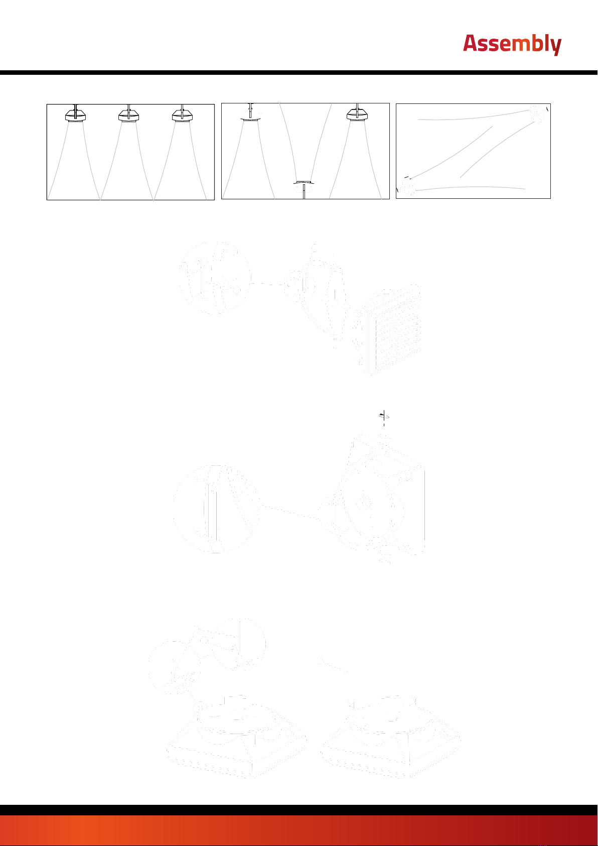
Examples of arrangement of air heating units mounted on a wall Top view
4.1 INSTALLATION WITH A BRACKET
The bracket is optional. In order to attach a bracket to the device, use crown drill bits to drill holes in the top and bottom panels of the heating unit (in places marked by 6), and insert sleeves
into the holes. Slide holder arms onto the sleeves. Insert M10 screws into the top and bottom sleeves, and fix the bracket position in relation to the heater while tightening the screws. When you
adjust the device in the right position, fit plugs onto the bracket.
The bracket unit consists of:
1. ARM (1 piece); 2. HOLDER; 3. M10 SCREW WITH A WASHER AND NUT FASTENING THE CLAMP (2 sets); 4. M10 SCREW FASTENING THE HOLDER TO THE UNIT HEATER (2
pieces); 5. PLUG (2 pieces); 6. MOUNTING SLEEVE (2 pieces)
Rotation of the device when mounted on a console
120°
4.2 INSTALLATION IN HORIZONTAL POSITION
Powrmatic WX units can be also installed in a horizontal position. To suspend the unit, special holders (1) have to be used. In order to install the holders, remove the screw (2) fixing the fan
grid, install holder (1) and screw the screw (2) in. Reapat for the remaining screws. Do not unscrew all screws at the same time!
page no. 11 of 20
WX Aquamatic Unit Heater Doc ref: M112 issue 1.5 Apr 2021
Assembly

supply
4
3
2
1
7
5
6
4.3 INSTALLATION INSTRUCTIONS AND MOUNTING DISTANCES
Installation of the heating medium supply system While installing the piping for the heating medium, secure the exchanger connection against twisting 1. The piping should not overload the
heater connections. It is possible to connect the piping with flexible connections (adjustable angle of the airflow).
WX-1-EC, WX-2-EC, WX-3-EC, WX-4-EC
return
WX-1-EC WX-2-EC, WX-3-EC, WX-4-EC
Marks L [mm]
A 247
B 517
C 308
D 610
EXAMPLE OF A HYDRAULIC SYSTEM:
1. UNIT HEATER; 2. POWER-OPERATED VALVE; 3. VENT VALVE; 4. CUT-OFF VALVE; 5. FILTER; 6. CIRCULATION PUMP; 7. BOILER
Note! Maximum operating pressure of the medium for water coils is 16 bar, tested pressure: 21 bar
Requirements of the quality medium for the water coils:
Parameter Value
Oil and grease < 1 mg/l
pH at 25oC 8 to 9
Residual water hardness [Ca2+, Mg2+]/[HCO3-] > 0.5
Oxygen < 0.1 mg/l (as low as possible)
SUPPLY
RETURN
page no. 12 of 20 WX Aquamatic Unit Heater Doc ref: M112 issue 1.0 Apr 2021
Assembly

1
WX-1-EC, WX-2-EC, WX-3-EC & WX-4-EC
AC 5 x 1,5mm2
WX-1-EC, WX-2-EC, WX-3-EC & WX-4-EC
EC
Power supply: 3 x 1,5mm2
Control:
0-10VDC: LiYCY 2x0,75 (shielded)
Heater vent/ heating medium drain
The device will be vented when you loosen the upper connecting pipe. The heating medium is drained through the lower connection pipe. When starting the device after the heating agent has
been drained, remember to vent the heater.
You need to pay special attention to secure the device against water accidentally getting into the heater casing during the agent draining process.
Connecting to the power supply
NOTICE The installation must be equipped with disconnectors at all power supply poles. Recommended safety: overload disconnector WX-1-EC – 1 A, WX-2-EC & WX-3-EC – 2 A,
WX-4-EC - 4A) and differential current safety. WX-1-EC, WX-2-EC, WX-3-EC & WX-4-EC (fan) are equipped with a terminal block accepting 7 x 2,5 mm2 electric wires. NOTICE
We recommend connecting the wires to the terminal block with pre-installed bushings.
NOTICE from serial number 18/15000 (WX-1-EC), 19/30000 (WX-2-EC/WX-3-EC/WX-4- EC) units are equipped with EC motor with protection rating IP=54 and additional terminal that
exposes +10V DC signal. The use of the referred version of the heating unit in objects with high humidity requires the placement of a connection terminal in a protective box ensuring
IP54 protection level.
WX-1-EC, WX-2-EC, WX-3-EC &
WX-4-EC
Power supply: 3 x 1,5mm2;
Control 0-10 V DC: LiYCY 2 x 0,75 mm2;
Additional output +10 V DC
Example of the nameplate, unit’s equipped with new EC motor:
Adjusting the air guides
Powrmatic WX air guides are mounted on the pivot 1, which provides smoothly change of air direction 4. In order to change position of air blade should turn it in both hands (grasping the
edges of the enclosure) to turn the blade at the same time on both pins The use of the referred version of the heating unit in objects with high humidity requires the placement of a connection
terminal in a protective box ensuring IP54 protection level.
WX-1-EC, WX-2-EC, WX-3-EC & WX-4-EC
page no. 13 of 20
WX Aquamatic Unit Heater Doc ref: M112 issue 1.5 Apr 2021
Assembly
'

5. AUTOMATICS
5.1 ELEMENTS OF AUTOMATICS
Electric connections may only be made by well-trained electricians, and according to:
Occupational health and safety regulations
Assembly instructions
Technical documentation for each of the automatic elements
NOTE Before starting the assembly process and connecting the system, familiarize yourself with the original documentation attached to the automatic devices.
MODEL
SCHEMAT
TECHNICAL DATA COMMENTS
Controller
WX-HMI
WX-HMI
● Device operation: Touch buttons
● Power supply: 230 V AC
● Maximum output current for valve or valves with actuator:
3(1)A
● Temperature measurement: -10 °C ... +99 °C ; NTC10K
● Outputs:
- 1 analog output 0-10V (8 bit, Imax = 20 mA)
- 2 relays outputs (250 VAC, AC1 500 VA dla 230 VAC)
● Communication: Modbus RTU
● Parameters of working environment: temperature:
0 - 60 °C, humidity: 10 - 90%, without condensation
● Display: blue backlight
● Dimensions: 86 mm x 86 mm x 17 mm
● Protection level: IP20
● used for control all types of units
● touch control panel
● the main on / off switch (ON / OFF)
● stepless adjustable fan speed of the EC motor
● built-in thermostat with possibility weekly programing
● continuous mode
● function of heating, cooling and ventilation
● possibility of using external temperature sensor
● RS 485 with ModbusRTU
● Suggested cross sections of electrical cables:
- L, N : 2x1 mm²
- H, C : 2x1 mm²
- AO, GND : 2x0,5 mm² LIYCY
- TS; TS : 2x0,5 mm² LIYCY
- RS 485 : 2x0,75 mm² LIYCY
page no. 14 of 20 WX Aquamatic Unit Heater Doc ref: M112 issue 1.0 Apr 2021
POTENTIOMETER WITH THERMOSTAT WX EC
● Power suply: ~230/1/50 V/ph/Hz
● Permissible load: 0,02 A for 0-10 V
● Setting range: 5…40oC
● Temperature measurement integrated in the device
● Output signal 0-10 V DC
● Protection rating: IP30
● Power connection should be done with a cable min. 2 x 0.75 mm2.
● Automation element drawings are only a visualisation of sample
products.
POTENTIOMETER WITH
THERMOSTAT WX EC
WX-C-EC (0-10V)
6. START-UP, OPERATION, MAINTENANCE
6.1 START-UP/PUTTING INTO OPERATION
● Prior to any installation or maintenance works, disconnect the device from the power supply and secure it against accidental power-up.
● Use filters in the hydraulic system. Before you connect the hydraulic lines (especially supply lines) to the device, you should clean/rinse the installation by draining a few litres out of it.
● Install vent valves at the highest point of the installation.
● Install cut-off valves directly behind the device, so it can be easily disassembled.
● Secure the device against pressure increase according to the permitted maximum pressure value of 1.6 MPa.
● Hydraulic pipes need to be free from any stresses and loads.
● Prior to the first start-up of the heater, check the hydraulic connections (vent and collector air-tightness, installed fittings).
● Prior to the first start-up of the heater, check the electric connections (connection of automatic devices, power supply, fan).
● It is suggested to use additional external current differential protection.
NOTE All connections should be made according to this technical documentation and the documentation enclosed with the automatic devices.
6.2 OPERATION AND MAINTENANCE
● Device casing does not require any maintenance.
● Heat exchanger needs to be regularly cleaned of dirt and grease. Especially before the heating season, the heat exchanger needs to be cleaned with the use of compressed air on the
side of the air guides (but the device does not need to be disassembled). Pay attention to the exchanger’s lamellas, as these are delicate.
● If lamellas bend, straighten them with a special tool.
● The fan motor does not require any maintenance. It may only require cleaning of the protective mesh, fan blades and dust and grease deposits.
● If the device is not used for a long time, disconnect the voltage supply.
● Heat exchanger does not have fire protection.
● It is recommended to periodically blow through the heat exchanger, preferably with compressed air.
● The heat exchanger can freeze (fracture) when the room temperature falls below 0°C and the heating agent temperature decreases at the same time.
● The level of air pollutants should meet the criteria allowable concentrations of pollutants in indoor air, for non-industrial areas, the level of dust concentration up to 0.3 g / m³. It is forbidden
to use device for the duration of the construction works except for the start-up of the system.
● The equipment must be operated in rooms used throughout the year, and in which there is no condensation (large fluctuations in temperature, especially below the dew point of the
moisture content). The device should not be exposed to direct UV rays.
● The device should be operated at the supply water temperature up to 130 ° C with working fan.
7. INDUSTRIAL SAFETY INSTRUCTION
Special instructions concerning safety NOTE
● Prior to any work connected with the device, the device must be disconnected from the power supply and be secured properly. Wait until the fan stops.
● Use stable assembly platforms and hoists.
● Depending on the heating agent temperature, piping, parts of the casing, heat exchanger surface can be very hot, even after the fan stops.
● There may be some sharp edges! During transport, use protective gloves, protective clothing and safety shoes.
● The health and safety instructions must be followed.
● Loads can be fastened only in places designed for it in a transport unit. While devices are lifted by an assembly unit, their edges need to be secured. Distribute the load evenly.
● The device needs to be protected against moisture and dirt and should be stored in rooms secured against atmospheric influences.
● Disposal: Take care to dispose of used materials, packaging material and spare parts in a safe way, one which is not harmful to the environment and is in accordance with local
regulations.
Automatic Devices
page no. 15of 20
WX Aquamatic Unit Heater Doc ref: M112 issue 1.5 Apr 2021
Wiring Diagrams
Q1
F1
0-1
LN PE
~230V
1
2
9
L N C H Ao
GND
TS TS
A B
Red wire
White wire
X
GND
A+ B-
12345 678
4
PE L N
+10V
Ain
Black
White
Green
Yellow
Red
Brown
Blue
Green
Yellow/
Connection of Powrmatic WX-1-EC WX-2-EC, WX-3-EC & WX-4-EC with EC motor to the WX-HMI EC controller
1-supply: 230V - 50Hz*
2-main switch, fuses*
4-WX unit
9-WX-C-EC controller
GND
A+ B-
21 345 678
Q1
F1
0-1
LN PE
~230V
1
2
4
12
PE L N
NL Ao
GND
NTC NTC
5
10
15 20
25
30
1/3
2/3
+10V
Ain
Black
White
Green
Yellow
Red
Brown
Blue
Green
Yellow/
1-supply: 230V - 50Hz*
2-main switch, fuses*
4-WX unit 12- 0-10V speed controller
* the device does not include: the main switch, fuses and feeder cable /
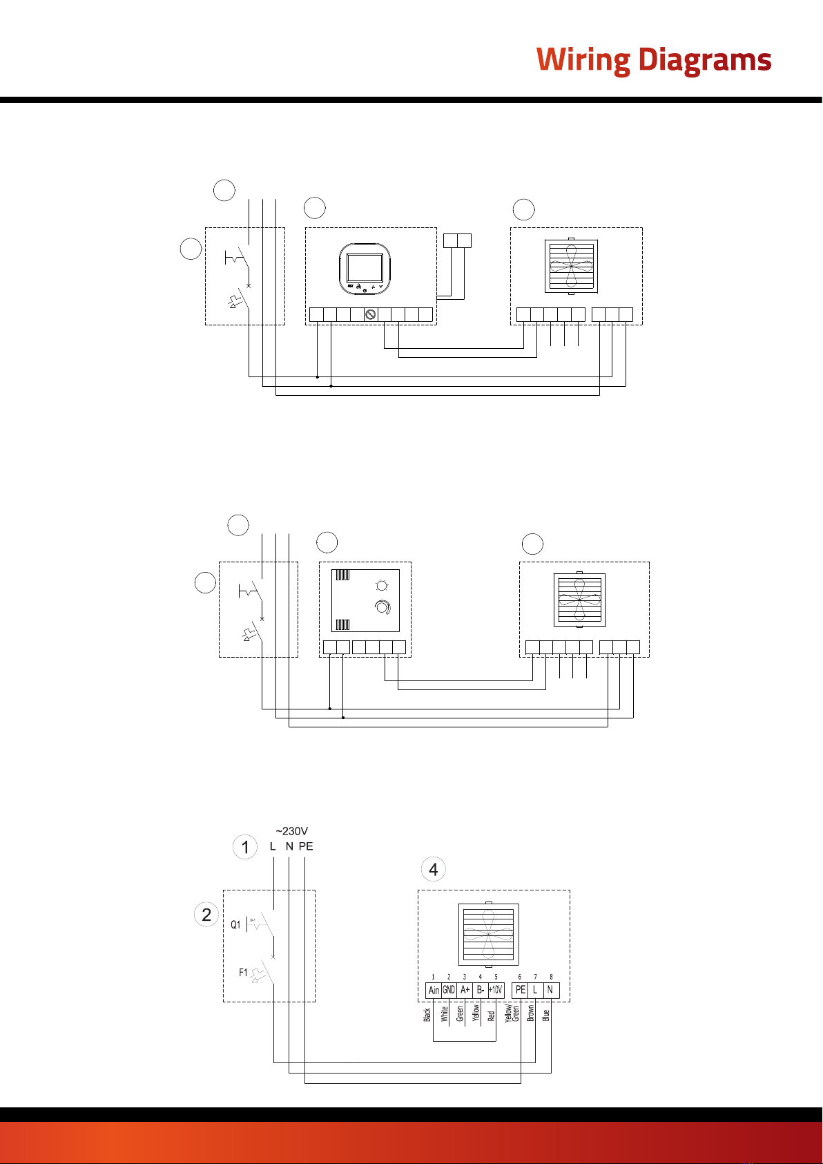
Connection without automatics
EN
1-supply: 230V - 50Hz*
2-main switch, fuses*
4-WX unit**
** Please check availability of the new motor
Electric diagram appears and concerns Powrmatic WX EC air heater, starting from serial number: WX-1-EC 18/15000, WX-2.., WX-3.., WX-4.. EC 19/30000
Connection of Powrmatic WX-1-EC WX-2-EC, WX-3-EC & WX-4-EC with EC motor to the 0-10V speed controller
●(*) Terminal X - WX-HMI - do not connect

page no. 16 of 20
9.TECHNICAL INFORMATION TO THE REGULATION (EU)
NO.327/2011 IMPLEMENTING DIRECTIVE 2009/125/EC
Model: Powrmatic WX-2-EC/WX-3-EC
Powrmatic WX-1-EC
1. 27.7% 30.6% 32.3%
2. B
3. Static
4. 40
5. VSD-No
6. 2016
7. VTS Plant Sp. z o.o., KRS 0000144190, Polska
8. 1-2-2702-0005 1-2-2701-0291 1-2-2701-0292
9. 0,105kW, 1500m³/h, 70Pa 0,27kW, 4250m³/h, 70Pa 0,38kW, 5000m³/h, 88Pa
10. 1440RPM 1370RPM 1370RPM
11. 1,0
12.
Disassembly of the machine must be carried out and/or supervised by qualified personnel with appropriate expert
knowledge.
Contact a certified waste disposal organization in your vicinity. Clarify what is expected in terms of the quality of
dismantling the machine and provision of the components.
Dismantle the machine using the general procedures commonly used in mechanical engineering.
WARNING
Machine parts can fall The machine is made up of heavy parts. These parts are liable to fall during dismantling. This can
result in death, serious injury, or material damage.
Follow the safety rules:
1. Disconnect all electrical connections.
2. Prevent reconnection.
3. Make sure that the equipment is at zero voltage.
4. Cover or isolate nearby components that are still live.
To energize the system, apply the measures in reverse order.
Components:
The machines consist for the most part of steel and various proportions of copper, aluminum and plastics and rubber-
neoprene (seat of bearings/hub, gasket). Metals are generally considered to be unlimitedly recyclable.
Sort the components for recycling according to whether they are:
Iron and steel, aluminum, non-ferrous metal, e.g. windings (the winding insulation is incinerated during copper recycling),
insulating materials, cables and wires, electronic waste (capacitor ect.), plastic parts (impeller, junction box, winding
cover ect.), rubber parts (neoprene). The same goes for cloths and cleaning substances which have been used while
working on the machine.
Dispose of the separated components according to local regulations or via a specialist disposal company.
13.
Long failure-free operation depends on keeping the product/device/fan within performance limitations described by
selection software or maintenance manual.
For proper operation, read carefully maintenance manual, with special attention on “installation”, “start-up”, and
“maintenance” chapters.
14. Inlet ring, fan grid
Powrmatic WX-4EC
Technical Directive
WX Aquamatic Unit Heater Doc ref: M112 issue 1.0 Apr 2021

page no. 17of 20
1) general efficiency (η)
2) measurement category used to determine the energy efficiency
3) efficiency category
4) efficiency coefficient in the point of optimal energy efficiency
5) whether rotational speed regulation was taken into account in the calculation of fan efficiency
6) year of manufacture
7) manufacturer’s name or trademark, business register number and place of manufacture
8) product model number
9) rated motor power consumption (kW), flow volume and pressure in the point of energy efficiency
10) rotations per minute in the point of energy efficiency
11) characteristic coefficient
12) essential information to facilitate disassembly, recycling or dispose of the product after the end of its use
13) essential information to minimize the effect on the environment and to guarantee optimum use period,
referring to disassembly, use and technical service of the fan
14) description of additional elements used in determining the energy efficiency of the fan
Model:
1. 28.5% 27.5% 28%
2. B
3. Static
4. 21
5. VSD-No
6. 2016
7. VTS Plant Sp. z o.o., KRS 0000144190, Polska
8. 1-2-2701-0304 1-2-2701-0289 1-2-2701-0290
9. 0,41kW, 2826m³/h, 145Pa 0,48kW, 4239m³/h, 124Pa 0,68kW, 6006m³/h, 128Pa
10. 1376RPM 1370RPM 1372RPM
11. 1,0
12.
Disassembly of the machine must be carried out and/or supervised by qualified personnel with appropriate expert
knowledge.
Contact a certified waste disposal organization in your vicinity. Clarify what is expected in terms of the quality of
dismantling the machine and provision of the components.
Dismantle the machine using the general procedures commonly used in mechanical engineering.
WARNING
Machine parts can fall The machine is made up of heavy parts. These parts are liable to fall during dismantling. This can
result in death, serious injury, or material damage.
Follow the safety rules:
1. Disconnect all electrical connections.
2. Prevent reconnection.
3. Make sure that the equipment is at zero voltage.
4. Cover or isolate nearby components that are still live.
To energize the system, apply the measures in reverse order.
Components:
The machines consist for the most part of steel and various proportions of copper, aluminum and plastics and rubber-
neoprene (seat of bearings/hub, gasket). Metals are generally considered to be unlimitedly recyclable.
Sort the components for recycling according to whether they are:
Iron and steel, aluminum, non-ferrous metal, e.g. windings (the winding insulation is incinerated during copper recycling),
insulating materials, cables and wires, electronic waste (capacitor ect.), plastic parts (impeller, junction box, winding
cover ect.), rubber parts (neoprene). The same goes for cloths and cleaning substances which have been used while
working on the machine.
Dispose of the separated components according to local regulations or via a specialist disposal company.
13.
Long failure-free operation depends on keeping the product/device/fan within performance limitations described by
selection software or maintenance manual.
For proper operation, read carefully maintenance manual, with special attention on “installation”, “start-up”, and
“maintenance” chapters.
14. Inlet ring, fan grid
Powrmatic WX-2-EC/WX-3-EC
Powrmatic WX-1-EC Powrmatic WX-4EC
Technical Directive
WX Aquamatic Unit Heater Doc ref: M112 issue 1.5 Apr 2021

page no. 18 of 20
10.SERVICING
10.1 PROCEDURES IN CASE OF DEFECTS
WX-1-EC/WX-2-EC/WX3-EC/WX4-EC
Problem Check points Description
Heat exchanger leaking
● assembly of the exchanger connections with two wrenches (adjustment), which
safeguards against internal twisting of the collectors,
● Check if the leakage may be associated with mechanical damage to the
exchanger,
● Vent valve or drain plug leaking,
● Heating agent parameters (pressure and temperature) – should not exceed
permitted values,
● type of heating agent (it cannot be aggressive to Al and Cu),
● Circumstances when the leakage appears (e.g. during the first, tentative
installation start-up, when the installation is filled up after the heating agent
has been drained) and outside temperature at the time of failure (risk that the
exchanger may freeze),
● Possibility of operating in aggressive conditions (e.g. high concentration of
ammonia in the air in a sewage-treatment plant),
Pay special attention that the exchanger may freeze during winter
time. 99% of registered leakages appear during installation start-up/
pressure tests. The defect can be removed by pulling back vent or
drain valve.
Fan works too loud
● check the device assembly for conformity with the instructions in operation and
maintenance manual (e.g. distance from wall/ceiling), min. 40 cm
● Device appropriately level led,
● Correctness of electric connections and qualifications of the wireman,
● Inlet current parameters (e.g. voltage, frequency),
● use of rotation controller different from ARW,
● noise at lower gears (possible controller failure?),
● Noise only at higher gears (regular situation explained by aerodynamic
characteristics of the device, if there outlet air chokes),
● type of other devices operating in the building (e.g. induced draught fans) –
intensified noise caused by simultaneous operation of many machines,
● Does the fan rub against the casing?
● Is the fan evenly screwed to the casing?
Level of operating noise of the devices is perceived subjectively. If
the device is made of plastic, it should operate quietly.It is
recommended to unscrew the clamping screws and tightening them
up again. If the fault does not disappear, you should make a
complaint.
Fan does not work
● Correctness and quality of electric connections and qualifications of the wireman,
● Is there an additional bridge between required engine terminals (diagram in the
manual) – U1 – TK (TB),
● Inlet current parameters (e.g. voltage, frequency) on the clamp block of fan
engine,
● Correctness of operation of other devices installed in the building,
● Correctness of wire connections on the engine side acc. to the manual, in
comparison to wires clamped in the engine terminal strip,
● PE conductor voltage (if present, may mean there is a break-down),
● Is N conductor correctly connected to the fan or ARW or is the connection of U2
clamps on the motor and ARW made correctly?
Electrical connection need to be done strictly according to the
drawings in the manual. If there is no bridge between U1 and
TK(TB) clamps, the motor lacks thermal protection and may break
– burn.
● damage or installation of controller different from ARW, It is recommended to check the device/ speed controller by
connecting the heater directly to power supply.
Damaged casing ● Circumstances when it was damaged – notes on the bill of ladings, stock issue
confirmation, condition of the box,
If the casing is damaged, make photos of the box and device, and
photos confirming that the device serial number on the device
and on the box are the same. If the device was damaged during
transport, it is necessary to write down an appropriate statement by
the driver, who delivered the damaged device.
ARW – rotation controller
does not work/ it is burned
● Correctness – quality of electric connections (wires accurately positioned
in electric clamps, cross-section and the material wires are made of) and
qualifications of the wireman,
● Only 1 controller connected to 1 device,
● Inlet current parameters (e.g. voltage, frequency),
● Correctness of operation after connecting “in short” (skipping ARW, i.e.
connections L and TB, N and U2, PE and PE) to the power network,
● Check if the user did not damage the knob, e.g. rotating it around
For the TRANSRATE controller, the following must also be
checked:
● circuit breaker,
● correctness of connection to the SCR10 controller,
● use of shielded conductors,
● control conductors, which should be located away from the
working conductors
Actuator does not open
the valve
● Correctness of electric connections and qualifications of the wireman,
● Correctness of the thermostat operation (characteristic tick sound during change-
over),
● Inlet current parameters (e.g. voltage),
The most important is to check whether the actuator responded
to the electric impulse within 11s. If the motor is damaged, you
need to make a complain and switch actuator operation to manual
(MAN), which mechanically opens the valve.
Programmable thermostat
does not send any signals
to the actuator/ controls
the operation of the
heating system wrongly
● Correctness of electric connections and qualifications of the wireman,
● Correctness of the thermostat operation (characteristic tick sound during switch-
over),
● Connecting a few motor of the devices directly to the thermostat
(permitted only if contactor is used!),
● Inlet current parameters (e.g. voltage),
● Programming method exactly the same as in the manual
● When was the last time the sensor was calibrated?
RDE thermostat is powered by batteries, that need to be replaced
(every 2 years). Also, the sensor needs to be periodically calibrated
– detailed information can be found on: www.vtsgroup.com
Complaint is unjustified, if the RDE thermostat was directly
connected to the motor, without a contactor. If the sensor incorrectly
measures the temperature, it should be calibrated (instructions in
the catalogue).
Servicing
WX Aquamatic Unit Heater Doc ref: M112 issue 1.0 Apr 2021

page no. 19of 20
The company submitting the notification:
The company that installed the equipment:
Date of notification:
Type of device:
Factory number*:
Date of purchase:
Date of installation:
Place of installation:
Detailed description of defect:
Contact person:
Name and surname:
Telephone:
E-mail:
Complaint Form
* This field must be filled, if the complaint notification refers to the following equipment: WX-1-EC/WX-2-EC/WX-3-EC/WX-4-EC
Servicing
WX Aquamatic Unit Heater Doc ref: M112 issue 1.5 Apr 2021
WX Aquamatic Unit Heater Doc ref: M312 issue 1.0 Apr 2021

page no. 4 of 20 WX Aquamatic Unit Heater Doc ref: M312 issue 1.0 Apr 2021
Stamm International Corporation
PO Box 1929
Fort Lee, NJ 07024
Tel: 201-947-1700
Fax: 201-947-9662
E-mail: stamminc@pobox.com
Stamm International HQ
www.powrmatic.co.uk
www.powrmatic.co.uk
®
Powrmatic Limited
Hort Bridge, Ilminster
Somerset
TA19 9PS
tel: +44 (0) 1460 53535
fax: +44 (0) 1460 52341
e-mail: [email protected]
web: www.powrmatic.co.uk
Powrmatic Ireland
45 Broomhill Close
Tallaght
Dublin 24
tel: +353 (0) 1452 1533
fax: +353 (0) 1452 1764
e-mail: [email protected]
web: www.powrmatic.ie
Getting In Touch
Powrmatic pursues a policy of continues improvement in both design and performance of its products and therefore reserves the right to change, amend or
vary specifications without notice. Whilst the details contained herein are believed to be correct they do not form the basis of any contract and interested
parties should contact the Company to confirm whether any material alterations have been made since publication of this brochure.
EURO-AIR
QUALITY
ICOM
Energy Association
More information is available from our website by scanning the following QR code.
Stamm International Corporation
PO Box 1929
Fort Lee, NJ 07024
Tel: 201-947-1700
Fax: 201-947-9662
E-mail: stamminc@pobox.com
Stamm International HQ
www.powrmatic.co.uk
www.powrmatic.co.uk
®
Powrmatic Limited
Hort Bridge, Ilminster
Somerset
TA19 9PS
tel: +44 (0) 1460 53535
fax: +44 (0) 1460 52341
e-mail: inf[email protected]o.uk
web: www.powrmatic.co.uk
Powrmatic Ireland
45 Broomhill Close
Tallaght
Dublin 24
tel: +353 (0) 1452 1533
fax: +353 (0) 1452 1764
e-mail: inf[email protected]
web: www.powrmatic.ie
Getting In Touch
Powrmatic pursues a policy of continues improvement in both design and performance of its products and therefore reserves the right to change, amend or
vary specifications without notice. Whilst the details contained herein are believed to be correct they do not form the basis of any contract and interested
parties should contact the Company to confirm whether any material alterations have been made since publication of this brochure.
EURO-AIR
QUALITY
ICOM
Energy Association
This manual suits for next models
4
Popular Ventilation Hood manuals by other brands

FALMEC
FALMEC Design Kristal Isola 90 Inox Instruction booklet

Amica
Amica OTP6233W operating instructions

Klarstein
Klarstein 10004851 manual

TESY
TESY CH34201T60G Instructions for use and maintenance

ELICA
ELICA SPACE EDS DIGITAL R WH A/78 Instruction on mounting and use

privileg
privileg SY-103E6S-E11-C29-L12-900 user manual


