AJUSTES DE FÁBRICA
de fábrica.
1. Con el portón inmóvil, cierre el jumper
JPROG, el LED SN1 empieza a parpadear 2x
mientras no se pulsa el botón CMD;
2. Pulse CMD 1x y después GRV para entrar
en la función
fábrica o CMD para cancelar y volver.
al menu de funciones;
4. Quite el jumper JPROG;
LED SN1:
- Parpadea 1x cada vez que reconoce
botón pulsado
LED SN2:
- Parpadea 1x;
TIEMPO AUTOMÁTICO/
SEMIAUTOMÁTICO
Después de finalizar el ciclo de apertura, el
portón espera el tiempo de pausa configu-
modo ‘automático’ está habilitado.
Los LEDs SN1 y SN2 parpadean a cada
1 segundo indicando decremento del tiempo.
Cuando el tiempo de pausa es configurado
comando siguiente para cerrar.
1. Con el portón inmóvil, cierre el jumper
JPROG, el LED SN1 empieza a parpadear 2x
mientras no se pulsa el botón CMD;
2. Pulse CMD 2x y después GRV para
para entrar en la función;
3. Pulse GRV para incrementar el tiempo de
espera en modo automático o CMD para
disminuir el tiempo;
queda en la función semiautomática;
5. Intervalos de 10 segundos y tiempo máximo
de 120 segundos;
Valores:
0 = Automático deshabilitado;
1= 10 segundos de pausa;
2 = 20 segundos de pausa;
…
12= 120 segundos de pausa;
LED SN1:
- Parpadea 1x cuando reconoce botón
pulsado;
- Parpadea 1x por 10 segundos del tiempo, por
ejemplo: 30 seg. de pausa, LED parpadea 3x;
- Parpadea continuamente - modo automático
deshabilitado;
Permanece encendido en el tiempo máximo.
LED SN2:
-Parpadea 2x;
P06105 - Rev. 3
IMPORTANTE
Antes de utilizar este equipo, lea,
comprenda y siga todas las
instrucciones contenidas en este
CENTRAL
POP PROG
MANUAL
TÉCNICO
TIEMPO DE LUZ DE CORTESÍA /
RETARDO
PRINCIPALES CARACTERÍSTICAS
- Fin de Carrera Analógico;
- Módulo Receptor 433.92MHz;
- Número máximo de controles remotos: 50;
- Ajuste del embrague electrónico (fuerza);
- Memorización automática de recorrido A/C;
- Entradas Para:
Fotocélula, utilizar alimentación externa;
Botonera;
- Salidas para módulos:
Electrocerradura;
Luz de Cortesía;
- Ajuste de freno;
- Ajuste de rampa;
- Ajuste de torque de rampa;
- Tiempo de retardo para apertura con semáforo;
- Configuración via PROG PPA.
Configuración estándar de fábrica
Tiempo de recorrido 2 Minutos, tiempo
máximo
Tiempo automático Deshabilitado
Tiempo de Luz de
Cortesía Semáforo (0 segundo)
Freno Nivel 1
Fuerza Nivel 8, máximo
Rampa de Apertura Deshabilitado
Rampa de Cierre Deshabilitado
Torque Rampa de
Apertura Nivel 6
Torque Rampa de
Cierre Nivel 6
TABLA ESTÁNDAR DE FÁBRICA
1 - Estándar de fábrica Abrir Función 1xCMD Entrar Función 1xGRV 1xGRV Cancelar 1xCMD
2 - Tiempo Automático Abrir Función 2xCMD Entrar Función 1xGRV Incrementar 1xGRV Disminuir 1xCMD
3 - Borrar TX Abrir Función 3xCMD Entrar Función 1xGRV 1xGRV Cancelar 1xCMD
Abrir Función 4xCMD Entrar Función 1xGRV Incrementar 1xGRV Diminuir 1xCMD
5 - No utilizado
6 - Freno Abrir Función 6xCMD Entrar Función 1xGRV Incrementar 1xGRV Disminuir 1xCMD
7 - Fuerza Abrir Función 7xCMD Entrar Función 1xGRV Incrementar 1xGRV Disminuir 1xCMD
8 - Rampa de Apertura Abrir Función 8xCMD Entrar Función 1xGRV Disminuir Distáncia 1xCMD
9 - Rampa de Cierre Abrir Función 9xCMD Aumentar Distáncia 1xGRV Disminuir Distáncia 1xCMD
TABLA DE FUNCIONES
Entrar Función 1xGRV
Aumentar Distáncia 1xGRV
10 - Torque Rampa de
Apertura
Abrir Función 10xCMD Entrar Función 1xGRV Disminuir Torque
1xCMD
Incrementar Torque
1xGRV
11 - Torque Rampa de
Cierre
Abrir Función 11xCMD Entrar Función 1xGRV Disminuir Torque
1xCMD
Incrementar Torque
1xGRV
4 - Tiempo Luz de
Cortesía / Retardo
Configuración del tiempo para apagar el
módulo relé de la luz de cortesía cuando
el portón llegue al final de carrera de
cierre o el tiempo de espera para el
portón empiezar a abrir después del
accionamiento del módulo relé conecta-
do a la salida "LUZ" (semáforo).
Para Tiempo de Luz de Cortesía:
El ajuste tiene niveles de 0 a 7, tiempo
máximo de 4 minutos.
Operación: La luz de cortesía quedará
encendida siempre que el portón esté en
movimiento o esté abierto a espera de
un nuevo comando, y se apagará
cuando el portón se cierre por completo
y después de finalizar el tiempo progra-
mado.
Para Retardo en la Apertura con Semá-
foro encendido:
El ajuste tiene niveles de 8 a 12, tiempo
máximo de 16 segundos.
Operación: Cuando el portón está
cerrado totalmente y recibir un comando
para el ciclo de apertura, el semáforo
será accionado y quedará encendido por
el tiempo programado y después el
motor será accionado. El semáforo se
apagará al final del ciclo de cierre del
portón, o cuando reciba un nuevo
comando por el controle remoto duran-
te la temporización del retardo.
1. Con el portón inmóvil, cierre el jumper
JPROG, el LED SN1 parpadea 2x mientras
no se presione el botón CMD;
2. Pulse CMD 4x y después GRV para
entrar en la función;
BORRAR CONTROLES
REMOTOS
Borra la memoria para añadir nuevos controles
remotos.
1. Con el portón inmóvil, cierre el jumper
JPROG, el LED SN1 empieza a parpadear
2x mientras no se pulsa el botón CMD;
2. Pulse CMD 3x y después GRV para
entrar en la función;
3. Pulse GRV para borrar los controles
remotos o CMD para cancelar y volver al
menú de funciones;
4. Quite el jumper PROG;
LED SN1:
- Parpadea 1x cuando reconoce botón
pulsado;
- Parpadea 10x rápidamente confirmando
la exclusión de los controles remotos;
LED SN2:
- Parpadea 3x;
manual.
Restaurar la configuración del valor estándar
3. Pulse GRV para confirmar los ajustes de
rado y cierra automáticamente, cuando el
como deshabilitado, el portón espera el
4. Cerar (resetar) el tiempo - el portón se
6. Quite el jumper JPROG;
COMODIDAD Y SEGURIDAD
BORRANDO RECORRIDO
Volver el tiempo de recorrido a 1 minuto.
1. El portón debe estar inmóvil;
2. Con el jumper JPROG abierto, pulse el botón
GRV+ y lo mantenga pulsado por 3segundos
3. LEDs SN1 y SN2 parpadearán para confirmar la
- Inicio y salida de la programación: LED
SN1 (rojo) parpadea 1x, despacio;
- Último Comando - Apertura: LED SN2
(verde) parpadea 3 veces, rápidamente
- Último Comando - Cierre: LED SN1
parpadea 4 veces, rápidamente
- Fotocélula accionada: LED SN1
permanece encendido.
3. Pulse GRV para incrementar el tiempo de
apagado de la luz de cortesía o CMD para
decrementar;
4. Intervalos de 30 segundos para luz de cortesía;
5. Tiempo Máximo para luz de cortesía es de 4
minutos;
6. Tiempos de configuración de retardo: Desde
3 hasta 16 segundos (Intervalos de 3 segundos)
7. Quite el jumper JPROG.
Niveles
0 - 0 segundos (semáforo)
1 - 30 segundos
2 - 60 segundos
3 - 90 segundos
4 - 120 segundos
5 - 150 segundos
6 - 180 segundos
7 - 240 segundos
Tiempo de retardo, niveles:
8 - 3 segundos
9 - 7 segundos
10 - 10 segundos
11 - 13 segundos
12 - 16 segundos (máximo)
LED SN1:
- Parpadea 1x cuando reconoce botón pulsado;
- Parpadea continuamente para tiempo mínimo,
nivel 0;
- Permanece encendido para tiempo máximo;
- Parpadea 1x a cada nivel, por ejemplo: nivel 6,
LED parpadea 6x.
LED SN2:
-Parpadea 4x;
FRENO
Cuando hay comando para apagar el motor, el
freno será accionado con posibilidad de ajuste
de sensibilidad.
1. Con el portón inmóvil, cierre el jumper
JPROG, el LED SN1 empieza a parpadear 2x
mientras no presiona el botón CMD;
2. Pulse CMD 6x y después GRV para entrar en
la función;
3. Pulse GRV para incrementar la sensibilidad
del freno;
4. Pulse CMD para disminuir la sensibilidad del
freno;
5. En el valor mínimo el freno es deshabilitado,
con la posibilidad de ajuste de 10 niveles de
sensibilidad.
LED SN1:
- Parpadea continuamente para ajuste Mínimo,
freno desahbilitado;
- Parpadea 1x para cada incremento de sensibi-
lidad, con valor máximo igual a 10;
LED SN1:
- Parpadea 1x cuando reconoce botón pulsado;
- Parpadea continuamente para ajuste mínimo,
deshabilitado;
- Parpadea 1x para cada incremento de
sensibilidad, con un valor máximo igual a 12;
- Permanece encendido en el valor máximo.
LED SN2:
- Parpadea 8x, para apertura;
- Parpadea 9x, para cierre.
TORQUE EN RAMPA
La central disminuirá el torque de operación
tan pronto llegue al límite de fin de carrera
programado. El torque es programado por
separado para apertura y cierre.
1. Con el portón inmóvil, cierre el jumper
JPROG; el LED SN1 empieza a parpadear 2x
mientras no se presione el botón CMD.
2. Pulse CMD 10x para torque rampa de
apertura y 11x para torque rampa de cierre y
luego GRV para entrar en la función;
3. Pulse GRV para aumentar el torque;
4. Pulse CMD para disminuir el torque;
LED SN1:
- Parpadea 1x cuando reconoce botón
pulsado;
- Parpadea continuamente para un ajuste
mínimo;
- Parpadea 1x para cada incremento de
sensibilidad, con un valor máximo igual a 8;
- Permanece encendida en el valor máximo.
LED SN2:
- Parpadea 10x (Apertura);
- Parpadea 11x (Cierre);
AÑADIR CONTROLES REMO-
TOS
Controles Remotos estándar PPA.
1. Con el portón inmóvil, cierre el jumper
JPROG, LED SN1 empieza a parpadear 2x;
2. Pulse el botón del control remoto, el LED
SN2 empiezará a parpadear cada vez que
recibir un código válido;
3. Pulse y suelte el botón GRV;
4. Suelte el botón del control remoto;
5. Control remoto añadido con éxito - LED
SN1 y SN2 parpadean;
6. Botón registrado - LED SN1 parpadea 2x;
7. Memoria llena - LED SN1 parpadea 3x;
8. Para añadir un nuevo botón del control
remoto, vuelva al paso 3;
9. Quite el jumper JPROG para finalizar;
INDICACIÓN EXTRA EN
LOS LEDs
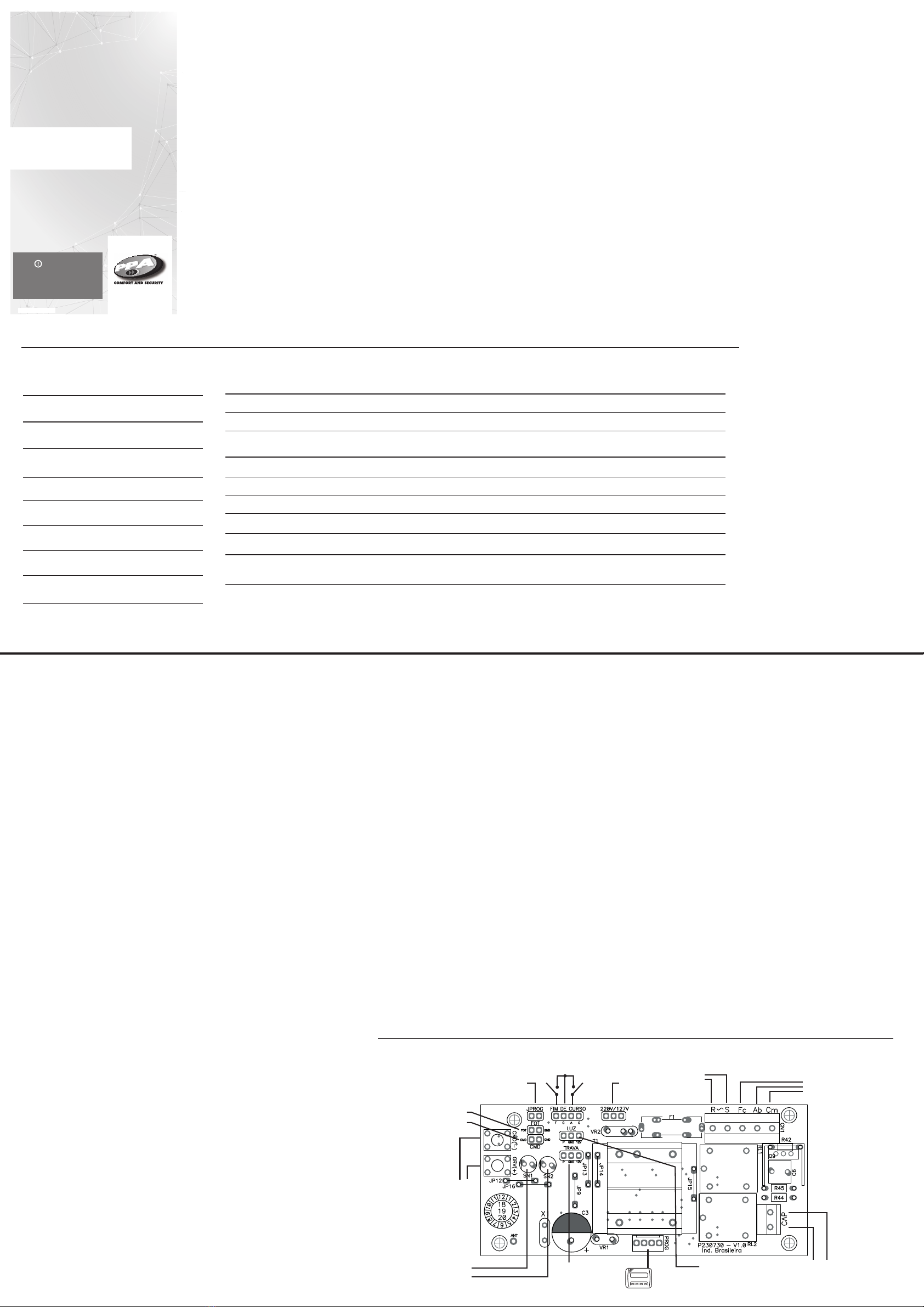
ESQUEMA ELÉCTRICO
FUERZA (EMBRAGUE ELEC-
TRÓNICO)
Ajusta la fuerza de operación del motor.
Para que el uso de este dispositivo sensor
de seguridad sea eficaz, haga lo siguiente:
- - Después de la correcta instalación del
automatizador en el portón, regule el embra-
gue electrónico; de manera que la fuerza sea la
mínima necesaria para desplazar la hoja del
portón en todo su recorrido, en la apertura y
cierre;
- Al final del ajuste, pruebe la función, bloque-
ando el movimiento del portón, poniendo un
objeto rígido en el recorrido del portón.
1. Con el portón inmóvil, cierre el jumper
JPROG; el LED SN1 empieza a parpadear
2x mientras no se presione el botón CMD;
2. Pulse CMD 7x y luego GRV para entrar
en la función;
3. Pulse GRV para incrementar la fuerza o
CMD para decrementar;
4. Nivel máximo de fuerza: 8;
5. Quite el jumper JPROG;
LED SN1:
-Parpadea 1x cuando reconoce un botón
pulsado;
-Parpadea continuamente para fuerza
mínima, nivel 0;
-Queda encendido p/ máxima fuerza, nivel 7.
- Parpadea 1x según el nivel seleccionado,
por ejemplo: nivel 3, LED parpadea 3x.
LED SN2:
-Parpadea 7x;
AJUSTE DE RAMPA DE
APERTURA Y CIERRE
La rampa es la distancia restante para
alcanzar el stop mecánico.
La central quedará monitoreando continu-
amente la posición del portón y cuando
alcance este límite la velocidad de operaci-
ón disminuye, llegando al stop mecánico
suavemente.
1. Con el portón inmóvil, cierre el jumper
JPROG; el LED SN1 empieza a parpadear
2x mientras no se presione el botón CMD;
2. Pulse CMD 8x para rampa de apertura, o
presione CMD 9x para rampa de cierre y
después GRV para entrar en la función;
3. Pulse GRV para alejar el límite al stop
mecánico, aumentando la distancia;
4. Pulse CMD para disminuir la distancia
hacia el final de carrera;
5. En el valor mínimo la rampa está
deshabilitada, con posibilidad de ajuste de
12 niveles de sensibilidad.
MOTOR DE
INDUCCIÓN
MONOFÁSICO
RED
ELÉCTRICA
(127/220V)
JUMPER
SELECTOR
DE VOLTAJE
JUMPER DE
PROGRAMACIÓN
LEDS DE
INDICACIÓN
MÓDULO DE RELÉ DE LUZ
DE CORTESÍA (OPCIONAL) CONDENSADOR DE
ARRANQUE
MÓDULO DE RELÉ DE
ELECTROCERRADURA
(OPCIONAL) PROG PPA
FOTOCÉLULA
BOTONERA
BOTONES DE
CONFIGURACIÓN
FCC FCA
operación.
P06581 - Rev.3