P+S Technik WEISSCAM HS-2 User manual

User Manual
ENGLISH
Before operating this product, please read the
instruction carefully and save this manual for future
use. Subject to technical change without any prior
notice.
Art. Nr. 25801 | v0908

2
Manufacturer Information
The manufacturer of this product is
P+S Technik GmbH
Siemensstraße 12
85521 Ottobrunn / Munich
Germany
Phone +49-(0)89-45 09 82-30
Fax +49-(0)89-45 09 82-40
Email weisscam@pstechnik.de
Web www.pstechnik.de
Please find worldwide authorised representation and dealer on our website www.pstechnik.de in
the rental section or send an e-mail to weisscam@pstechnik.de requesting the contact details.
Concerning any service and warranty requests, please contact your local distributor
or P+S Technik directly by email at helpdesk@pstechnik.de
3
Safety Notes
CAUTION
RISK OF ELECTRIC SHOCK
DO NOT OPEN
CAUTION: TO REDUCE THE RISK OF ELECTRIC SHOCK,
DO NOT REMOVE COVER (OR BACK).
NO USER SERVICEABLE PARTS INSIDE.
REFER TO SERVICING TO QUALIFIED SERVICE PERSONNEL.
Warning:
To reduce the risk of fire or shock hazard, do not expose this equipment to rain of moisture.
To reduce the risk of fire or shock hazard, keep this equipment away from all liquids.
Use and store only in locations which are not exposed to the risk of dripping or splashing
liquids, and do not place any liquid containers on top of the equipment.
Caution:
To reduce the risk of fire or shock hazard and annoying interference, use the recommended
accessories only.
FCC Note:
This equipment has been tested and found to comply with the limits for a class A digital device,
pursuant to Part 15 of the FCC Rules. These limits are designed to provide reasonable protection
against harmful interference when the equipment is operated in a commercial environment. This
equipment generates, uses, and can radiate radio frequency energy, and if not installed and used in
accordance with the instruction manual, may cause harmful interference to radio communications.
Operation of this equipment in a residental area is likely to cause harmful interference in which case
the user will be required to correct the interference at his own expense.
Warning:
To assure continued FCC emission limit compliance, the user must use only shielded interface
cables when connecting to external units. Also, any unauthorized changes or modifications to this
equipment could void the user´s authority to operate it.
The lightning flash with arrowhead symbol, within an equilateral triangle, is intended to alert
the user to the presence of uninsulated "dangerous voltage" within the product´s enclosure
that may be of sufficient magnitude to constitute a risk of electric shock to persons.
The exclamation point within an equilateral triangle is intended to alert the user to the
presence of important operating and maintenance (service) instructions in the litera-
ture accompanying the appliance.
To prevent damages to the device, do not expose it to extreme moisture, rain, heat or dust.
Do not open the device yourself. Have repairs carried out by qualified technicians in authorised
specialist companies only.
Do not touch the low-pass filter in front of the sensor.
–
–
–

4
To ensure reliable, proper operation, it is required that you familiarise yourself with this operat-
ing manual.
Only use compatible power supply units/batteries that conform with the voltage range of
the device.
Any auxiliary equipment must not exceed the maximum permitted power.
Ensure safe transport in the cases provided for this purpose.
Keep all ventilation openings unobstructed to guarantee continuous cooling of the components.
Disconnect the device from the power supply prior to care and maintenance tasks.
Avoid direct light exposure of the sensor and do not touch the sensor.
Do not use the camera without the lens or protective cap.
Clean optical surfaces using optical cleaning agents only.
–
–
–
–
–
–
–
–
–

5
Content
Manufacturer Information ����������������������������������� 2
Safety Notes ������������������������������������������� 3
1. Overview �������������������������������������������� 7
1.1 Features �������������������������������������������� 7
1.2 Dimensions������������������������������������������ 8
1.3 Connections ���������������������������������������� 13
2. Functional description����������������������������������� 17
2.1 Setup �������������������������������������������� 17
2.2 Operation ����������������������������������������� 21
2.3 Updating the Firmware ��������������������������������� 40
2.4 Miscellaneous��������������������������������������� 42
3. Troubleshooting �������������������������������������� 49
4. Technical Specifications ��������������������������������� 53
5. Addresses and Contacts ��������������������������������� 57

6

7
11
Overview
1. Overview
1.1 Features
The WEISSCAM HS-2 is the newest, uncompressed digital Highspeed Camera for framerates up to
4.000fps. It is developed as a Stand-alone camera aiming especially the needs of cinematographers.
Coming with an easy workflow, two Streams (RAW + HD) via HD SDI, and cinema-style images, it
is designed to offer you the freedom of shooting either in HD or RAW mode.
The WEISSCAM HS-2 has a full Format Super35 CMOS Sensor with a global shutter. By using
the Interchangeable Mount System (IMS) from P+S TECHNIK you can attach nearly every lenses
on the camera (PL Mount, Nikon F-Mount, Panavision Mount, etc.) and also change the Mount
within a few seconds.
The output of the WEISSCAM HS-2 offers two Streams at the same time and uses the HD SDI
interface for both signals. With the WEISSCAM "RAW IN HD SDI" mapping, you are able to trans-
port the RAW files via the worldwide standard and fast HD SDI single and dual link interface.
The HD stream offers YCbCr in 4:2:2. You can choose between linear standard curves like ITU-R
709 or log curve for a higher contrast range within the HD SDI image.
The RAW stream is a 12Bit uncompressed WEISSCAM RAW file and gives you the freedom to
debayer in post production.
In conjunction with the WEISSCAM DIGIMAG DM-2, you are able to record both formats via HD SDI:
YCbCr and RAW.
An intelligent master/ slave DC/DC power management, saves the camera from any short circuit
and makes it needless to turn off the camera for a battery change.
A lot of mounting possibilities allows you to connect additional accessories like onboard monitor,
lens control system, etc. and power them by the several outputs of the DC/DC board.
The very fast boot up time allows you to be ready to shoot in less than 30 seconds.
8
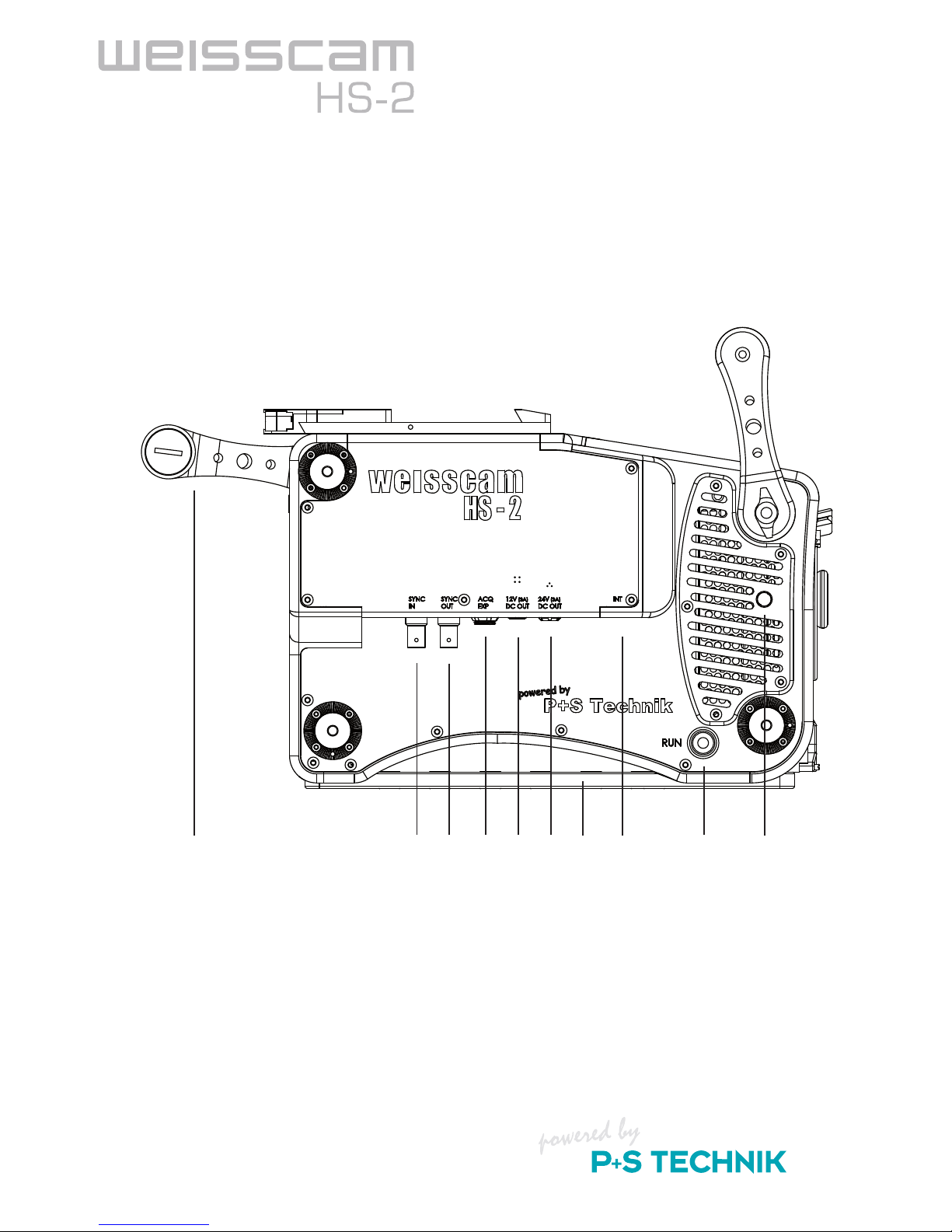
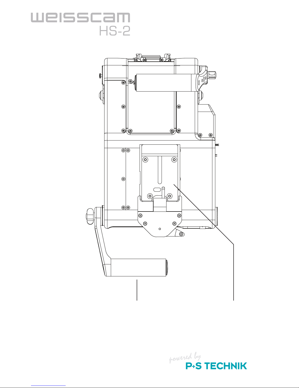
1.2 Dimensions
Dimensions of the external housing:
Height: 210.4 mm Length: 315.9 mm Width: 200.7 mm
Weight of camera body only: Approx. 6,8 kg
10 1 2 3 4 5 9 6 7 8
SYNC IN
SYNC OUT
ACQ EXP
12V/3A DC OUT
24V/3A DC OUT
INT - Debayerboard Firmware update
1.
2.
3.
4.
5.
6.
EXT. RUN trigger
Tape hook
Adapter plate
Handles
7.
8.
9.
10.

9
11
Overview
1 2 3 4 2 5 6
Tape hook
Ventilation exhaust air
EXT. RUN trigger
1.
2.
3.
Adapter plate
Rosettes
Handles
4.
5.
6.
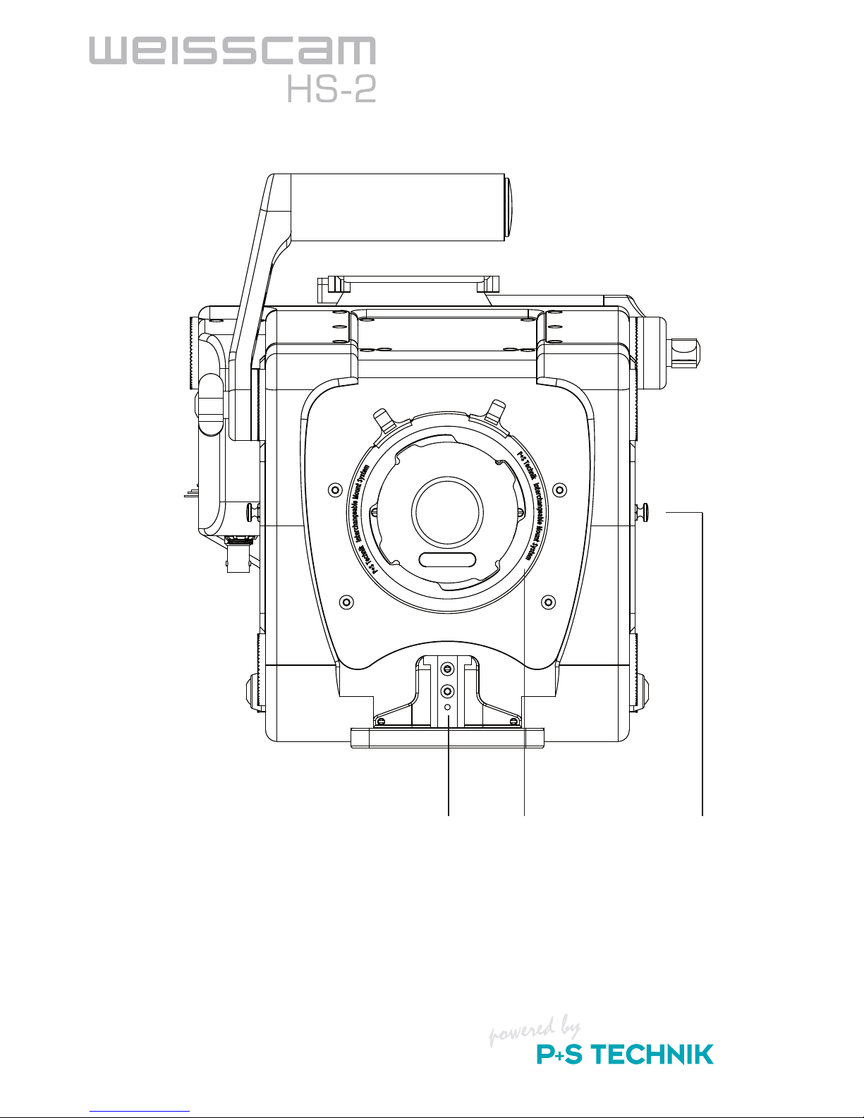
10
1 2 3
Accessory shoe for ARRI Lightweight
Support
1. IMS Interchangeable Mount System
Tape hook
2.
3.
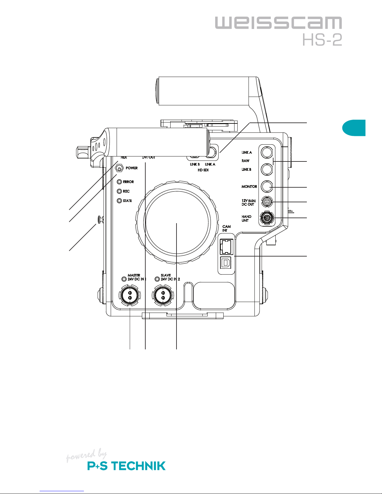
11
11
Overview
7.
8.
9.
10.
11.
12.
4 5 6
1.
2.
3.
HEX switch
Power switch
Tape hook
MASTER / SLAVE 24V DC IN
DVI OUT
Ventilation, air supply
1.
2.
3.
4.
5.
6.
HD-SDI Link A & Link B
RAW Link A & Link B
Monitor OUT
12V (0.5A) DC OUT
Hand Unit
CamINT (Ethernet / USB B)
7.
8.
9.
10.
11.
12.
12
1 2
Handle1. Mounting plate for
WEISSCAM DigiMag DM-2
2.
13
11
Overview
1.3 Connections
Sync in/out: These ports enable you to synchronise multiple WEISSCAM HS-2 cameras
with pixel accuracy. The master camera (sync generator) is initialised via
short-circuiting at the sync in and outputs the sync signal at the sync out.
Thus, multiple cameras can be connected in series and all cameras are syn-
chronised via the master camera.
ACQ EXP: You can connect devices (accessories) for controlling start/stop signals and
changes of speed here. To do so, the camera must be put into recording
mode via another operating unit (computer or WEISSCAM Hand Unit HU-2).
(will be implemented)
12V / 0.5A DC out: For supplying power to the viewfinder. Lemo 4-pin socket.
Only devices with a maximum power of 6 watts may be connected here.
12V / 3A DC out: For supplying power to auxiliary equipment. Lemo 4-pin socket.
Only devices with a maximum power of 36 watts may be connected here.
24V / 3A DC out: For supplying power to auxiliary equipment. Fischer 3-pin socket.
Only devices with a maximum power of 72 watts may be connected here.
INT: Firmware updates can be loaded onto the internal Debayerbox via this USB-B
interface. It is also possible to control the internal Debayerbox via software.
Power switch: Toggle switch for switching on the camera.
Downward: Switching on, camera boots up
Upward: Switching off
After the camera has booted up correctly, the green "STATUS" LED is illumi-
nated constantly and the camera is ready for operation.
HEX: Rotary switch for selecting the 16 presets of the internal Debayerboard
(e.g. colour temp, cine curves, focus filter etc.).
This switch directly impacts the HD-SDI output signal.
DVI-OUT: Analogue DVI signal with SVGA 800x600 pixels, for viewfinder
(see accessories) or monitor (preview).
HD-SDI Link A;B: The WEISSCAM HS-2 is equipped with an internal debayer board, which
is used to debayer the RAW data in the 1080p or 720p (RAW) signal of the
sensor in real time and convert into a YCbCr 4:2:2 single link or YCbCr
4:2:2 dual stream signal.
For resolutions outside of the HD standard (e.g. 2K with 2048x1536),

14
you can only operate the camera in RAW mode.
RAW Link A;B: In RAW mode, the pure RAW data of the sensor are output via HD-SDI.
Here, HD-SDI serves strictly as the transport stream.
Monitor: Currently same signal as RAW LINK A.
Hand Unit: The WEISSCAM Hand Unit HU-2 is connected to this connector.
CamINT: GigE interface - The camera can be connected to a PC System using a con-
ventional Ethernet cable via the gigabit Ethernet interface. All functions of the
camera can thus be controlled via the WEISSCAM software (basic version).
USB - B interface, port for loading camera firmware updates as well as
controlling the camera over the WEISSCAM software.
MASTER/SLAVE: Intelligent master/slave 24V DC IN changeover circuit. It is intended to elimi-
nate any potential image loss due to an unexpected power failure.
–
Connect the main power source (power supply unit) to the DC IN 1 (master).
– Connect the spare battery to the DC IN 2 (slave).
If an unexpected voltage drop should occur at the master input, the device
immediately switches to the slave input without impacting camera function.
Once there is sufficient voltage at the master input again, the camera auto-
matically switches back to it.
IMS: The Interchangeable Mount System by P+S TECHNIK makes changing cam-
era mounts fast and uncomplicated.
When the camera mounts are changed, the flange back is offset by the mounts.
The following mounts are available from P+S TECHNIK:
PL-Mount
Panavision-Mount
Professional F-Mount
Nikon F-Mount
Canon EF-Mount
Canon FD-Mount
BNC R-Mount
Contax-Mount
Leica M-Mount
–
–
–
–
–
–
–
–
–
15
2
Functional Description
2. Functional description
2.1 Setup
2.1.1 Camera Support
Attaching using a bridge plate:
Compatible bridge plates are the ARRI BP-5 and BP-8 for Standard35 format.
Position the bridge plate with the screwed-on adapter plate on the bottom of the camera.
Allow the parallel pin to engage into the bore provided and fasten the screw so that it is securely
tightened. You can now slide the bridge plate onto the dovetail plate.
Attaching using ARRI or Chrosziel quicklock plates:
The camera is equipped with an integrated interface for the quicklock plates as used with HD
cameras. interface connects well with ARRI and Chrosziel quicklock plates. The Sony VCT-14 is
currently not supported.
The interface is located underneath the bridge plate adapter plate screwed onto the bottom of the
camera. Unscrew the adapter plate. Then position the camera on the guide rails of the quicklock
plate and slide it forwards until the safety lever can be engaged. Check that the camera is firmly
and securely attached.
Tripod head:
Due to the weight of the camera, use tripod heads with a diameter of 150 mm only.
Examples of suitable tripod heads:
ARRIHEAD (C)
ARRI Fluid Heads
Sachtler 150H
O´Connor 2575
Attaching handles / accessories:
Both camera sides have rosettes, which can be used to attach the handle system provided as well
as additional accessories. ¼ inch screws are used for fastening the devices.
–
–
–
–
16
2.1.2 Wiring
Power supply unit / battery
Connect the power supply unit provided to the "MASTER DC IN 1" of the camera via the 4-pin
XLR / 2-pin Fischer cable.
To protect against image loss during a power failure or due to pulling the power plug accidentally,
a charged battery should be connected to the "SLAVE DC IN 2".
This battery that is connected to the "SLAVE DC IN 2" will neither be discharged nor run empty
while the camera is properly operated via "MASTER DC IN 1".
Only when the power supply from "MASTER DC IN 1" falls below 22V will the camera switch to
"SLAVE" within 5 ms, and the battery will be used to supply power.
Of course, you can also work with one or two batteries instead of the power supply unit.
The permitted voltage range of the camera is between 18V and 30V DC !
Fully charged 30VDC batteries have voltages of up to 36V and can thus damage the
camera. Please only use 24VDC batteries.
Hand Unit HU-2 (stand alone version)
Cabled operation
Connect the Hand Unit cable (#19917; 0,6m) provided (7-pin Fischer connector) to "CBUS" on the
HAND UNIT and to "HAND UNIT" on the camera side.
This cable is used for communication with the camera and to supply power to the Hand Unit HU-
2. An alternative cable is the article #19851 which is a 6 m long cable.
Wireless operation
For wireless operation, the CAMIN interface including 16-pin C-Motion cable is
required, the proper firmware for communication with the WEISSCAM HS-2 must be
installed, and the radio channels between the CAMIN and Hand Unit HU-2 must be
synchronised.
Connect the RWC-1 cable belonging to the CAMIN (16-pin Fischer connector) to "EXT" on CAMIN
and to "HAND UNIT" (7-pin Fischer connector) on the camera side.
In wireless mode, the Hand Unit HU-2 must be powered via a battery that is attached to the rear
side of the Hand Unit HU-2.
To do so, position the battery on the guide groove and slide it upwards until it engages. In order to
detach and remove the battery, press in the lock button on the bottom of the Hand Unit HU-2 and
remove the battery by pulling it downwards.

17
2
Functional Description
PC system via Gig-E or USB (basic version)
The camera can also be controlled with the WEISSCAMware via a PC System instead of the
Hand Unit HU-2. The prerequisite for camera operation via PC System is an NVIDIA graphics
card (Minimum: 8000 series). The camera must be connected to the PC System via a Gigabit
Ethernet or USB cable. Please note that Gigabit Ethernet delivers a higher data rate. For this pur-
pose, plug the cable into the INT input on the rear side of the camera and connect it to a free PC
System port.
WEISSCAM DigiMag DM-2
For single link data transfer, connect a BNC cable (75 ohms) to “HD-SDI LINK A” (for HD-Stream)
or “RAW LINK A” (for RAW-Stream) on the camera side and the BNC signal input on the recorder
side.
For dual link (and dual stream) data transfer, connect one BNC cable (75 ohms) each to HD-SDI
LINK A & B on the camera side. Connect the respective BNC cables on the recorder side to the
compatible HD-SDI inputs.
For dual link data transfer, be absolutely certain that the cables have the same length
and identical cable grade.
Viewfinder
The electronic viewfinder (included in stand alone version) should be powered via the 12V connec-
tion of the camera.
Connection on the rear side of the camera: "12V (0.5A) DC OUT" (4-pin Fischer)
In order to receive a video signal on the viewfinder, the VGA port of the viewfinder must be adapted
to DVI. Connect the adapted cable to the "DVI OUT" output of the camera.
The viewfinder should be attached to one of the rosettes.
Additional monitors
A video signal can be fed to additional control and preview monitors in single link mode via the
HD-SDI LINK B (BNC).
When the WEISSCAM DIGIMAG DM-2 is used, the HD-SDI signal can be looped through the
recorder and tapped at the RAW/HD-SDI OUT LINK A and/or LINK B.
"MONITOR OUT" of the camera is currently still identical to RAW Link A.
An onboard monitor can be powered by the internal camera power source. A max. 12V 3A output
is available for this purpose.

18

19
2
Functional Description
2.2 Operation
2.2.1 Starting the Camera
Since the WEISSCAM HS-2 is shipped in various configurations, two modes must be distinguished:
the stand alone and the basic version. Both are explained separately in the sections below.
In the "stand alone" version, the WEISSCAM HS-2 is controlled completely via the WEISSCAM
Hand Unit HU-2. Thus, no PC system connection is necessary.
All settings of the Hand Unit HU-2 are configured via the touchscreen display and control wheel.
Important commands such as RECORD, STOP and PLAY can also be selected via hardware but-
tons.
In the "basic version", the WEISSCAM HS-2 is controlled via a PC system. All necessary settings
are configured via the WEISSCAM Software. The software must be installed on a computer that
has an NVIDIA graphics card (minimum 8000er series).
Camera (ON/OFF switch / LEDs)
To switch on the camera, actuate the ON/OFF switch on the rear side of the camera.
If the camera is supplied with power correctly, you will instantly hear the camera's ventilation start-
ing up and the camera system will boot up. After approx. five seconds a test image is displayed
and the camera is ready.
The LEDs on the rear side indicate the status of the camera.
STATUS: Is illuminated in green: Camera is ready
REC: Is illuminated in blue: Recording
Error: Is illuminated in red: An error has occurred. Restart the camera.
–
–
–
20
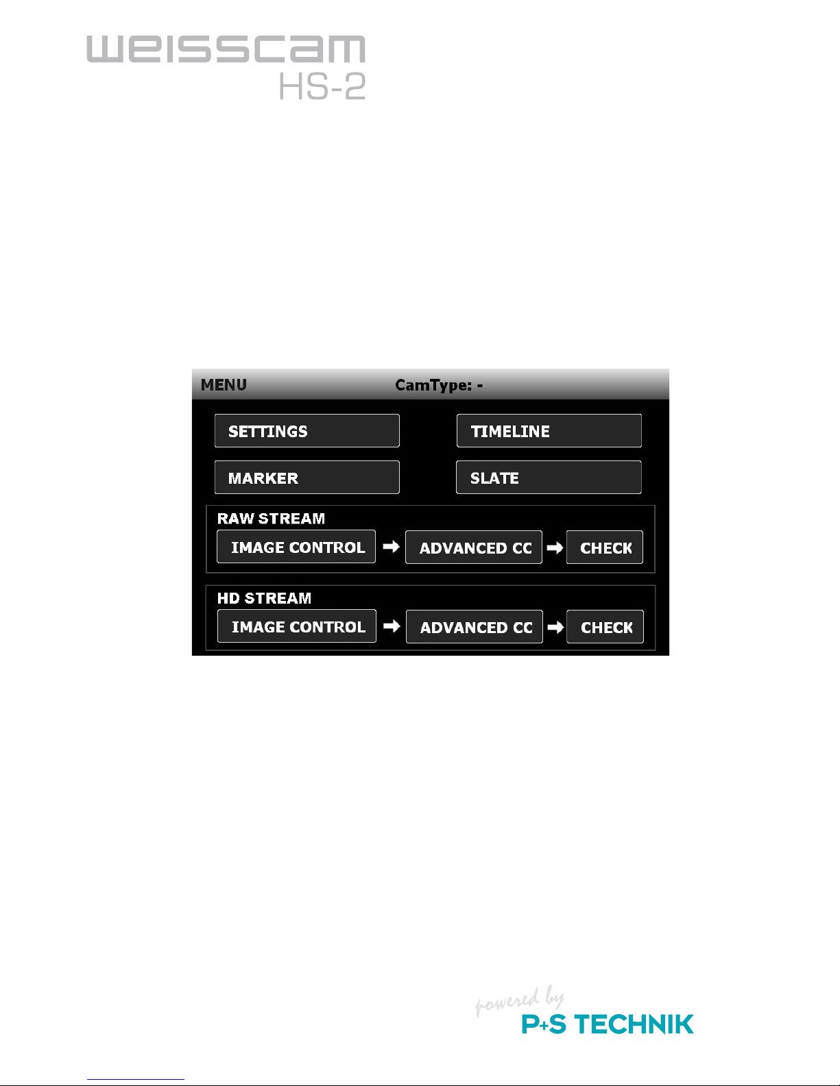
Hand Unit HU-2 (for stand alone version)
To switch on the WEISSCAM Hand Unit HU-2, hold the blue ON/OFF button on the left side
pressed for one second.
If everything is wired properly and supplied with power, the Hand Unit HU-2 boots up and the
WEISSCAM Software is started and automatically detects the camera.
The WEISSCAM HS-2 logotype appears in the window frame on the right side next to CamType.
If "No Camera", is displayed instead of "WEISSCAM HS-2", there is no connection and the camera
cannot be controlled.
For potential causes and solutions, refer to the "Troubleshooting" chapter.
Table of contents


