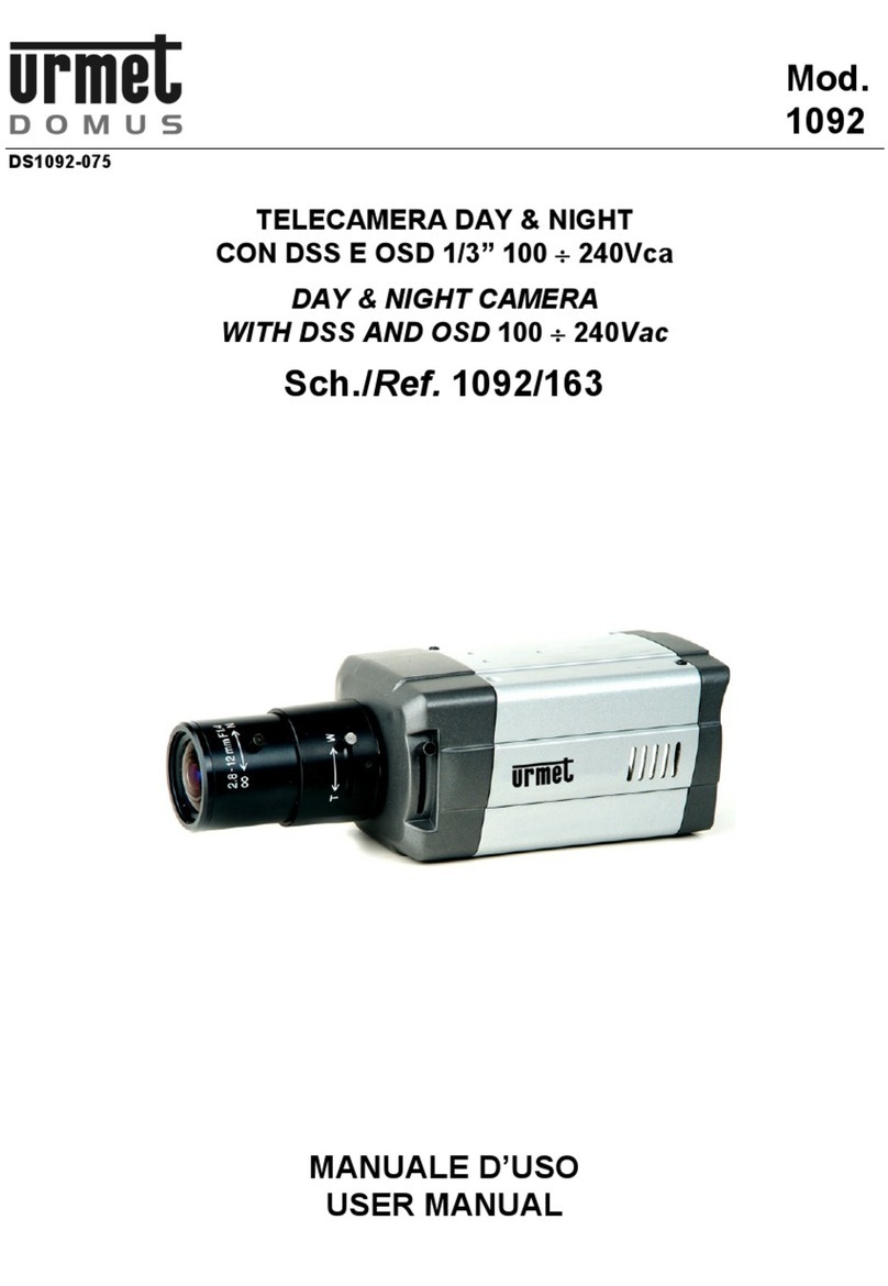
urmet domus 1099/214B User manual

DS1099-160
Mod.
1099
WIFI 3MP IP PoE CAMERAS SERIES
BULLET
1099/214B
1099/216B
USER MANUAL

2DS1099-160
CONTENTS
CONTENTS.............................................................................................................................................................2
INTRODUCTION.....................................................................................................................................................3
1PRODUCT DESCRIPTION............................................................................................................................3
1.1 Technical specifications...............................................................................................................3
1.2 Opening the package...................................................................................................................3
1.3 Warnings......................................................................................................................................4
2SIMPLIFIED EU DECLARATION OF CONFORMITY ..................................................................................5
3INSTALLATION.............................................................................................................................................5
3.1 1099/214B→WiFi Bullet fixed lens camera.................................................................................5
3.2 1099/216B →WiFi Bullet Varifocal camera.................................................................................6
4HOW TO CONFIGURE THE CAMERA IN A NETWORK.............................................................................6
4.1 How to add the camera to a WiFi network from the App .............................................................6
4.2 How to add the camera to a WiFi network using a smartphone browser ....................................7
4.3 How to add the camera to a cabled network and connect from the App...................................10
4.4 How to add the camera to a WiFi network using LAN cable and PC ........................................10
4.5 How to add the camera to a WiFi network using AP mode and PC ..........................................12
4.6 Static IP address allocation........................................................................................................12
5EASYTOOL .................................................................................................................................................13
6ACTIVEX CONTROL CONFIGURATION ...................................................................................................14
7CONNECTION FROM OTHER WEB BROWSERS....................................................................................15
8IP CAMERA WEB PAGE CONFIGURATION.............................................................................................15
8.1 Live.............................................................................................................................................15
8.2 Playback.....................................................................................................................................16
8.3 Remote settings.........................................................................................................................17
8.3.1 Display............................................................................................................................................... 17
8.3.2 Network.............................................................................................................................................. 19
8.3.3 Alarm.................................................................................................................................................. 25
8.3.4 Record ............................................................................................................................................... 27
8.3.5 System............................................................................................................................................... 28
8.3.6 Advanced........................................................................................................................................... 31
8.4 Local settings .............................................................................................................................34
8.5 Output ........................................................................................................................................34
9TECHNICAL SPECIFICATIONS.................................................................................................................35
10 APPENDIX...................................................................................................................................................36
10.1 FAQ............................................................................................................................................36
ENGLISH

DS1099-160 3
INTRODUCTION
Dear Customer,
Thank you for purchasing this product. We invite you to rear this manual carefully before starting any operation. The software
can be updated at any time. Consequently, the contents of this instruction manual are subject to change without prior notice.
Notes:
➢IPC standard for Internet Protocol Camera.
➢Select: left click.
➢Double click: left click twice.
➢Default IP address of the IP camera enabled in absence of DHCP: 192.168.1.168.
➢Default username of the camera IP: admin (lower case); Password: admin (lower case).
➢Default web port: 80. Default web port: 6066. Command port: 6060.
➢To avoid IP address conflicts, it is advisable to connect and configure one IP camera on the network at a time.
➢The content of this manual could be different from your current version. Please contact Urmet Technical Customer
Care if you encounter problems during operations. The manual will be regularly updated without prior notice.
1 PRODUCT DESCRIPTION
URMET devices Ref. 1099/214B, Sch. 1099/216B are wireless IP cameras which may be controlled entirely by connecting to
the TCP/IP network.
1.1 Technical specifications
➢High-performance CMOS sensor.
➢Optimised H.264/H.265 video compression algorithms; multi-stream transmission for high-definition images on
broadband and narrowband media.
➢Simultaneous connection
➢With integrated web server, Internet Explorer can be for real-time monitoring, setting and managing from the website.
➢Mobile software based on the following platforms: iOS (iPhone), Android (Smartphone).
➢Possibility to record on micro-SD card (not included) or on IP HVR/NVR device (not included).
➢Remote system updates supported.
➢LAN and Internet supported.
➢ONVIF protocol supported.
➢Various network protocols supported, such as HTTP, TCP/IP, IPv4, RTSP, UDP, SMTP, NTP, DHCP, DNS.
➢Alarm function supported on movement detection (the user can set area and sensitivity).
➢Privacy area function supported.
➢Wireless connection function.
➢Snapshot function. Image uploading from email.
➢Automatic reset function supported. Can be connected automatically in case of network interruption.
Note: the specifications of the various products may be subject to minor changes.
1.2 Opening the package
Check that the packing and the contents are not visibly damaged. Contact the retailer immediately if parts are either missing
or damaged. Do not attempt to use the device in this case. Send the product back in its original packing if it is damaged.
ACCESSORIES PROVIDED
➢1 WIFI IP camera
➢1 URMET quick guide on paper
➢1 Addendum QR code URMET APP V-Stream on paper
➢1 OSS Notice on paper
➢1 aerial (1099/214B, 1099/216B)
➢1 first installation kit containing fixing screws and/or hex wrench and/or tools for opening the device
➢2 hex wrenches (1099/214B, 1099/216B)
IMPORTANT NOTE:
Accessories may vary without prior notice.

4DS1099-160
1.3 WARNINGS
Power
➢Make sure that the rating plate data corresponds to the power specifications before connecting the device to the
mains.
➢Arrange a suitable circuit breaker and fuse upstream of the devices.
➢Disconnect power by means of the circuit breaker in the event of a failure and/or bad operation.
Safety precautions
➢Keep the device away from rain and humidity to prevent the risk of fire and electrocution. Do not introduce material
(solid or liquid) inside. If this should accidentally occur, disconnect the device from the mains and have it inspected
by qualified personnel.
➢Never open the device. In all cases, contact a qualified personnel or authorised service centre for repairs.
➢Keep the device away from children to prevent accidental damage.
➢Do not touch the device with wet hands to prevent electrical shock or mechanical damage.
➢Do not use the device if it should fall or the external casing is damaged. Risk of electrocution if the device is used in
such conditions. Contact the retailer or authorised installer.
Installation precautions
➢Do not install the camera in environments exposed to rain or humidity. Use specific boxes if required.
➢Avoid pointing the lens directly towards the sun or intense sources of light also when the camera is off. The subject
must not be backlit.
➢Do not point the camera towards reflecting objects or mirrors.
➢Some lighting systems (e.g. coloured fluorescent lights) may false the colours.
➢Do not arrange this device on an unstable surface, such as a tottering or slanted table. The device could fall causing
injury or mechanical failures.
➢Stop using the device if water or other material should penetrate inside: risk of fire and electrocution. Contact the
retailer or authorised installer.
➢Do not cover the device with a cloth while it is running to prevent deforming the external casing and overheating the
internal parts: risk of fire, electrocution and mechanical failure.
➢Keep magnets and magnetised objects away from the device to prevent faults.
➢Do not use the device in presence of smoke, vapour, humidity, dust or intense vibrations.
➢Wait for a while before operating a device immediately after transporting it from a cold place to a warm place and
vice versa. Wait on average for three hours: this will allow the device to adapt to the new ambient (temperature,
humidity, etc.).
Precautions
➢Make sure that the device is intact after removing it from the package.
➢Check that the working temperature is within the indicated range and that the environment is not excessively damp.
➢Do not point the camera towards the sun to prevent damaging the sensor.
Cleaning the device
➢Rub delicately with a dry cloth to remove dust and dirt.
➢Dip the cloth in neutral detergent if dirt cannot be removed with a dry cloth alone.
➢Do not use spray products to clean the device. Do not use volatile liquids (such a petrol, alcohol, solvents, etc.) or
chemically treated clothes to clean the device to prevent deformation, deterioration or scratches to the paint finish.
➢Disconnect the device from the mains before cleaning or maintenance.
Image recording
➢This device was mainly designed to transmit and possibly record images, not as a burglar alarm. Urmet S.p.A. cannot
be held liable for loss or damage following theft sustained by the user.
➢Test recording before using the device to make sure that is working correctly. Please note that Urmet S.p.A. is not
liable for loss of stored data consequent to loss or damage caused by incorrect installation, use, improper use or
malfunctioning of the device.
➢This device contains precision electronic components. Protect the device from shocks to ensure correct recording of
images.

DS1099-160 5
Privacy and Copyright
➢The IP camera is a CCTV system device. Recording of imagines is subject to the laws in force in your country.
Recording of images protected by copyright is forbidden.
➢Product users shall be responsible for checking and respecting all local rules and regulations concerning monitoring
and recording video signals. The manufacturer SHALL NOT BE LIABLE for use of this product not in compliance with
the laws in force. For more information see http://www.garanteprivacy.it.
Firmware upgrades
➢It is advisable to periodically check the Urmet website in the product-specific section for software and/or firmware
updates (go to www.urmet.com in the Products section "VIDEOSORVEGLIANZA AREA", type the reference product
code in the search field and move to DOCUMENTATION AND RESOURCES).
Network configuration
➢The camera is set to DHCP mode. If the network on which it is installed does not support dynamic addresses (DHCP),
the camera will automatically activate the default IP address 192.168.1.168. The “Easy Tool” Urmet software can be
used to change the default IP address and other network configurations of the camera to prevent conflicts with other
devices on the network. Always check the warnings for restrictions concerning the address which can be assigned
to the camera.
Network connections
➢When connecting a PC (using Software Client or Browser), any video channel on the PC will be using “unicast” connection
(TCP, RTP, UDP).
➢The device can support a limited number of “unicast” connections so it is possible to show the video on maximum 4 remote
devices (of which 2 smartphones at the most) at the same time depending on the available network band.
Reset button
➢Press for at least 3 seconds: the camera is completely reset and goes back to default settings.
IMPORTANT NOTE: the camera loses network configuration and the WiFi interface returns to Access Point mode.
2 SIMPLIFIED EU DECLARATION OF CONFORMITY
Hereby, URMET S.p.A. declares that the radio equipment types: cameras 1099/214B, 1099/216B, are in compliance with
Directive 2014/53/EU. The full text of the EU declaration of conformity is available at the following internet address:
www.urmet.com
3 INSTALLATION
3.1 1099/214B→WIFI BULLET FIXED LENS CAMERA
It is advisable to proceed as follows for correct camera installation and configuration:
1. Make sure that no units are powered before starting the installation procedure. Fit the aerial on the camera. It is advisable
to install and configure one camera at a time if you are installing multiple cameras on the same network.
2. Connect the camera to the network (see section 4). It is advisable to check that the WiFi signal received by the camera
is higher than or equal to 60.
3. Position the camera in a point on the wall or other surface and adjust the bracket to frame the required scene.
4. If you want the camera to record and store video files on a micro SD card (not included), plug the card into the slot when
the camera is powered off (see the picture below). Power on the camera and use the camera’s wepgabe or the app to
format the card before starting the recording function.
5. If you are using a NVR/HVR device, assign a static IP address to the camera and use the NVR/HVR menu to add the
camera to a recording channel.

6DS1099-160
3.2 1099/216B →WIFI BULLET VARIFOCAL CAMERA
It is advisable to proceed as follows for correct camera installation and configuration:
1. Make sure that no units are powered before starting the installation procedure. Fit the aerial on the camera. It is advisable
to install and configure one camera at a time if you are installing multiple cameras on the same network.
2. Connect the camera to the network (see section 4). It is advisable to check that the WiFi signal received by the camera
is higher than or equal to 60.
3. Position the camera in a point on the wall or other surface and adjust the bracket to frame the required scene. Make sure
that the frame and the zoom level is correct. Adjust the bracket again and lock it in its final position.
4. If you want the camera to record and store video files on a micro SD card (not included), plug the card into the slot when
the camera is powered off (sse the picture below). Power on the camera and use the camera’s wepgabe or the app to
format the card before starting the recording function.
5. If you are using a NVR/HVR device, assign a static IP address to the camera and use the NVR/HVR menu to add the
camera to a recording channel.
4 HOW TO CONFIGURE THE CAMERA IN A NETWORK
In this section explanation is provided to configure the camera in the network and to connect it remotely from the smartphone
App or from a PC.
IMPORTANT NOTE: the camera is provided with two different network boards, one for the wire connection and one for the
WiFi connection, each with its own MAC address and is own IP address.
4.1 HOW TO ADD THE CAMERA TO A WIFI NETWORK FROM THE APP
The camera can be quickly configured on the WiFi network using a smartphone, to do so refer to the Quick Guide of the Urmet
App V-Stream:
V-Stream

DS1099-160 7
Alternatively, the camera can be also configured on the WiFi network without making use of the smartphone, i.e. using a PC
in either way: by temporarily wiring the camera to the LAN (see § 4.4) or in ACCESS POINT mode (see § 4.5).
4.2 HOW TO ADD THE CAMERA TO A WIFI NETWORK USING A SMARTPHONE BROWSER
The camera can be easily configured on the WiFi network using the smartphone browser:
Open the WiFi settings of the smartphone and select the SSID of the camera in AP (Access Point) mode, the SSID is of the
URM_ type as in the image below :
Wait for the connection icon to change from 3G (or other) to Wi-Fi. This may take a few minutes.

8DS1099-160
Once the smartphone is connected to the camera's Wifi, using any smartphone browser, open the camera's web page at the
address http://223.223.100.1 by logging in with User Name: admin, Password: admin
After logging in, the Wi-Fi management page of the camera opens directly, pressing the Search button displays the list of
Wi-Fi networks detected by the camera.
IMPORTANT: if your smartphone offers to switch to another Wi-Fi network to access the Internet, refuse the change to stay
on the current Wi-Fi network and keep the connection with the camera.

DS1099-160 9
Select the Wi-Fi corresponding to the internet router to which you want to connect the camera and enter the router's Wi-Fi
network password, then press Saveand wait for the message Saved! lower in the page:

10 DS1099-160
At this point the smartphone automatically gets disconnected from the camera which is no longer in AP (Access Point) mode,
the camera is therefore connected to the internet router.
IMPORTANT: from factory settings the camera works in DHCP mode therefore it automatically receives a dynamic IP address
assigned by the router.
Use the URMET V-Stream APP available on the Stores to add the camera by scanning the local network or the QR code label
on the device and view images on smartphones through the internet:
V-Stream
To connect to the camera also from a PC workstation, use the “EasyTool” software (see following sections).
4.3 HOW TO ADD THE CAMERA TO A CABLED NETWORK AND CONNECT FROM THE APP
Use a LAN cable to connect the camera to the internet router then power the camera, itwill get a dynamic IP addressassigned
by the router’s DHCP service. If the DHCP service is not available on the network, the camera will automatically assign the
default IP 192.168.1.168 to itself.
Download the URMET App V-Stream from the store and use it to connect to the camera by simply scanning its QR code label,
then it will be possible to display the camera’s pictures on the smartphone through the internet:
V-Stream
Use the software “Easy Tool” to search and to connect to the camera from a PC (see below sections).
4.4 HOW TO ADD THE CAMERA TO A WIFI NETWORK USING LAN CABLE AND PC
Use a network cable to connect the camera to the LAN and power it. The camera will receive an IP address assigned
automatically by the DHCP service of the network. If the DHCP service is not available on the network, the camera will
automatically assign the default IP 192.168.1.168 to itself.
The following steps are needed for configuration:
1. Start “EasyTool” on the PC by selecting : the IP address, subnet mask, gateway and MAC
address of each IP camera active on the LAN will be automatically displayed, as shown in the figure below.
2. After having detected the IP camera, right-click and select “Open in IE” to open a Web page on IE.

DS1099-160 11
See the applicable section in the complete manual if installation of an ActiveX component is required.
You can select user name (default: admin), password (default: admin), stream type (Main/Sub Stream) and
language on the login page.
3. At this point, select “Login” to open the LIVE page.
4. Select the “Remote Setting” menu and then the "Wireless" menu under “Network” on the left.
5. Press the “Search” button to open the following page showing all the available WiFi networks and the signal power
detected for each one:

12 DS1099-160
6. Select the SSID of the WiFi network you want to connect the camera to, enter the network key and save the
configuration by pressing the “Save” button. It is advisable to check that the WiFi signal received by the camera is
higher than or equal to 60.
7. Disconnect the network cable from the camera to switch it to WiFi mode. Press the “Refresh List” button of
“EasyTool”to check that the camera appears again when it is connected to the WiFi network.
8. If you want the camera to record and store video files on a micro SD card (not included), plug the micro SD card
into the slot when the camera is powered off. Power on the camera and use the camera’s wepgabe or the app to
format the card before starting the recording function.
If you are using a NVR/HVR device it is advisable to assign a static IP address to the camera: see § 4.6 of this
guide to perform this operation.
4.5 HOW TO ADD THE CAMERA TO A WIFI NETWORK USING AP MODE AND PC
This mode is used to configure the wireless network interface of the camera without wiring it to the network and using a PC. It
is an alternative to § 4.4.
The camera is automatically set to Access Point mode if it wasnever configured in a WiFi network. A PC with wireless network
board is needed to configure it. In this case, network configuration may be performed after having fitted and powered the
camera in its final position.
The following steps must be performed for configuration:
1. Search from the available WiFi networks on the PC. The camera has a “URM_...” SSID. Select this SSID to connect
the PC to the camera.
2. Run steps from 1 to 6 described above in § 4.4. When asked for the camera's Wi-Fi network password, enter:
01234567
3. When the camera connects to the configured WiFi, it stops working in Access Point mode and disconnects from the
PC. For this reason, the PC must be connected to the LAN before pressing the “Refresh List” button of the “EasyTool”
program and detect the camera again in the network.
4. Run step 8 described above in § 4.4.
4.6 STATIC IP ADDRESS ALLOCATION
The network parameters of the camera, such as IP address, subnet mask and gateway may be set and modified using
“EasyTool” provided or on the camera web page.
If the camera has to be recorded by a HVR/NVR device it is advisable to set a static IP address after having appropriately
connected and configured the camera in the network (see previous sections). Make sure that the IP address you want to
assign to the camera is not already used in the network. It is better to use an address outside the range of addresses assigned
by means of DHCP.
To assign the static IP address, select the camera after having detected it in “EasyTool”. As shown in the figure below, fill in
the static network parameter to be assigned (the fields are filled in automatically by selecting the correct network interface
from those available on the PC) in the specific section of the tool.
Press “Modify IP Address” to change the IP address of the device and wait for a few instants.

DS1099-160 13
Press the “Refresh List” button of “EasyTool” to refresh the list and view the camera with the changes made.
IMPORTANT NOTE: to set/edit the network parameters of the camera (IP address, subnet mask, gateway) it is advisable to
use EasyTool or the web page of the camera. It is not advisable to set/edit the network configurations of the camera in the
NVR/HVR menus on which the camera was added; make sure that the NVR/HVR device is updated to the latest firmware
version.
5 EASYTOOL
The software can detect the IP address of the IP camera on the LAN. Firstly, download the easytool.zip file from the Urmet
website and unzip it.
Install and run EasyTool.exe.
Start “Easy Tool” by selecting : the IP Address, Subnet Mask, Gateway and MAC Address will be
automatically shown for each IP camera, as shown in the following figure.
If the searched IP and the IP address of the PC are not on the same network segment, the IP address, the subnet mask and
other IP camera parameters can be changed by using Easy Tool.
Firstly, select the device the IP address of which you want to change and enter the new IP address, Subnet Mask and Gateway
values (Subnet Mask and Gateway may be inherited from the PC) and the username/password. Click on Modify IP Address
to change the IP address of the device.
IMPORTANT NOTE
The default IP address of the IP camera is “192.168.1.168”, the default username is “admin”, the default multimedia port
number is “6066” and the default command port is “6060”.

14 DS1099-160
6 ACTIVEX CONTROL CONFIGURATION
You will need to install the plug-ins when inspecting the IP camera using Internet Explorer (Edge running in IE mode) for the
first time. Set the browse protection level to install the plug-in. Select the menu [Tools/Internet Options/Security/Custom Level]
and for "ActiveX controls and plug-ins" select "Enable" or "Prompt", as shown in the following figure. For safety, reset the
default protection setting in IE after having viewed the IP camera image.
Plug-in installation method:
Enter the IP address of the IP camera on the IE address bar to inspect the IP camera. The controls will be loaded automatically
on the IP camera.
The plug-in installation window will appear. Click on "Install" to complete the installation automatically.

DS1099-160 15
7 CONNECTION FROM OTHER WEB BROWSERS
The camera web page can be accessed using a browser other than Internet Explorer, simply by keying in the IP address of
the camera on the navigation bar of the browser.
In this case, no additional components need to be installed and the displayed stream live consists in MJPEG video stream for
which selecting Main/Sub is not effective on the login home page.
IMPORTANT NOTE:
all the controls present on the lower bar of the live video (after login):
are available only if the Internet Explorer is used as browser after installing the ActiveX control of the camera on the PC.
These controls are not available when connecting to the web page of the camera using different browsers from IE.
8 IP CAMERA WEB PAGE CONFIGURATION
8.1 LIVE
Open Edge running in Internet Explorer mode or other browser and enter the IP address of the IP camera (e.g.:
http://192.168.1.168). The login window appears. Observe the following figure:
The user can select the Stream Type on the access interface (this selection is only effective for Internet Explorer).
Enter User name (default: admin) and Password (default: admin), select Language and click on “Login” to access the Live
interface, as shown in the following figure.
Right-click (on Internet Explorer with ActiveX only) to select the stream to be displayed (Main Stream, Sub Stream) and to
view the bitrate.

16 DS1099-160
Other Live interface buttons (on Internet Explorer with ActiveX only):
: this is used to search and playback the video files recorded in the camera’s SD memory card (not
included).
: This is used to access the device setup menu to set the various customised parameters;
: Snapshot, file type, saving path etc.;
: Close and go back to the login page;
: PTZ interface to control ZOOM and FOCUS (only for Autofocus camera models)
: Control button preview. From left to right,
the buttons are: Start/Stop live video, Switch On/Off the PC Mic (to send audio to the camera), Switch On/Off the PC Audio
(to receive audio from the camera), digital zoom, Start/Stop video recording on PC, Snapshot.
8.2 PLAYBACK
Click on to access the Playback interface:
Select one of the red dates within the selected month and push the button to display the video recorded files on
the time bar. Different colors refer to different recording Type (Normal, Manual, Alarm, Motion).
Use the button to start playing back the video.
To quickly position the playback time cursor on the time bar during the playback you can use the function:
and push Go while the video is playing.

DS1099-160 17
8.3 REMOTE SETTINGS
8.3.1 DISPLAY
1) OSD CONFIG
Click on (Remote settings) to access the Live interface OSD Config (default).
➢Name: IP camera name.
➢Channel Display: Enable/Disable. The display position can be customised.
➢Time Display: Enable/Disable. The display position can be customised.
➢Flicker Control: 50Hz/60Hz/Close
2) IMAGE CONTROL
Click on 【Display】→【Image Control】to access the following interface.

18 DS1099-160
➢IRCUT Mode: 3 modes:
oGPIO & Video Mode : default mode. The camera switches from colors to black and white (turning on the IR
LEDs) and vice versa based on the environment light detected by the external sensor integrated in the camera.
oColor Mode or Daytime: fixed setting as colors only, it never switches to B/W picture.
oBlack & White Mode or Night: fixed setting as B/W only, it never switches to color picture.
➢IR-CUT Delay: This is the IRcut delay time.
➢IR-CUT Reverse: Enable/Disable the inversion of the functionality
➢Image setting: This is used to adjust brightness, contrast saturation, hue, sharpness.
➢BLC (Back light compensation): This is used to Enable/Disable backlight compensation. This function can
compensate the shadows on the subject in case of exposure against sunlight. In some scenarios of use, the visual
field may contain a very bright background, such as a door or a window in full sunlight, with the observed subject
surrounded by the light field. In this case, the picture may appear dark and flat. Backlighting compensation may be
used to solve this problem.
➢3D Noise Reduction: Auto/Week/Normal/Strong
➢WDR: This enables or disables the WDR function: Weak, Normal, Strong.
WDR allows the camera to acquire highly contrasted images. In short, DR (dynamic range) shows the details of the
light part and the dark part of the image. A broader dynamic range shows richer layers and a vaster colour range.
➢Flip: 4 modes: Close, Leftright, Updown, Center.
➢White Balance: Auto, Manual, Incandescent, Warm, Fluorescent, Natural.
Manual: Manual gain adjustment of red and blue colours for the camera video.
Auto: Optimisation according to the current lighting conditions and method of the screen and video colour calibration
of the camera video colours.
➢Iris Type: Manual and automatic modes can be selected. The default mode is Auto.
➢Time exposure: Camera exposure level adjustment.
➢Gain: Automatic gain level AGC adjustment (Auto, 6dB, 12dB, 18dB, 24dB, 30dB, 36dB, 42dB).
3) PRIVACY ZONE
Click on 【Display】→【Privacy Zone】to access the following interface.
Privacy zone setting:
1. Click to enable the privacy zone.
2. Select the Privacy area to be activated from the available four (Window 1, Window 2, Window 3, Window 4).
3. Point to the corner in the bottom right of each Privacy area and drag the mouse to change the size. Then position the Privacy
area on the concerned area of the image.
4. Click on Save to activate the privacy area.

DS1099-160 19
8.3.2 NETWORK
1) Network configuration
Click on 【Network】→【Network Setting】to access the following network page.
This page can be used to display and set the parameters related to the LAN of the camera:
➢Type: DHCP, Static or PPoE. The default setting is DHCP.
➢Command Port: This is the command port of the IP camera. Default: 6060
➢HTTP Port: This is the web port of the IP camera. Defalut: 80
➢IP address: Camera IP address
➢Subnet Mask: Subnet mask of the IP camera.
➢Gateway: IP address of the gateway used to access the Internet
➢DNS1/DNS2: IP addresses of the DNS servers.
➢Media Port: This is the client port of the IP camera. Default: 6066
➢MAC address: This is the MAC address of the LAN board of the camera.
Only in the case that the camera has to be recorded by a network device HVR/NVR, it is advisable to set a static IP address
after having appropriately connected and configured the camera in the network. Make sure that the IP address you want to
assign to the camera is not already used in the network. It is better to use an address outside the range of addresses assigned
by means of DHCP.
Select “Type = Static” and fill in the following fields: IP address, Subnet mask, Gateway and DNS. Press Save to save the
changes.

20 DS1099-160
2) Video Stream
Click on 【Network】→【Video Streaming】to access the following interface.
➢Type: MainStream, SubStream.
➢The user can set: Resolution, FPS, Audio (if the camera model has audio input), Bitrate control: CBR/VBR and the
MainStream/SubStream Bitrate value.
➢Resolution: MainStream 3MP (2304x1296), 1080P(1920x1080), 720P (1280×720), SubStream (640×360).
➢FPS: max 20 for the Mainstream and 25 for the Substream
➢I Frame Interval: is an interval for improving image quality. By default it is set to 60 for the MainStream and 50 for
the SubStream.
➢Audio: enable/disable TLC audio input (if supported by the camera model).
➢Rate Control: Set the Bitrate management as CBR (Constant Bit Rate) or VBR (Variable Bit Rate, at 6 quality levels
from Best to Worst.
➢Bitrate: set the transmission speed to bits per second as manual (user-defined) or default value.
IMPORTANT NOTE:
It is possible to access the third stream of the camera which is a MJPEG stream, by inputting the following URL in any internet
browser’s navigation bar:
http://IP/Streams/1/4/ReceiveData
Description:
•IP: to be replaced with the actual IP address of the device
•The MJPEG stream resolution can be modified in the following section: 【Advanced】→【Snapshot Settings
】
IMPORTANT NOTE:
The HTPP URL to get single JPEG snapshots is the following:
http://IP/Snapshot/1/RemoteImageCapture?ImageFormat=2
This manual suits for next models
2
Table of contents
Other urmet domus Digital Camera manuals

urmet domus
urmet domus 1092 User manual

urmet domus
urmet domus 1092/163 User manual

urmet domus
urmet domus 1096/201 User manual

urmet domus
urmet domus 1092/252H User manual

urmet domus
urmet domus 1092/253H User manual

urmet domus
urmet domus 1092 User manual

urmet domus
urmet domus 3300/410 User manual

urmet domus
urmet domus 1092 User manual

urmet domus
urmet domus 1092 User manual

urmet domus
urmet domus DS1096-004 User manual