PPM ViaLiteHD HRS-5/6 HB Series User manual

HRS-[5,6]-XX-XX-XX-XXXX-HB-1 VIALITE OPTICAL SWITCH HANDBOOK
2
Instrument Care and Safety Information
Please read the whole of this section before using your ViaLiteHD product. It contains important
safety information and will enable you to get the most out of your Fibre Optic Link.
Electrical Safety
The ViaLiteHD chassis is a Safety Class 1 product (having metal case directly
connected to earth via the power supply cable).
When operating the equipment note the following precautions:
Hazardous voltages exist within the equipment. There are no user serviceable
parts inside; the covers should only be removed by a qualified technician.
There are no user replaceable fuses in the chassis mounted equipment.
Replacement should only be carried out by a ViaLite Communications
technician.
The Optical Switch does not have safety earth stud connection. A 3 pin power
lead with Earth MUST be used for supplying power to the Optical Switch.
ESD Precautions
The ViaLiteHD RF Fibre Optic Link is equipped with high frequency active
electronics, without the correct handing, they will be susceptible to damage.
Precautions for handling electro-static sensitive devices should be observed
when handling all ViaLiteHD modules.
Technicians should ensure that they use effective personal grounding (i.e.
ESD wrist strap etc.) when servicing the equipment.
Any equipment or tools used should be grounded to prevent static charge
build-up.
Good practice should be observed at all times, for reference see relevant
standards: EN 61340-5-1, “Protection of Electronic Devices from Electrostatic
Phenomena –General Requirements.”
Optical Safety
The ViaLiteHD RF Fibre Optic Switch may be connected to devices that contain
optical sources operating at C-Band (DWDM) 1530 to 1565nm.
These devices can be rated up to EN60825-1 as CLASS 3B radiation emitting
devices. A class 3B laser is hazardous for eye exposure. They can heat skin and
materials but are not considered a burn hazard. Use of laser protective eyewear
is recommended. Avoid all eye exposure to beams from class 3B lasers.
When operating the equipment note the following precautions:
Never look into the end of an optical fibre directly or by reflection either with
the naked eye or through an optical instrument.
Never leave equipment with radiating bare fibres –always cap the connectors.
Do not remove equipment external covers when operating.

HRS-[5,6]-XX-XX-XX-XXXX-HB-1 VIALITE OPTICAL SWITCH HANDBOOK
3
TABLE OF CONTENTS
1INTRODUCTION.............................................................................................................................4
1.1 Typical Deployment...............................................................................................................4
2CARE OF FIBRE OPTIC CONNECTORS......................................................................................8
2.1 Fibre optic cable & connectors..............................................................................................8
2.1.1 Connecting and disconnecting....................................................................................8
2.1.2 Cleaning optical connectors, cleaning before every use............................................8
2.1.3 Cleaning optical connectors, high levels of contamination.........................................8
2.1.4 FC/APC Connectors ...................................................................................................9
2.1.5 SC/APC Connectors.................................................................................................10
2.1.6 LC/APC Connectors..................................................................................................10
2.1.7 Minimum bend radius................................................................................................10
3OPTICAL SWITCH FEATURES....................................................................................................11
3.1.1 Optical Connectors ...................................................................................................11
3.1.2 Ethernet Communication (RJ45) Connections .........................................................11
3.1.3 Dual Redundant Power Supply.................................................................................11
3.1.4 Front Display Screen ................................................................................................11
3.1.5 Modes of Operation ..................................................................................................11
4USING THE OPTICAL SWITCH. CONTROL, INDICATORS AND ALARMS...............................13
4.1 Connecting the module.......................................................................................................13
4.2 Menu and Operation ...........................................................................................................13
4.2.1 Boot Sequence .........................................................................................................13
4.2.2 Startup main menu....................................................................................................13
4.2.3 Menu Operation........................................................................................................14
5INSTALLATION OF THE OPTICAL SWITCH...............................................................................15
5.1.1 Web Interface Access:..............................................................................................15
5.1.2 Menus .......................................................................................................................15
5.2 MiB Files..............................................................................................................................20
6PART NUMBERING......................................................................................................................21
7MAINTENANCE AND FAULT FINDING GUIDE...........................................................................22
8PRODUCT WARRANTY...............................................................................................................23

HRS-[5,6]-XX-XX-XX-XXXX-HB-1 VIALITE OPTICAL SWITCH HANDBOOK
4
1 Introduction
The ViaLiteHD RF Fibre Optic Links (FOLs) are a family of fibre optically coupled link systems designed
for the transmission of RF analogue signals over long distances for the communications market. ViaLite
Communications is a division of Pulse Power and Measurement Ltd (PPM).
The Optical Switch is available as two main variants, the HRS-5 2 Input to 1 Output or the HRS-6 2
Input to 2 Output. The HRS-5 is a standard SPDT optical switch, whereas the HRS-6 is commonly
termed as a baseball switch, where in one state Input A is connected to Output 1 and Input B is
connected to Output 2, and in the other state Input A is connected to Output 2 and Input B is connected
to Output 1.
ViaLite offers several variants of the Optical Switches to suit application-specific requirements such as
input power range, fibre connector type.
1.1 Typical Deployment
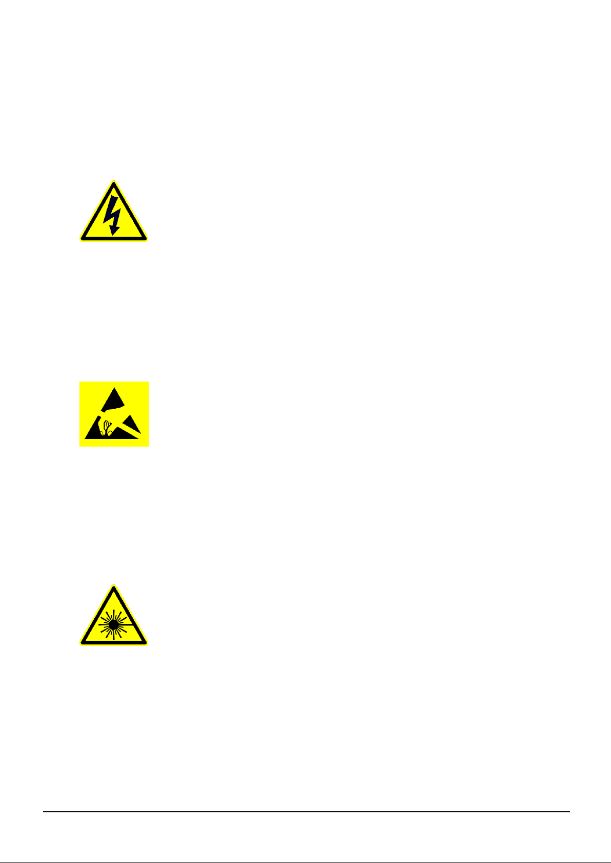
1.1.1 2 : 1 Redundancy
One use for a 2x1 optical switch is 2:1 optical link redundancy. An optical splitter is used to send the
optical signal down both the primary and the spare fibres. At the receiving end, an optical switch can
be used to pick which of the two fibres it should route through the receiver. With the built in power
monitoring of a ViaLiteHD 2x1 Optical Switch, the switch can detect if there is no light present on one
of the fibres, and then automatically switch to the backup fibre if required.
HRS-[5,6]-XX-XX-XX-XXXX-HB-1 VIALITE OPTICAL SWITCH HANDBOOK
5
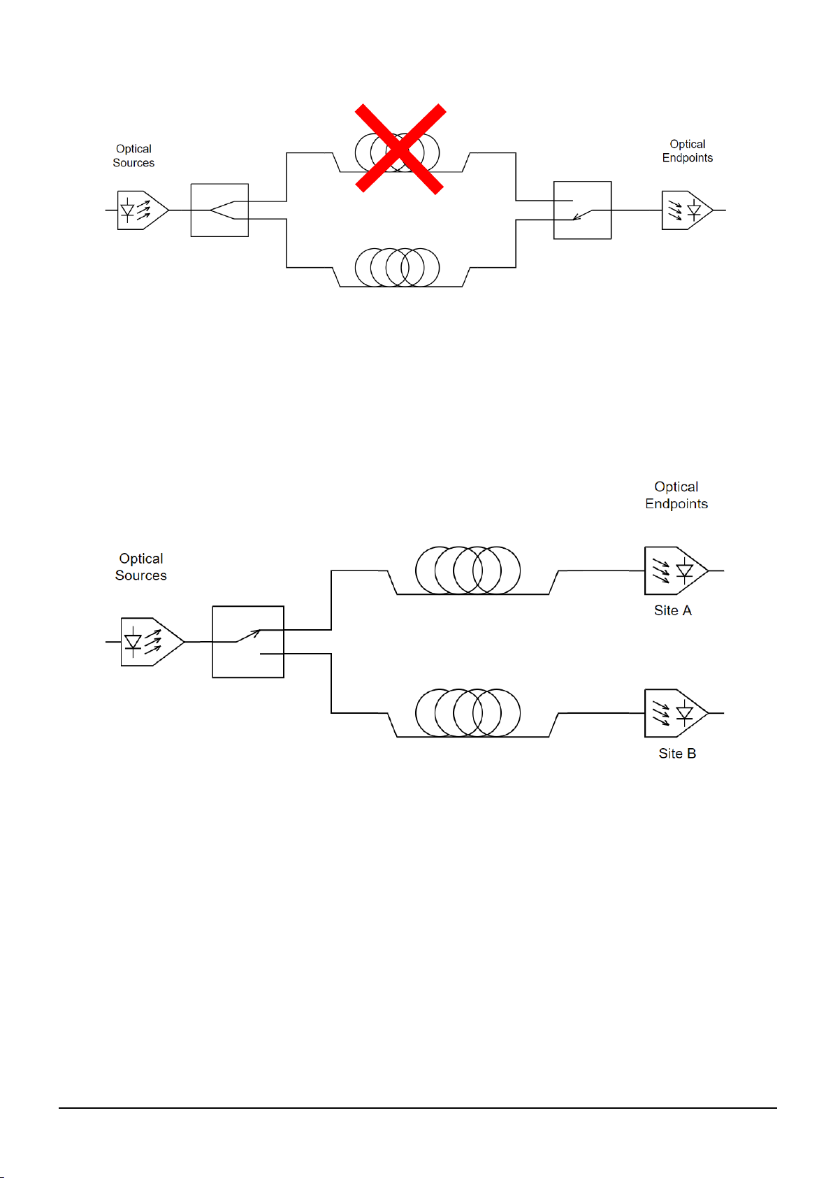
1.1.2 Site Diversity
To improve the reliability of satellite communications, it is common to have multiple ground stations in
different locations where if Site A’s communication link is heavily impaired by rain attenuation, the
communication link can be transferred to Site B which will be sufficiently far away from Site A that it
should not be affected by the same weather conditions. After receiving a remote switch command, a
ViaLiteHD Optical Switch can switch an RF over fibre (RFoF) signal from one site to another with
minimal delay, ensuring minimal disruption to the satellite communications.
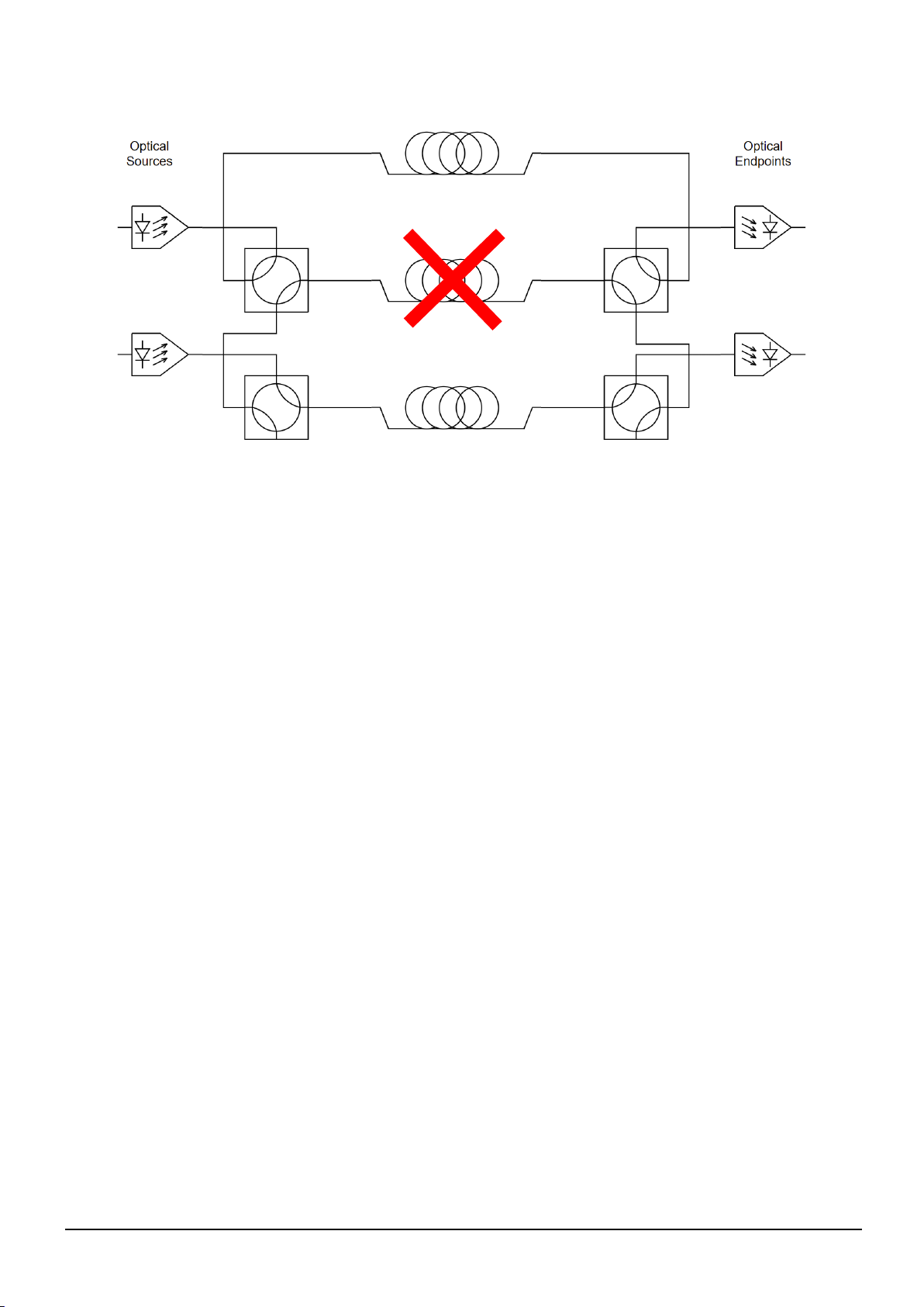
1.1.3 N+1 : N Redundancy
The primary use of the 2x2 Optical Switch is to provide link and equipment redundancy. One example
is a 3:2 redundancy where one spare fibre is available for use in the event that one of the other fibres
are damaged. The below image shows that equipment and link set up.

HRS-[5,6]-XX-XX-XX-XXXX-HB-1 VIALITE OPTICAL SWITCH HANDBOOK
6
The below image shows the first case where the bottom fibre is damaged. The optical path can be
switched through the spare fibre by switching the bottom two optical switches.
The below image shows the second case where the bottom fibre is damaged. The optical path can be
switched through the spare fibre by switching the top two optical switches.
HRS-[5,6]-XX-XX-XX-XXXX-HB-1 VIALITE OPTICAL SWITCH HANDBOOK
7

HRS-[5,6]-XX-XX-XX-XXXX-HB-1 VIALITE OPTICAL SWITCH HANDBOOK
8
2 Care of fibre optic connectors
When the fibre optic cables are not connected, it is essential that the cable and equipment connectors
are protected by the dust caps provided with the system. Failure to do so may result in damage to the
fibre ends, which are critical to the system performance. Please refer to section 2.2 for fibre optic cable
handling details.
2.1 Fibre optic cable & connectors
All ViaLiteHD RF modules use single-mode (9µm/125µm) cable terminated in a range of optical
connectors detailed below. Cross-site fibre optic cables are available from ViaLite Communications
as either standard patch leads or heavy-duty multicore cables.
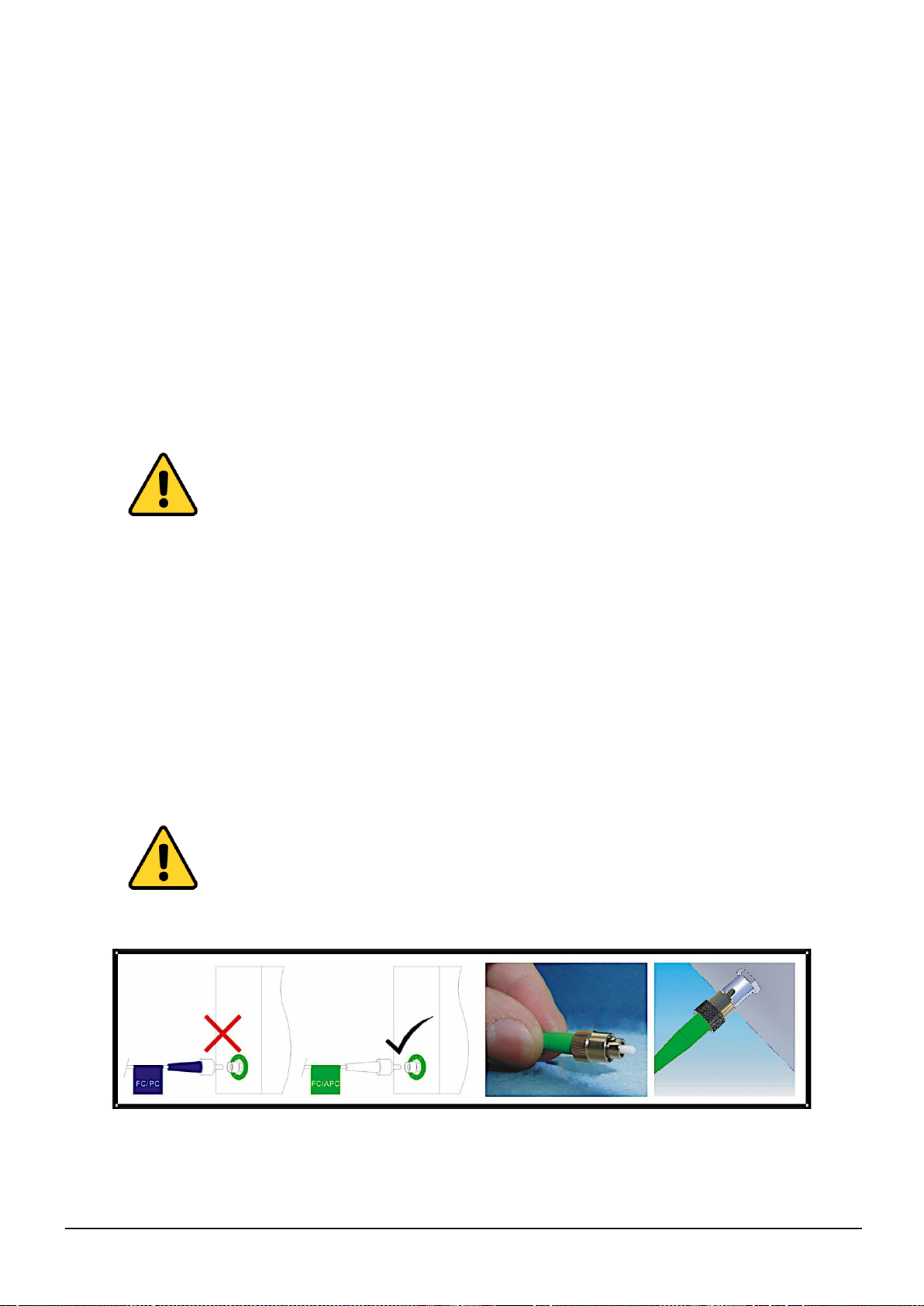
Warning!
Angle polished (APC) and standard (PC) connector must not be confused.
The two connector types are not interchangeable and mating one with the other will
damage both the cable and the module connectors.
The specification of optical connector is critical to the performance of the complete
fibre optic link. System performance can only be guaranteed with fibre optic cables
and connectors supplied by ViaLite Communications.
When FC/APC connectors are specified they must be “narrow key width.”
2.1.1 Connecting and disconnecting
Before connecting optical fibres to the module or to each other, ensure that the mating connectors are
clean (see below).
2.1.2 Cleaning optical connectors, cleaning before every use
Optical connectors MUST be cleaned before use, even where they have been protected with dust caps.
A large percentage of performance issues can be attributed to dirty fibres.
For more details please read the cleaning instruction which accompanies the connector cleaning kit.
Further details can also be found on the ViaLiteHD website at www.vialite.com.
2.1.3 Cleaning optical connectors, high levels of contamination
If there are performance issues that are not resolved by basic cleaning, then the following procedure
should be used. If the level of contamination is high it will be necessary to repeat this procedure.
Cleaning items required:
Lint free fibre cleaning tissues and/or cleaning sticks (normal cosmetic tissues produce dust and
are not acceptable).
Reagent grade Isopropyl Alcohol (IPA).
Air duster or filtered compressed air line.
Peel the plastic cover from an unused ‘N’
cleaning pad.
Hold the connector between your thumb and
forefinger
Clean the connector using firm pressure by
swiping in a pendulum motion through each
segment of the ‘N’shape, following the
diagram
Do not swipe over the same space twice.
HRS-[5,6]-XX-XX-XX-XXXX-HB-1 VIALITE OPTICAL SWITCH HANDBOOK
9
Cable Connector Cleaning
Dampen a patch of cleaning tissue with IPA and clean all surfaces of the plug ferrule.
Using a dry cleaning tissue, dry the ferrule and clean the end face.
Using the air duster, blow away any residue from the end of the connector.
Module Female Receptacle Cleaning (only recommended if problems are being experienced)
Either use an optical cleaning stick or twist a cleaning tissue to form a stiff probe, moisten either
with IPA. Gently push the probe into the receptacle and twist around several times to dislodge any
dirt.
Repeat the above process with a dry tissue.
Using the air duster, blow away any residue from the receptacle.
Important Notes
IPA is flammable. Follow appropriate precautions / local guidelines when handling and storing.
IPA can be harmful if spilt on skin. Use appropriate protection when handling.
It should only be necessary to clean the female receptacles on the modules if problems are being
experienced.
Warning!
Never inspect an optical fibre or connector with the naked eye or an instrument
unless you are convinced that there is no optical radiation being emitted by the
fibre. Remove all power sources to all modules and completely disconnect the
optical fibres.
2.1.4 FC/APC Connectors
To connect FC/APC optical connectors follow these steps:
Remove the dust caps and align the white ceramic center ferrule on the cable connector with the
mating receptacle.
There is a key (lug) on the side of the ferrule, which must match the keyway (gap) in the receptacle
shroud.
When they are aligned, gently push the plug home.
Finger tighten the knurled collet nut onto the threaded receptacle.
To disconnect follow these steps:
Using fingers fully unscrew the knurled collet nut, gently withdraw the connector.
Replace the dust caps on both the receptacle and the cable plug.
Warning!
It is possible to tighten the knurled collet without aligning the lug and gap. This
will result in poor light transmission. Check that the lug and gap are aligned
before tightening the knurled collet.

HRS-[5,6]-XX-XX-XX-XXXX-HB-1 VIALITE OPTICAL SWITCH HANDBOOK
10
2.1.5 SC/APC Connectors
To connect SC/APC optical connectors follow these steps:
Remove the plug protective cover.
Align the connector keyway slot in the adaptor to the key of the plug.
Gently push the plug-into the adapter until a click is heard and the connector locks.
To disconnect follow these steps:
Grip the body of the plug and gently pull the plug from the adaptor, replace the protective cover.
Only connect SC/APC cable to SC/APC receptacles.
2.1.6 LC/APC Connectors
All ViaLiteHD LC connectorised modules use LC/APC. Clean the plug, before inserting see section
2.1.2.
To connect LC/APC optical connectors
Remove the plug protective cover.
Align the connector latch to the adaptor.
Gently push the plug-into the adapter until a click is heard and the latch locks.
To disconnect:
Grip the body of the plug and push down on the latch.
While holding the latch down, gently pull the plug from the adaptor, replace the protective cover.
Only connect LC/APC cable to LC/APC.
2.1.7 Minimum bend radius
Because optical fibre is made of glass, it is important not to subject it to excessive stress. For this
reason, each type of cable has a minimum bend radius (MBR) specification, beyond which the cable
cannot be bent without permanent damage occurring. Systems using longer wavelength (i.e. 1550nm)
are less tolerant to small bend radii.
The minimum bend radius of standard SMF28 fibre optic cable fitted to ViaLiteHD modules is 50mm.
MBR specifications for ViaLite Communications supplied fibre optic cables are given in the ViaLite
Classic and ViaLiteHD System Handbooks Lxx-HB and Hxx-HB respectively.

HRS-[5,6]-XX-XX-XX-XXXX-HB-1 VIALITE OPTICAL SWITCH HANDBOOK
11
3 Optical Switch Features
This section describes the features of your Optical Switch; the available features may differ depending
upon the Optical Switch selected.
Please read fully all relevant documents for information on installing your ViaLiteHD equipment before
commissioning your system.
3.1.1 Optical Connectors
The ViaLiteHD Optical Switch is supplied with SC/APC input and output optical connectors as standard.
FC/APC & LC/APC options are also available.
3.1.2 Ethernet Communication (RJ45) Connections
An RJ45 connection on the rear of the unit offers web and SNMP network management control (see
section 5.1.1. for web interface access).
3.1.3 Dual Redundant Power Supply
The optical switch comes fitted with dual redundant power supplies. The power lead(s) are fed to the
rear of the equipment. Each power supply is activated by a dedicated power switch also on the rear.
3.1.4 Front Display Screen
The display screen on the front of the module allows the user to scroll through all menu items in turn.
This allows the user to set the IP configurations and to adjust operating settings where available.
3.1.5 Modes of Operation
Manual
HRS-5 2x1 Switch
The available Options are:
A to Out –Input A is routed to the Output, Input B is disconnected
B to Out –Input B is routed to the Output, Input A is disconnected
HRS-6 2x2 Switch
The available Options are:
A to 1; B to 2 –Input A is routed to the Output 1, Input B is routed to Output 2
A to 2; B to 1 –Input A is routed to the Output 2, Input B is routed to Output 1
Automatic
HRS-5 2x1 Switch
If optical power is detected at Input B when there is no optical power detected at Input A, then Input
B will be routed to the Output
If the optical power detected at Input B is greater than the set Optical Switch Point while the optical
power at Input A is below the Optical Switch Point, then Input B will be routed to the Output
In all other conditions, Input A will be routed to the Output

HRS-[5,6]-XX-XX-XX-XXXX-HB-1 VIALITE OPTICAL SWITCH HANDBOOK
12
HRS-6 2x2 Switch
If optical power is detected at Input B when there is no optical power detected at Input A, then Input
B will be routed to Output 1 and Input A will be routed to Output 2
If the optical power detected at Input B is greater than the set Optical Switch Point while the optical
power at Input A is below the Optical Switch Point, then Input B will be routed to Output 1 and Input
A will be routed to Output 2
In all other conditions, Input A will be routed to the Output 1 and Input B will be routed to Output 2

HRS-[5,6]-XX-XX-XX-XXXX-HB-1 VIALITE OPTICAL SWITCH HANDBOOK
13
4 Using the Optical Switch. Control, Indicators and Alarms
4.1 Connecting the module
All instructions refer to the representation of the front panel shown in the diagram below. The user can
scroll through the menus by using the push buttons located to the right of the LCD screen and scrolling
to select all the menus of the optical switch.
4.2 Menu and Operation
These devices are fitted with four LED’s to indicate the current routing through the switch.
4.2.1 Boot Sequence
Plug in the power supply (to both ports if redundancy is required)
Turn on the power switch on the rear panel
Front Panel shows the part number
IN(A)-OUT(1), IN(A)-OUT(2), IN(B)-OUT(1), IN(B)-OUT(2) will light up depending on the model and
the current optical switching route
4.2.2 Startup main menu
Press Select button and the following menus will be displayed in sequence.
Menu #1 –Descriptor
Read only menu –Provides the device part number, and a description of the device
Menu #2 –Input A Wavelength
Read/write menu –Allows the wavelength of Input A to be changed between 1310nm and 1550nm
Menu #3 –Input B Wavelength
Read/write menu –Allows the wavelength of Input B to be changed between 1310nm and 1550nm
Menu #4 –Input A Power
Read only menu –Displays Input A’s optical power in dBm
Menu #5 –Input B Power
Read only menu –Displays Input B’s optical power in dBm
Menu #6 –Output Power
Read only menu –Displays the Output optical power in dBm
Menu #7 –Switch Type
Read only menu –Displays the Switch Type, either 2x1 or 2x2
Menu #8 –Switch Mode
Read/Write menu –Allows the switch mode of the device to be changed. The options available will
depend on the switch type
Menu #9 –Unit Temp
Read only menu –Displays the unit temperature in OC
Menu #10 –+5V Monitor
Read only menu –Displays the voltage of the +5V rail

HRS-[5,6]-XX-XX-XX-XXXX-HB-1 VIALITE OPTICAL SWITCH HANDBOOK
14
Menu #11 –-5V Monitor
Read only menu –Displays the voltage of the -5V rail
Menu #12 –Optical Switch Point
Read/write menu –Allows the optical power threshold to be set, at which point the device switches from
one path to the other
Menu #13 –IP Address
Read/Write menu –Allows the IP address of the device to be changed
Menu #14 –Subnet
Read/Write menu –Allows the subnet of the device to be changed
Menu #15 –Gateway
Read/Write menu –Allows the gateway of the device to be changed
Menu #16 –TRAP1
Read/Write menu –Allows the SNMP TRAP1 address to be changed
Menu #17 –TRAP2
Read/Write menu –Allows the SNMP TRAP2 address to be changed
Menu #18 –Serial Number
Read only menu –Displays the units serial number
4.2.3 Menu Operation
1. Setting the Automatic/Manual Optical Switching Mode (Menu #8)
Press Select until the Switch Mode Menu is visible. Press ▲to edit then press ▼until you have selected
the required mode, then press Select to save.
2. Setting the Optical Switching Threshold (Menu #12)
Press Select until the Optic Switch Mode is visible. Press ▲to edit then, use ▼to increment the value
or change the sign then use ▲to shift to the next digit. Press Select to Save.
3. Setting the Network/SNMP Settings
Press Select until the required menu is visible (IP/Subnet/Gateway/Trap Addr1/Trap Addr2), press ▲
to edit, use ▼ to increment the value then use ▲ to shift to the next digit. Press Select to Save.

HRS-[5,6]-XX-XX-XX-XXXX-HB-1 VIALITE OPTICAL SWITCH HANDBOOK
15
5 Installation of the Optical Switch
When installing the optical switch, ensure all fibre ports and connectors remain capped and fibres are
cleaned before connection. Whilst the optical switch does not contain any optical sources, it is likely to
be connected to a device with high power optical sources. Any optical sources in the system should be
switched off before connecting the optical switch.
The unit can be programmed with the IP settings for serial connection to access via Web Browser as
detailed here.
5.1.1 Web Interface Access:
Connect the LAN port of the computer and the optical switch, then turn on the power switch of the
device. Scroll through the menus to check the IP address. Open a web browser and enter the IP address
of the device (see section 3.1.2), then press “Enter”to bring up the following dialog box.
Enter both the username and password as “admin”and then click Sign In/OK. Ensure your laptop
settings are updated to match the device.
Web access dialog box username & password “admin”
5.1.2 Menus
Once connected to the optical switch, the following menus will be available.
IP Configuration menu (view and setup Network Settings)
Analog Property Menu (signal and alarm thresholds)
Discrete Property Menu (power status and control)
Device Configuration (set switch mode and switch point)
Device Status Menu (reporting of properties)
System Information
Event log
User Configuration Menu (setup password access)

HRS-[5,6]-XX-XX-XX-XXXX-HB-1 VIALITE OPTICAL SWITCH HANDBOOK
16
IP Configuration Menu
Analog Property Menu

HRS-[5,6]-XX-XX-XX-XXXX-HB-1 VIALITE OPTICAL SWITCH HANDBOOK
17
Discrete Property Menu
Device Configuration
HRS-[5,6]-XX-XX-XX-XXXX-HB-1 VIALITE OPTICAL SWITCH HANDBOOK
18
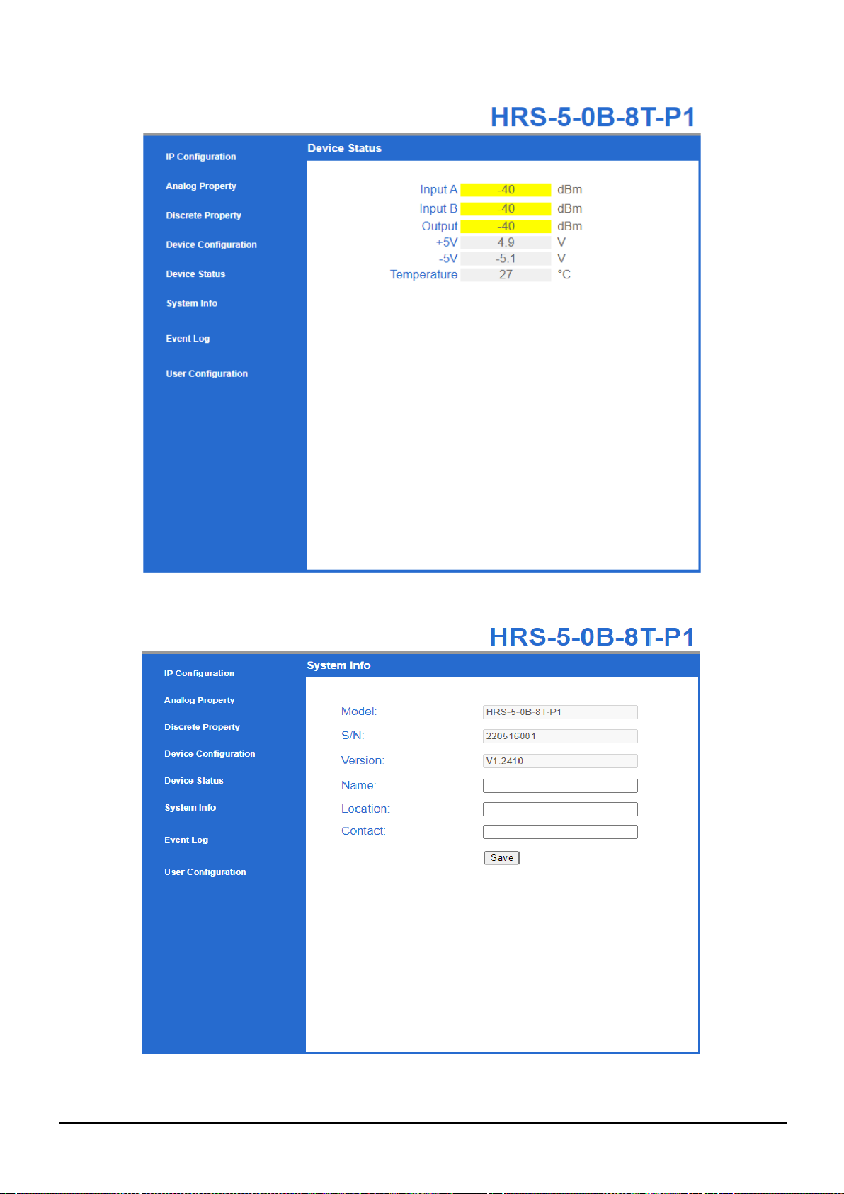
Device Status Menu
System Information
HRS-[5,6]-XX-XX-XX-XXXX-HB-1 VIALITE OPTICAL SWITCH HANDBOOK
19
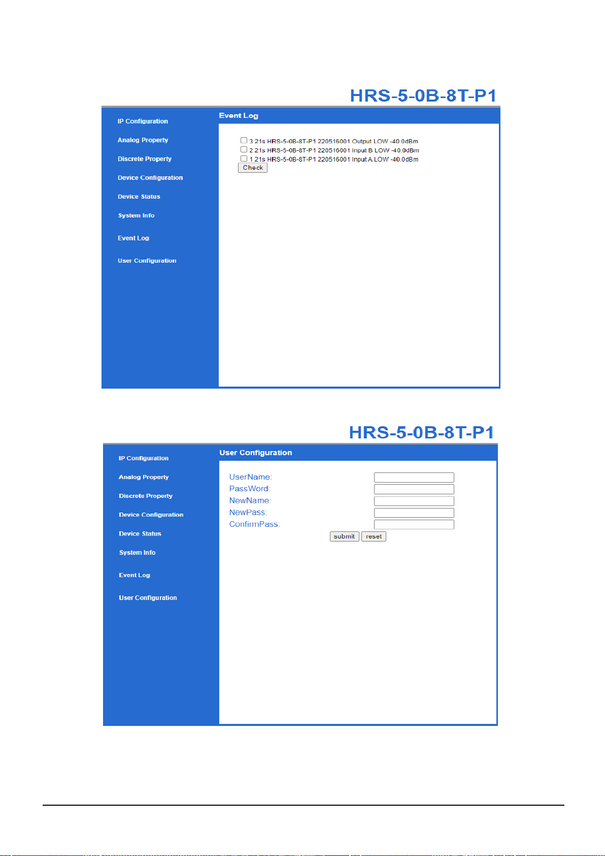
Event Log
User Configuration Menu

HRS-[5,6]-XX-XX-XX-XXXX-HB-1 VIALITE OPTICAL SWITCH HANDBOOK
20
5.2 MiB Files
The Optical Switch may be controlled and monitored via SNMP over the Ethernet interface.
For the latest Optical Switch MIB files, please contact your local ViaLiteHD distributor.
Table of contents
Popular Switch manuals by other brands


Renkforce
Renkforce 1610326 operating instructions

Belkin
Belkin F4U006 - Travel USB Hub Quick installation guide

Kiepe Elektrik
Kiepe Elektrik HES Series operating instructions

ZyXEL Communications
ZyXEL Communications GS1100 Series brochure

Honeywell
Honeywell XP-4051 installation instructions

F&F
F&F WB-2 quick start guide