5
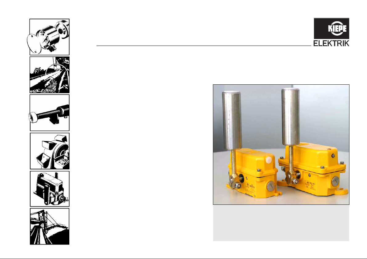
Operating instructions HES and SEL
1 For your safety
CONFIDENTIAL
1 For your safety
1.1 Intended use
The belt misalignment switches HES and SEL are used
for monitoring the true running of continuous conveyors.
The switches serve to protect the belts from being dam-
aged or destroyed if the belt deviates from its designed
running line. The device is intended for use in stationary
installations and vehicles.
The documentation at hand is to be considered part of
the product and must be retained and be available to the
respective owner/user for the entire service life of the
product. The documentation must be passed on to each
subsequent owner of the product.
The manufacturer is not liable for personal injury and
property damage arising from non-intended use of the
device or unauthorized modifications to the device and
its components. Make sure that the intended use is not
impaired in any way even after unexpected outside influ-
ence on the device.
Intended use refers specifically to the operation of the
device in accordance with these operating instruc-
tions. Work on this device may only be carried out by
qualified personnel who are familiar with accident pre-
vention regulations as well as other generally recog-
nized safety regulations.
By using the equipment as intended, you protect
yourself and prevent damage to the equipment and
its components.
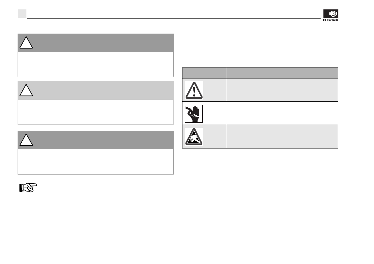
1.2 Design of warnings
Risks are classified in accordance with ISO 3864-2 and
ANSI Z535.6 using the keywords
•“Danger,” “Warning,” and “Caution” in the case of
bodily injury,
•“Beware” in the case of property damage, and
•“Note” to convey general information.
In this documentation, the Risks and Notes are classified
and presented as follows:
Danger!
indicates the immediate threat of danger. Not avoiding
this danger will result in death or extremely serious in-
jury (crippling).