PR Lighting AQUA 480 BWS User manual

2
INDEX
1.
SAFETYANDWARNINGS…………………………………………………………………………………
3
2.
INSTRUCTIONS……………………………………………………………………………………………
4
●CLEANINGANDMAINTENANCE………………………………………………………………………
4
●LUBRICATION……………………………………………………………………………………………
4
●TROUBLESHOOTING……………………………………………………………………………………
5
3.
APPEARANCE………………………………………………………………………………………………
5
4.
INSTALLATION ……………………………………………………………………………………………
6
●RIGGING …………………………………………………………………………………………………
6
●POWERCONNECTIONS ………………………………………………………………………………
6
●DMXCONTROLCONNECTIONS ………………………………………………………………………
7
●DMXTERMINATOR………………………………………………………………………………………
7
●ALIGNMENT/INSTALLATION/REPLACEMENTOFALAMP …………………………………………
8
●GOBOREPLACEMENT …………………………………………………………………………………
8
5.
SETUPANDCONFIGURATION……………………………………………………………………………
9
●FRONTPANELOPERATION ……………………………………………………………………………
9
●DMXSTARTADDRESS …………………………………………………………………………………
9
●DMXWIRELESSCONTROL………………………………………………………………………………
9
●STAND-ALONEMODE …………………………………………………………………………………
10
●MASTER/SLAVEMODE…………………………………………………………………………………
10
6.
OPERATION MENU…………………………………………………………………………………………
10
7.
DMXPROTOCOL……………………………………………………………………………………………
16
8.
SIGNSONTHETOUCHSCREEN…………………………………………………………………………
20
9.
ERRORMESSAGES………………………………………………………………………………………
20
10.
TECHNICALDATA…………………………………………………………………………………………
21
11.
CIRCUITDIAGRAMANDPCB CONNECTIONS…………………………………………………………
25
●CIRCUITDIAGRAM………………………………………………………………………………………
25
●PCBCONNECTIONS………………………………………………………………………………………
27
12.
COMPONENTORDERCODES……………………………………………………………………………
29
ACCESSORIES
Thefollowing itemsaresuppliedwith theprojectorand pleasecheck:
Name
Quantity
Unit
Remark
Gclamps
2
Pcs
XLR connector
1
Set
Maleand female
Safetycord
1
Pc
User manual
1
Pc
Ω clamps
2
Pcs
Optional
Please note that as part of our ongoing commitment to continuous product development, specifications are
subject to change without notice. Whilst every care is taken in the preparation of the manual we reserve the
right to change specifications in the course of product improvement. The publishers cannot be held responsible
for the accuracy of the information herein, or any consequence arising from them.
Every unit is tested completely and packed properly by the manufacturer. Please make sure the packing and /
or the unit are in good condition before installation and use. Should there be any damage caused by
transportation, consult your dealer and do not use the unit. Any damage caused by improper use will not be
assumed by the manufacturer and / or dealer.
Note: For the products made by Guangzhou PR lighting Ltd, the warranty for the whole product is one yearstarting from
thedeliverydatebutthelight sourceisnot withinthewarranty.

3
1. SAFETYANDWARNINGS
NOTE
Before a projector’s installation, power-on, operation and maintenance, please carefully read
the safety information hereinafter!
Thefollowingsafety signsareusedinthe usermanual.
Warning
User
Manual
Electrical
shock
Goggles
Protective
Gloves
Flames
High
Temperature
● When unpacking , check if there is transportation damage before using the projector. Should there be any
damagecausedbytransportation,consultyourdealeranddonotuseit.
●The manufacture is not responsible for loss caused by the user not following the manual or changing the projector
ashe/shelikes.
●Pleasebenotedthatthedamagecausedbychangingtheprojectoratwillisnot warranted.
●Do not hesitate to contact the dealer or the manufacturerifanyquestionsor advice.
● Theprojectoris forindoorand outdooruse,IP66.
● Itcanbeusedinhumidand dustyareas.And itcancontactwaterandothernon-corrosiveliquids.
●The projector should be kept away from high temperature, fire, electrical surge, vibration and strong light while
beingoperated
●The projector is only intended for installation, operation and maintenance by qualified personnel. And the
operationmuststrictlyfollowtheproceduresinthemanual
●No repairable partsintheprojectoranddonotopencoversformaintenancebyyourself.
●Don’t look straightly into the light sources especially for epileptics, otherwise eyes will be burned..
●Do notconnectthisdevicetoanytypeofdimmerpack.
●Afterlampswitchedon,theminimumdistancebetweentheprojectorandilluminatedsurfaceis 18m.
●lensandotheropticalpartsshallbereplacedimmediatelyiftheyhavedeformedorbeendamaged,otherwise the
lightoutputwillbe compromised.
●Before operation, please confirm that all covers(housing) are on and screws tightened. It’s forbidden to use a
projector whilecovers(housing)areoff.
●Keep thelamp cleanand do not touchit withbare hands.
●While operatingit, wearprotectiveitems.
●Anyelectricalconnectionmustbecarriedoutbyaqualifiedperson.
●Before installation,pleaseconfirmthe voltagesuppliedmatcheswhatisrequired fortheprojector.
●Eachprojectormustbeproperlyearthedand installedasper related electrical standards.
●Do notusepower cord withitsinsulatordamagedandconnectthepower cord withothercables.
●If the projector is not used or under cleaning,, please hold the plug and unplug it. Do not unplug it forcefully
orbypullingthepower cable.
●Allpowercordsmustconform torelatedsafetyandregulations.
●Whilebeingoperated,theprojectorshouldnotbeunderrainsorinhumidity.
●Do not switch on and off the projector constantly in very short intervals, otherwise the light source’s and other
electricalparts’ lifewillbeshortened .

4
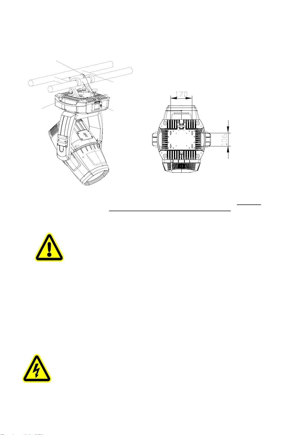
●There are safety cord holes at the bottom of the base of a projector. In view of safety, please run the safety
cord suppliedthroughthesafetycordholesfor safetysupport.
●Before any installation, maintenance and cleaning work, please ensure the projector is disconnected from
powermains.
●Afterrunningfor30minutes, thetemperatureofthehousingoftheprojectoris45℃.Afterstableoperation,
itstemperatureis75℃.
●While thelampisstrickenforthefirsttime,therewillbesmokeandstrangesmell.It’s normal and does not
mean theprojectorhassome defects.
●Do notmount theprojectordirectlyoninflammablesurface.
●Do notprojectthebeamstraightlyoncombustibleitemsand theminimumdistancebetweentheprojector
andilluminateditemsis18m.
●Aprojector should be installed with good ventilation and the minimum distance between the projector and
wallsis50cm.At thesametime,pleaseensurethefansandairinletsand outletsare workable.
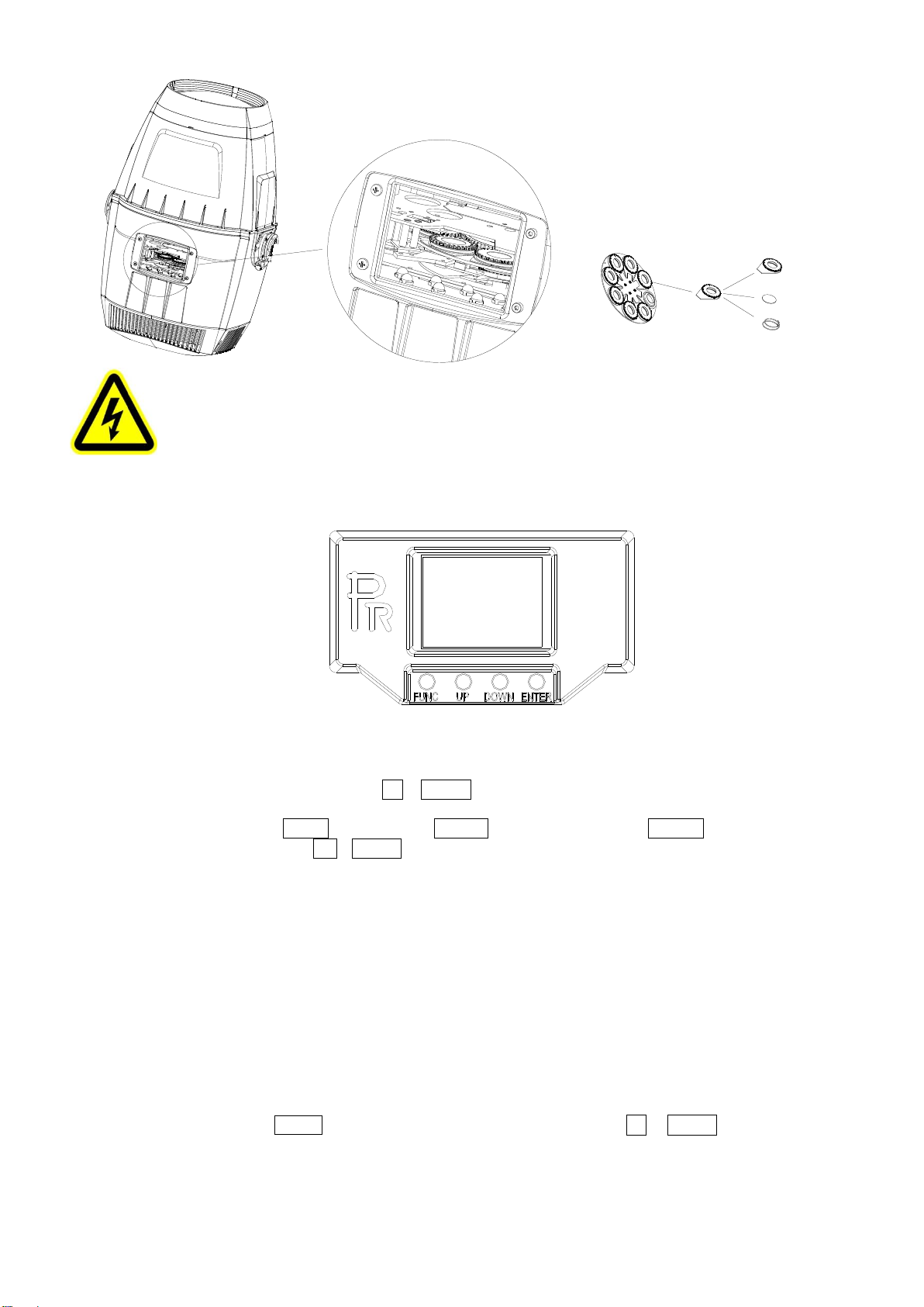
2. INSTRUCTIONS
●CLEANINGANDMAINTENANCE
If a projector can’t start. Please check if the fuse is blown up. If it does, replace it with a new fuse with same ratings. And the
projector has over-temperature protective device. Ifthe temperature is too high, the protective device will be triggered to shut the
projector off. When it happens, please check if the fans run normally or fan shield is blocked by dust. After the issue is solved,
restarttheprojector.
The accumulation of oil, smoke and dust on the lens will compromise the light output. Cleaning a projector is verynecessary to
ensure a reliable use of it. Cooling fans need to be cleaned every 15days. Internal lens, reflectorand hotmirror need to be cleaned
periodicallyto optimize lightoutput.
Cleaning frequency is to bedecided byoperations and its environment. Use soft clothand normal detergent for glass for cleaning
work. It’s advised external optical system be cleaned every 20days and internal optical systems every 30/60days. Keep lens clean
anddo not touch optical parts with bare hands.
Special note:
It’s normal phenomena that there will be mild water mist on the lens while the waterproof product is in use.
●Beforeanymaintenanceandcleaning,pleaseensuretheprojectisoffthepower.
●Onlyqualifiedpersonisallowed todo maintenance.
●During maintenanceandbeforemaintenance, the projectormustbe offpower.
●To avoid the sunlight or otherlight beampenetrates throughthe front lens into the head, which
results in high temperature internally and damaging the projector accordingly. Before
power-ff,please usetheTilt channeltolettheheadface down.
●Do notusealcoholor otherorganicsolvent to cleanthehousingtoavoiddamage.
●Do notuseany solventwithchemicalelementsto cleancolor filtersor hot mirror.
●LUBRICATION
To ensure smooth movement of gobos and zoom and focus lens, it’s advised rotators’ bearings and 2 sliding bars for zoom and
focuslensbelubricated every2 months. Highqualityand hightemperature lubricant/greaseisadvised..

5
●TROUBLESHOOTING
PROBLEM
ACTION
The projector doesn’t switch on
Checkthe fuseonthe power socket.
Checkthelamp.
Thelampison but the projector doesn’t respond
to the controller
Makesurethatthe fixture’s start address is right
Replace orrepair theXLRsignal cable.
Theprojector functions intermittently
Makesurethefanisworkingwellorfansandtheirshieldsarenotblocked
Beam appearsdim, Lowinbrightness
Make surethelamp is within itslifespan
Remove dustorgreasefromthe lenses.
Theprojectimageappears to have ahalo
Carefullycleanthelamp,opticallensesandothercomponents.
HeavilyDefectiveBeam
Checkif lensareingoodcondition(notcracked)
Cleandustorgrease on thelens.
3. APPEARANCE
1. FrontLens
2.Tilt Lock
3. PanLock
4. Base
5. FrontLensCover
6. UpperHeadCover
7. ChamberCover
8. LowerHeadCover
9. FanCover
10. PanLatch
11.TiltHandle
RearPaneloftheBase
1.Waterproofpowersocket
2.Waterprooffuseholder
3.Waterproof5-pinXLRSocket(Male)
4.Waterproof5-pinXLRSocket(Female)
5.WaterproofEthernetPort
6.WaterproofDMX Wireless Receiver(Only
forprojectorrequestedforwirelesscontrol)
7. Gore-Tex membrane
FrontPaneloftheBase
1. Return Key
2. UPKey
3. DownKey
4. Enter Key

6
4. INSTALLATION
●RIGGING
Before moving a projector, Please lock Pan and Tilt. Before its operation, please unlock them. It’s forbidden to run a
projectorwithpowerwhileit islocked.
Take 2 clamps and the safetycord out fromthe package and mount 2 clamps on the underside of fixture with 2 retainers attached
to each clamp. Hang the fixture on the structure and fasten the screws attached to each clamp. (See the WARNING on the
underside ofthe base as shown above) To pass the SAFETYCORD through the HOLES for safety! Always ensure that the
projector is firmlyanchoredto avoid vibrationand slippingwhilst functioning. Always ensurethatthestructurethatyouaregoing
to mountthe projector to issecureand strongenoughtosupporttheweightofaXR1000 Framing.
WARNING:
●The projectorMUSTbe liftedorcarried by theHANDLESinsteadofclamps.
●.Forsafetythesafetycordshould afford 10 times the Projector’s weight.
●POWERCONNECTION
Connectthe powercordasfollows:
L(live)=brown
E(earth)=yellow/green
N(neutral)=blue
Before power connection, please ensure the power supplied must match what the nameplate says. It is recommended that each
projectorbeconnected with powerseparatelyso thattheymaybeindividuallyswitchedonand off.
●The earth wire(yellow/green) must be connected to the ground. And electrical connection must be in
accordancewiththe standardsconcerned.
●Ifany questionsabouttheelectricalinstallation,do notcontinuebutconsulta qualifiedelectrician.
Control Panel
Handle
Clamp
Safety Cord Warning
Please run the safety cord
through the two safety cord
holes to ensure safety safety
cord holes

7
●DMXCONTROLCONNECTION:
Connection between controller and projector and between one projector and another must be made with a twin-screened cable, with
each wire having at least a 0.5mm in diameter. Connection to and from the projector is via cannon 5 pin (which are included with the
projector)or5pinXLRplugs and sockets.The XLR'sareconnected asshowninthefigureabove.
Note: care should be taken to ensure that none of the pins touch the metallic body of the plug or each other. XLR plugs and sockets
mustn’t be connected in any way other than mentioned in the above figure. The XR330BWS accepts digital control signals in protocol
DMX512(1990).
Connect the controller’s DMX output to the first fixture’s DMX input, and connect the first fixture’s DMX output to the second
fixture’s DMX input and connect the rest fixtures in the same way. Eventually connect the last fixture’s DMX output to a DMX
terminatorasshowninthefigurebelow.
●DMXTERMINATOR
In the Controller mode, at the last fixture in the chain, the DMX output has to be connected with a DMX terminator. This prevents
electricalnoisefromdisturbingandcorruptingtheDMXcontrolsignals.
The DMX terminator is simply an XLR connector with a 120(ohm) resistor connected across pins 2 and 3, which is then plugged
intotheoutputsocketonthelastprojectorinthechain.Theconnectionsareillustratedbelow.
DMX Teminator
DMX
Controller
Input Output Input Output Input
21
3
120
DMX TERMINATOR
CONNECTION
Connect a 120 (OHM) resistor
across pins 2 and 3 in an XLR plug
and insert into the DMX out socket
on the last unit in the chain. PIN 3
PIN 2

8
● ALIGNMENT/INSTALLATION/REPLACEMENTOFALAMP
Please hold the projector well before adjustment/installation/replacement oflamp. As shown in figure1, remove fan cover ofthe head
andheatsink.
Removal/Installationoflampasshowninfigure2
Adjustthelamp asshowninfigure3
Beforetheremoval of thelamp, unplugthelamp wires.And pluglamp wiresaftera newone is in.
●Don’t touch the internal surface of the reflector and the burner of the lamp with bare hands so as not to impair the
beam output. There is a protruding metal wire in the lamp, while installation do notdamage it. Hold the lamp body
well before its removal. It’s forbidden to use force on the ceramic stand, otherwise it will loosen or fall off.
●Pleaseread "Instructions" enclosed withthe lamp
●While adjusting thelamp, it is forbidden to carryout the functions not associated with lamp adjustment.
Figure1:loosen4 screwsofthefancoveroftheheadbefore removingit.Then loosenthescrewsofheatsinkandremoveit
andthefan.
Figure2:Unplugthelampwires, pushthe upperclipping platetowardthe springwithforce,butpushthelamp inthe
oppositedirectiontillitisofftheplate,thentakethelampoutobliquely.Thesameappliestoitsinstallation.
Figure3:Afterthereplacementofthelamp,pleaseensurefirstthelampisclippedwellbeforeplugginglampwires.Turnthe
lamp on and adjust the lamp’s position to the middle. After that, install the heat sink, fan and fan cover.
1. After theprojectorispowered on,disablethefollowing functioninthe menu:services-factorymode-lamp fansensor ,thenshut
itfrompower
2. Loosenthe4screwsofthefancover and removeit.
3. Loosen4 screws ofthefan plate,removethe fan andthe clumpweight, loosen10screws of the heatsinkand removeit.
4. Pushthe upperclippingplateofthe lamptowardsthespring,and atthesametimepusthelamptowardsthe oppositetillitisoff
theplateandremoveitobliquely,
5. Theinstallationofthelampisthesame asitsremoval
6. Checkifthe lampwiresarepluggedwell,thenturnonthelampfor adjustment
7. After theadjustmentofthe lamp,activatethe followingfunctioninthemenu: services-factorymode-lampfansensor.Thenshut
itfromthepower
8. Check if the seals are goodor not. Ifnot, replace themwith good ones. Ifno, install the heat sink, fanand fancover in the
oppositesequencesastheremoval.
9. After installation,powerit on.Theprojector willexecutethetotalreset.Afterthat,theprojectorcanbe used normally.
Note:Thereissomedelayinlamp-strikingofa projectorwhichiscausedbythelampitselfand itis normal.
●GOBOREPLACEMENT
示例2:拔下灯泡线,然后
将上压片向拉簧方向用力
推,灯泡往相反的方向推,
待灯泡脱离上压片时倾斜
取出,装灯泡同理.
示例1:松开后盖4颗螺丝,
取下后盖,再松开散热器
螺丝,取下散热器和尾部
风机
示例3:换泡完毕,先确定灯
泡是否卡稳,再插上灯泡线,
亮泡,调整灯泡居中,完毕
锁上散热器,风机以及后盖.
灯泡上压片
灯泡压片

9
DANGER!
Beforereplacementofgobos,the projectormust beoff the power.
5. SETUPANDCONFIGURATION
●FRONTPANELOPERATION
To browse through or change the projector ’s settings, press ENTER key for more than 3s(press ENTER key after power on) to
unlock the screen , then press UP/DOWN key to enter the projector ’s function menus. Each main menu has its sub-menus. And
eachmenustandsforspecial function. Forthe details,please seethefollowing6th point ”Operation Menu”.:
1. At the page to set the fixture’s functions, press UP or DOWN keyto selectthe functions desired.
2. While menu operations, the FUNC keyto escape, and ENTER key is used to confirm. Press ENTER key to save the changes
orenterintothe sub menus.Press UP or DOWN keyto changethenumbers(minusorplus).
Press FUNC keyto go to the upplermenu. If no keyis pushed, thesystemwill go backto initial status automatically.
.
●DMX STARTADDRESS
Each projector mustbegiven aDMX start address so that the correctprojectorresponds to the correct controlsignals. This DMX start
address is the channel number from which the projector starts to “listen” to the digital control information being sent out from the
controller. The projector has 3DMX modes. There are standard mode ,short mode and extended mode. For example standard mode
has 31 channels, so set the No. 1 projector’s address 001, No. 2 projector’s address 032, No. 3 projector’s address 063,No. 4
projector’s address 094, andso on.
Switch on the Projector . Press ENTER key more than 3 seconds to unlock panel, then press UP or DOWN key to enter into the
fixture’s operation menus.
Select DMXAddressiconand pressENTERkeyonthedisplayand select DMXaddressatthe2nd levelmenu fortheaddresssetting.
Rotating gobo wheel
Rotator
Gobo
Gobo spring
Rotator
Replacement of the Gobos:
Open the chamber cover after loosening 4 screws.
Select the rotator for replacement of gobo. Push
the rotator at the opposite side of its gear till it is
off the holder of the rotating gobo wheel. Remove
the rotator gently . After replacement of the gobo,
place the rotator into the wheel and ensure it is in
the right position and not loose.

10
Press UP or DOWN keyfortheDMXaddress desired.
Press ENTER keytoconfirm.
Press the FUNC keytogo back tothe upperlevelmenu.
.
●DMXWIRELESSCONTROL
Theprojector haswirelesscontrol functionwith wirelessreceiver moduleand antennafor remotecontrol.
Thesetupofitisbelow:
1. Press ENTER for more than 3s to unlock the control panel, then press UP or DOWN key to enter into the operation
menu and select “Config Settings”.
2. Select “Wireless Only” from the menu of “Signal Select”.
Only after the projector is linked with a transmitter, can it receive wireless signal sent by the transmitter. If unlinking it,
Press “Enter” for the menu of Un-link Wireless under the upper level menu of Config Settigns ,then the fixtureis unlinked
with the wireless transmitter.
●STAND-ALONEMODE
Operate the projector without connecting with a controller, enable the master mode through the operation panel, the
projector will run in Stand-Alone mode automatically.
DMX address can be set at any number within 512.
●MASTER/SLAVEMODE
Many projectors can run synchronously in the Master/Slave mode by linking them with each other. First,
connect the first fixture’s DMX output to the second fixture’s DMX input using XLR-XLR control cable and then connect the second
fixture’s DMX output to the third fixture’s DMX input, and so on until all projector are connected in this way. Eventually connect the
last fixture’s DMX output to a DMX terminator. Set 1st projector as the master and others are Slaves.
Start Addresses of all Slaves are 001; Operation mode of the Master can be set any mode for a Master’ and Slaves’ operation mode can
besetaccordingly.
AfterPoweredon,the groupwillruninMaster/SlaveMode
6.OPERATIONMENU
1st
LEVEL
2ndLEVEL
3rdLEVEL
4thLEVEL
5thLEVEL
Address
DMXAddress
1-512
IP Address
DefaultIPAddress
2.X.X.X /10.X.X.X
Input Output
Master Slave Slave
Input Output Input
DMX
Controller
DMX Teminator

11
CustomIPAddress
X.X.X.X
SubNetMask
X.X.X.X
ArtNetUniverse
0-255
Reset
Total Reset
ReallyReset?
ConfirmorCancel
Pan&TiltReset
ReallyReset?
ConfirmorCancel
ColourSystemReset
ReallyReset?
ConfirmorCancel
GoboReset
ReallyReset?
ConfirmorCancel
Dimmer/Shutterreset
ReallyReset?
ConfirmorCancel
Zo.Fo.Fr.Pr.Reset
ReallyReset?
ConfirmorCancel
Config
Settings
DMXChannel Mode
Short Mode
StandardMode
ExtendedMode
ViewSelectedMode
Ch.01Strobe
Ch.02Dimmer
......
Ch.23 ControlFunction
Lamp Control
Lamp Control
OFF/ ON
On ByPower On
OFF/ ON
ControlByDMX
OFF/ ON
EcoPower
OFF/ ON
SignalSelect
XLROnly
XLRFirst
WirelessOnly
WirelessFirst
WirelessIn/XLR Out
ARTNETOnly
ARTNETIn/XLROut

12
LossofDMX
Normaltimeout
Hold LastValue
DisplayConfig
DisplayMode
OffAfterDelay
OnAlways
DisplayInvert
InvertOFF
InvertON
InvertAuto
LanguageSetting
English\Chinese
ScreenCalibration
XXX
TemperatureUnit
CelsiusDegree
FahrenheitDegree
Un-LinkWireless
Really Un-Link?
ConfirmorCancel
Defaults
RestoreDefaults?
ConfirmorCancel
Option
Settings
Pan/TiltSettings
PanDMXInvert
OFF/ ON
TiltDMXInvert
OFF/ ON
PanTiltSwap
OFF/ ON
XYFeedback
OFF/ ON
Pan/Tilt mode
Speed/Time
Note: "Speed Mode"means
PanandTilt willmovefrom
PointAtoPointBattheir
respectivemaximum
speeds."TimeMode" means
both PanandTilt willarrive
atdesignatedpointatthe
sametime.It's advisedTime
Modebeused iftheprojector
runscirclesorinoblique
lines.
InvertSettings
DimmerInvert
OFF/ ON
ZoomInvert
OFF/ ON
CYMInvert
OFF/ ON

13
Information
ViewDMXValues
Channel Value
Strobe XXX
Dimmer XXX
DimmerFine XXX
CYMMacro XXX
Cyan XXX
Yellow XXX
Magenta XXX
CTO XXX
ColorWheel XXX
Color WheelFine XXX
Fixed GoboWheelXXX
Rot. Gobo Wheel XXX
Rot. GoboRotationXXX
Rot. GoboRotationF.XXX
Effect XXX
EffectRotation XXX
Prism1 XXX
Prism1Rotation XXX
Prism2 XXX
Prism2Rotation XXX
Frost XXX
Focus XXX
FocusFine XXX
Zoom XXX
ZoomFine XXX
Pan XXX
Tilt XXX
Pan/TiltSpeed&TimeXXX
Power/Special Fun.XXX
Lamp Hours
XXXH
Reset Lamp Hours
Total Hours
××××H
Temperature
DisplayBoard=×××C
Panboard=×××C
Tiltboard=×××C
DriverBoard1=×××C
DriverBoard2=×××C
DriverBoard3=×××C
HeadSensor=×××C
SoftwareVersion
PCB Sys Boot
DisplayBoard xxx xxx
Panboard xxx xxx
Tiltboard xxx xxx
DriverBoard1 xxx xxx
DriverBoard2 xxx xxx
DriverBoard3 xxx xxx
ElectronicSN
XXXXXX
RDMDeviceLabel
AQUA480BWS
ANSIE1.20RDM
FanStatus
Fan Speed Status
Lamp Fan1 xxx on/off
Lamp Fan2 xxx on/off
StrobeFanxxx on/off
Gobo Fan xxx on/off
Lamp TFan xxx on/off
LampRFan2 xxxon/off
HeadFan xxxon/off
ManualEffectControl
StrobeXXX
DimmerXXX

14
Service
CYMMacroXXX
Cyan XXX
Cyan FineXXX
YellowXXX
YellowFine XXX
MagentaXXX
MagentaFineXXX
CTO XXX
CTOFineXXX
ColorWheelXXX
ColorWheelFineXXX
Fixed GoboWheel XXX
Rot. GoboWheel1XXX
Rot. Gobo1Rotation XXX
Rot. Gobo1RotationF.XXX
EffectWheel RotationXXX
EffectWheel RotationFine
XXX
Prism1XXX
Prism1RotationXXX
Prism2XXX
Prism2RotationXXX
FocusXXX
FocusFineXXX
ZoomXXX
ZoomFineXXX
PanXXX
PanFineXXX
TileXXX
TiltFineXXX
Pan&Tilt Speed &Time
XXX
ControlFunctionXXX
FactoryMode
XXX
Operation
Mode
DMXMode
ChangeOperationMode?
ConfirmorCancel
MasterMode
PresetMemory
ChangeOperationMode?
ConfirmorCancel
UserMemory1
ChangeOperationMode?
ConfirmorCancel
UserMemory2
ChangeOperationMode?
ConfirmorCancel
Stand-AloneMode
PresetMemory
ChangeOperationMode?
ConfirmorCancel
UserMemory1
ChangeOperationMode?
ConfirmorCancel
UserMemory2
ChangeOperationMode?
ConfirmorCancel
StaticScene
ChangeOperationMode?
ConfirmorCancel
Edit UserMemory1
/
Edit UserMemory2
(1~200Scenes)
SceneXX
(1~200Scenes)
StrobeXXX
DimmerXXX
DimmerFine XXX
CYMMacroXXX
CyanXXX
Cyan FineXXX
YellowXXX
YellowFine XXX

15
User
Memories
Edit UserMemory
MagentaXXX
MagentaFineXXX
CTO XXX
CTOFineXXX
ColorWheelXXX
ColorWheelFineXXX
Fixed GoboWheel XXX
Rot. GoboWheel1XXX
Rot.Gobo1Rotation XXX
Rot. Gobo1RotationF.XXX
EffectWheel RotationXXX
EffectWheel RotationFine
XXX
Prism1XXX
Prism1RotationXXX
Prism2XXX
Prism2RotationXXX
FocusXXX
FocusFineXXX
ZoomXXX
ZoomFineXXX
PanXXX
PanFineXXX
TileXXX
TiltFineXXX
Pan&Tilt Speed &Time
XXX
ControlFun.
XXX
DelayTime XXX
Delaytimeunit msec/s/m
LinktoStep XXX
Edit Static Scene
StrobeXXX
DimmerXXX
DimmerFine XXX
CYMMacroXXX
Cyan XXX
Cyan FineXXX
YellowXXX
YellowFine XXX
MagentaXXX
MagentaFineXXX
CTO XXX
CTOFineXXX
ColorWheelXXX
ColorWheelFineXXX
Fixed GoboWheel XXX
Rot. GoboWheel1XXX
Rot. Gobo1Rotation XXX
Rot. Gobo1RotationF.XXX
EffectWheel RotationXXX
EffectWheel RotationFine
XXX
Prism1XXX
Prism1RotationXXX
Prism2XXX
Prism2RotationXXX
FocusXXX
FocusFineXXX
ZoomXXX
ZoomFineXXX
PanXXX
PanFineXXX
TileXXX
TiltFineXXX
Pan&Tilt Speed &TimeXXX

16
ControlFunction
XXX
InitUserMemory
Reset UserMemory1
Reset UserMemory?
ConfirmorCancel
Reset UserMemory2
Reset UserMemory?
ConfirmorCancel
Reset Static Scene
Reset Static Scene?
ConfirmorCancel
Remarks:Lampfansensorisonlyused duringlamp adjustment
Open: the lamp is affected by the lamp fan. If the lamp fan fails, the lamp won’t be on.
Close: the lamp is not affected bythe lamp fan. Even if the lamp fan is not installed, the lamp will be on, but
PanandTiltarewithoutforce.
“Close” status is used only in emergency. If the lamp fan won’t run for long, it will cause harm to the
lamp.
After lamp adjustment, set the “lamp fan sensor as “Open” and activate total reset.
7.DMXPROTOCOL
Short
mode
Standard
mode
Extended
Mode
FUNCTION
DMX
DESCRIPTION
1
1
1
Strobe
000-010
Close
011-025
Open
026-225
Strobe speed fromslowtofast
226-246
Randomstrobefromslowto fast
247-255
Open
2
2
2
Dimmer
000-035
Close
036-255
Lineardimming(0-100%)
3
3
DimmerFine
000-255
Dimmerin16 bit
3
4
4
CYMMacro
000-016
White
017-035
Yellow+ Magenta=Red
036-054
Yellow
055-073
Yellow+Cyan=Green
074-092
Cyan
093-111
Cyan+ Magenta=purple
112-128
Magenta
129-255
CYMcolormixingfromslowtofast
4
5
5
Cyan
000-255
Cyan(linear 0~100%)
6
CyanFine
000-255
Cyan in16 Bit
5
6
7
Yellow
000-255
Yellow(linear0~100%)
8
YellowFine
000-255
Yellowin16Bit
6
7
9
Magenta
000-255
Magenta (linear0~100%)
10
Magenta Fine
000-255
Magenta in16Bit
7
8
11
CTO
000-005
No
006-024
Diffuser
025-255
Linear CTO
12
CTO Fine
000-255
CTO in 16bit
8
9
13
ColorWheel
000-063
Indexing(0-360degrees)
064-068
Color1(Red)

17
069-073
Color2(LightGreen)
074-078
Color3(Blue)
079-083
Color4(Cyan)
084-088
Color5(Yellow)
089-093
Color6(Magenta)
094-098
Color7(Orange)
099-103
Color8(Green)
104-108
Color9(DarkBlue)
109-113
Color10(UV)
114-118
Color11(LightYellow)
119-123
Color12(DarkYellow)
124-127
White
128-191
Rotation,Clockwisefromslowtofast
192-255
Rotation,Anti-clockwisefromfasttoslow
10
14
ColorWheelFine
0000-255
ColorWheelin16Bit
9
11
15
Fixed Gobo
Wheel
000-008
White
009-015
Gobo1
016-022
Gobo2
023-029
Gobo3
030-036
Gobo4
037-043
Gobo5
044-050
Gobo6
051-059
Gobo7
060-064
Gobo8
065-071
Gobo9
072-078
Gobo10
079-085
Gobo11
086-092
Gobo12
093-099
Gobo13
100-106
Gobo14
107-113
Gobo15
114-120
Gobo16
121-127
Gobo17
128-157
Clockwiserotation fromslowtofast
158-187
AntiClockwiserotationfromslowto fast
188-191
Shakeeffect 1fromslow tofast
192-195
Shakeeffect 2fromslowto fast
196-199
Shakeeffect 3fromslow tofast
200-203
Shakeeffect 4fromslowto fast
204-207
Shakeeffect 5fromslow tofast
208-211
Shakeeffect 6fromslowto fast
212-215
Shakeeffect 7fromslow tofast
216-219
Shakeeffect 8fromslowto fast
220-223
Shakeeffect 9fromslowto fast

18
224-227
Shakeeffect 10fromslow tofast
228-231
Shakeeffect 11fromslowtofast
232-235
Shakeeffect 12fromslow tofast
236-239
Shakeeffect 3fromslowto fast
240-243
Shakeeffect14fromslow tofast
244-247
Shakeeffect 15fromslowto fast
248-251
Shakeeffect 16fromslow tofast
252-255
Shakeeffect17fromslowto fast
10
12
16
RotatingGobo
Wheell
000-015
White
016-031
Gobo1
032-047
Gobo2
048-063
Gobo3
064-079
Gobo4
080-095
Gobo5
096-111
Gobo6
112-127
Gobo7
128-156
Rotation (clockwiseFromslowtoFast)
157-185
ReverseRotation(anti-clockwise From slow to
Fast)
186-195
ShakeofGobo1fromslowtofast
196-205
ShakeofGobo2fromslowtofast
206-215
ShakeofGobo3fromslowtofast
216-225
ShakeofGobo4fromslowtofast
226-235
ShakeofGobo5fromslowtofast
236-245
ShakeofGobo6fromslowtofast
246-255
ShakeofGobo7fromslowtofast
11
13
17
Gobo Rotation
000-128
GoboIndexing(0~540degrees)
129-188
Rotation (Clockwise FromslowtoFast)
189-195
Stop
196-255
Rotation (Anti-ClockwiseFromslowtoFast)
14
18
Gobo Rotation
Fine
000-255
GoboRotation in16Bit
12
15
19
EffectWheel
000-020
No
021-255
EffectWheelIn
13
16
20
EffectWheel
Rotation
000
No
001-127
Rotation (Clockwise FromslowtoFast)
128-255
Rotation (Anti-ClockwiseFromslowtoFast)
14
17
21
Prism1
000-016
Open
017-127
Prism1
128-255
Prism2
15
18
22
Prism1 Rotation
000-127
PrismIndexing
128
Stop
129-191
Rotation(Clockwisefromslowtofast)
192
Stop
193-255
Rotation(Anti-Clockwisefromslowtofast)

19
16
19
23
Prism2
000-016
White
017-127
Prism3
128-255
Prism4
17
20
24
Prism2 Rotation
000-127
Prism2 Indexing
128
Stop
129-191
Rotation(Clockwisefromslowtofast)
192
Stop
193-255
Rotation(Anti-Clockwisefromslowtofast)
18
21
25
Frost
000-09
No
010-255
FrostIn
19
22
26
Focus
000-255
Linear Focus
23
27
FocusFine
000-255
Focusin16bitprecision
20
24
28
Zoom
000-255
Linear Zoom
25
29
ZoomFine
000-255
Zoomin16bit precision
21
26
30
Pan
000-255
Pan(0°~540°)
22
27
31
PanFine
000-255
Panin16bit
23
28
32
Tilt
000-255
Tilt(0°~270°)
24
29
33
Tilt Fine
000-255
Tilt in16bit
30
34
Pan &TiltSpeeds
000-255
Pan&Tilt SpeedfromFast to Slow
25
31
35
Control
000-019
Reserved
Keep in the DMX range for more than 5S to activate the following
functions.Ifpower-off,the followingareinvalid.
020-024
Graphic DisplayOn
025-029
Graphic DisplayOff
030-034
Reserved
035-039
Lamp ECOPower
040-044
Lamp FullPower
045-089
Reserved
090-094
Pan&Tilt Speed Mode
095-099
Pan&TiltTimeMode
100-129
Reserved
130-139
Lamp On
140-149
Pan&Tilt Reset
150-159
ColorSystemReset
160-169
Gobo Wheel Reset
170-179
Dimmer/ShutterReset
180-189
Zoom/Frost/Focus/PrismReset
190-199
Reserved
200-209
Total Reset
210-229
Reserved
230-239
Lamp Off
240-255
Reserved

20
Note:
1. The projector can’t be turned on within 1 minute after the lamp-off.
2.Fanerrorcancauselamp-off.
3."SpeedMode" meansPanandTiltwill movefromPointAto PointB at theirrespectivemaximumspeeds."TimeMode"
meansbothPanandTiltwillarriveatdesignated pointatthesametime.It'sadvisedTime Modebeusediftheprojectorruns
circlesorinobliquelines.
8.SIGNSONTHETOUCHSCREEN
Error messages
OptionSettings
Address
Information
Reset
Service
ConfigSettings
OperationMode
UserMemories
9.ERRORMESSAGES
Thesystemcandetectsomeerrorsduringthereset,if displayed, touch to viewtheerror.
The error messagesare as follows:
Name
Type
Correction
Pan
Timeout/magnetSensor/Encoder
Checkifwiring,positioningparts andmotors arenormal
Tilt
Timeout/magnetSensor/Encoder
Check ifwiring,positioningparts and motorsare normal
Cyan
Timeout
Checkifwiring,positioningparts andmotors arenormal
Yellow
Timeout
Check ifwiring,positioningparts and motorsare normal
Magenta
Timeout
Checkifwiring,positioningparts andmotors arenormal
CTO
Timeout
Checkifwiring,positioningparts andmotors arenormal
ColorWheel
Timeout
Checkifwiring,positioningparts andmotors arenormal
Fixedgobowheel
Timeout
Check ifwiring,positioningparts and motorsare normal
Rot.GoboWheel
Timeout
Checkifwiring,positioningparts andmotors arenormal
Rot.Gobo Rotation
Timeout
Check ifwiring,positioningparts and motorsare normal
Dimmer
Timeout
Checkifwiring,positioningparts andmotors arenormal
Prism1
Timeout
Check ifwiring,positioningparts and motorsare normal
Prism1Rotation
Timeout
Checkifwiring,positioningparts andmotors arenormal
Prism2
Timeout
Check ifwiring,positioningparts and motorsare normal
Prism2Rotation
Timeout
Checkifwiring,positioningparts andmotors arenormal
Focus
Timeout
Check ifwiring,positioningpartsandmotorsare normal
Zoom
Timeout
Check ifwiring,positioningparts and motorsare normal
EffectWheel
Timeout
Check ifwiring,positioningparts and motorsare normal
This manual suits for next models
1
Table of contents
Popular Outdoor Light manuals by other brands

Tamlite
Tamlite CITY RL Installation & operating instructions

Original BTC
Original BTC US-DP7238 instruction manual

B-K lighting
B-K lighting Precision2 DR2 Series installation instructions

Trio
Trio 5248101 Series quick start guide

brennenstuhl
brennenstuhl SOL 14 Directions for use

Fusion
Fusion 25744 Assembly instructions