prana 150 Operator's manual

1
PRANA-150
STANDART
PRANA-150
ERP LITE
(PR ANA 150+)
(PRANA 150)
PRANA-200C
STANDART
(PRANA 200C)
PRANA-200G
STANDART
(PRANA 200G)
PRANA-200C
ERP LITE
(PRANA 200C+)
PRANA-200G
ERP LITE
(PR ANA 200G+)
PRANA-200C
ERP PRO
(PRANA 200C++)
PRANA-200G
ERP PRO
(PR ANA 200G++)
PRANA-150
ERP PRO
(PR ANA 150++)
TECHNICAL-OPERATING
DOCUMENTATION
Bidirectional unit with heat recovery
8
Class II or double insulated electrical appliance
2
Cold fresh air
from outside
100-150 mm
from the ceiling
Removal of warm exhaust air
from the premises
Inflow & exhaust are
operating simultaneously
with no air flows mixing
Copper
heat exchanger
Preheated fresh air
from outside
Unit slope
3-5 degrees
Removal of exhaust air
from the premises
INTENDED USE
PRINCIPLE OF WORK
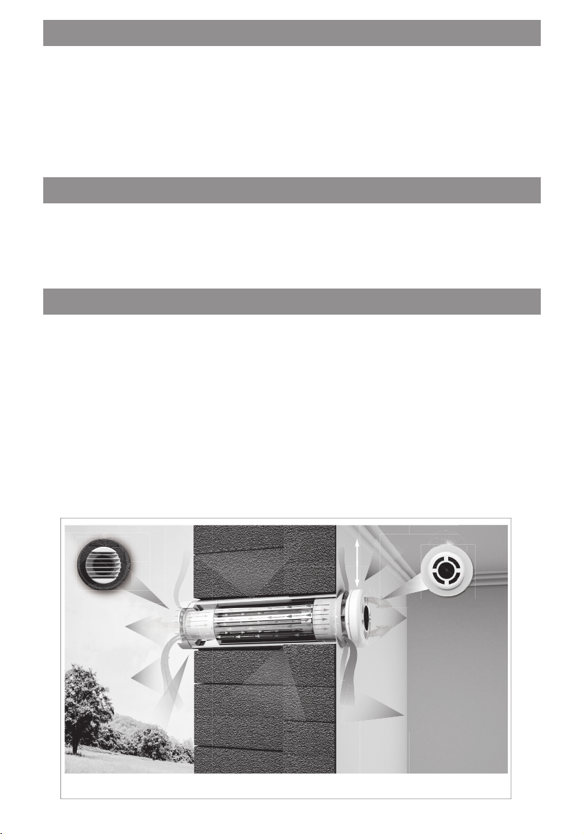
The basis of the technical solution for recuperation ventilation is the countercurrent, with a
continuous thermal cycle, a copper heat exchanger, which makes it possible to form two
different-directed airflows in the volume of one cylinder (Fig. 1).
Warm exhaust air that is removed from the room, passing through a copper heat exchanger
transmits its warmth to the counter stream of fresh air from the outside.
The system allows recover heat, which contributes to increasing the overall recuperation
rate and allows maintain the optimum humidity mode in the room. Taking into account that
air streams are separated and regulated at levels “inflow” – “exhaust”», there is no mixing of
different-directional air flows.
High velocity of the flow with sufficient heat transfer efficiency ensures removal of up to
90% moisture in a dispersed state, preventing its condensation and freezing of the heat
exchanger at low ambient temperatures.
DESCRIPTION OF THE DEVICE
Ventilation units “PRANA-150”, “PRANA-200C”, “PRANA-200G” are intended for creation and
maintenance of healthy microclimate in premises.
These systems are recommended for use in residential and public facilities (apartments,
houses, office premises, educational establishments, kindergartens, etc.).
PRANA-150 and PRANA-200G belong to the category of innovative and reliable ducts
aimed at creating and maintaining a healthy microclimate in premises of various functional
purposes.
High energy efficiency and significant air exchange capabilities make it possible to apply
these ventilation units for organizing domestic ventilation.
Technologically, the system is a monoblock with high-efficiency counter-current copper
recuperator ready to use in accordance with the design and assembly tasks and conditions.
Fig.1. The principle of work of recuperator PRANA-150, PRANA-200C, PRANA-200G

3
ADDITIONAL FUNCTIONS
“Mini heating up” function
For additional comfort in equipping residential premises with ventilation units PRANA of
residential-and-public and semi-industrial series, the function of air “Mini heating up” is
provided for. It can be switched on by pressing the “Mini heating up” button on the remote
control or in a mobile application (see the remote control manual included in the list of
standard equipment).
After having activated the function of “Mini heating up”, the temperature of the infl ow air
increases by 3-5 ºC.
When the motors are switched off and the cover of the recuperator is open, this function
additionally plays the role of an air heat curtain.
WARNING! DO NOT SWITCH ON “Mini heating up” , if the outside air temperature is +20 ºС
and above!
Function “Winter Mode”
Function “Winter Mode” is intended to prevent the icing of condensate drainage during the
cold season or to freeze it if icing has occurred.
WARNING! To avoid icing and to ensure the system operates correctly at the minus
temperature from the outside - the use of the Winter Mode is mandatory.
TECHNICAL DATA
Power supply: AC: 230 ± 10% V. Class of insulation: II. Degree of protection: IP 24.
Control: remote control, mobile application.
The body of the system is thermally insulated. Double protection against frontal blasting.
The function of “heating with minimally-raised temperature” and “freezing”.
The established service life of the system: 10 years. The warranty period: 2 years.
The use of the system is designed for long-term operation at air temperature in the range
from -30 ºС to +50 ºС.
PRANA 150 PRANA 200G PRANA 200C
Diameter of the working module, mm
with thermal insulation, mm
150
160 200
210 200
210
Diameter of the mounting hole, mm
Length of the working module, mm
≥162
≥450
≥215
≥440
≥215
≥500
Recommended area of the premises, m 2 <60 <60 <120
Amounts of air exchange during recovery, m3/h;
(the infl ow and exhaust work simultaneously):
- i n fl o w
-exhaust
-night / minimal
-passive mode
105
97
12
6
108
100
12
10
185
177
21
10
Energy consumption, W * h:
recuperator
“mini-after-heating” 4-17
51 4-17
51 4-35
56
Recovery effi ciency, % 95 96 93
Acoustic pressure from the product at a distance,
dB (A):
3m
1m 14/52 13/50 15/54
Weight of the system in individual packing ≥ 4,3 ≥ 5,8 ≥ 6,0
The size of the packing box, mm (LxHxW) ≥750х210х210 ≥750х260х260 ≥750х260х260
4
In mode «AUTO» after engine shutdown, «Winter mode» will work for 30 minutes to prevent
icing in the system, which may result in reduced effi ciency or condensate drainage
complications.
Preheating element (additional option)
Recuperators that will be used in rooms with excessive humidity in the cold climate are
recommended to be equipped with an additional heating element.
Passive mode
The operating mode of the ventilation system with the open lid of the recuperator and
switched off motors. It lies in the movement of uncontrolled airfl ows through the recuperator
due to the difference in pressure and temperature inside and outside the premises. It is
allowed to use, when the difference between outside and inside temperatures is no more
than 5 o C.
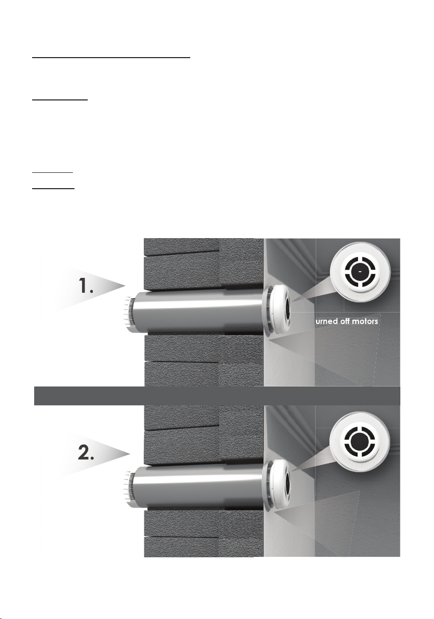
Defrosting
WARNING! In the cold season, the imper operation of the recuperator is likely to freeze it!
When freezing, it is necessary to activate function «mini-heating up» with engine switched
off for at least 60 minutes, and let it unfreeze, then turn on the recuperator to the required
mode.
turned off motors
+
the “Mini heating up”
turned on
turn on
the desired mode
1.
2.
2.
9
turned off motors
turned off motors
Fig. 2. Defrosting
5
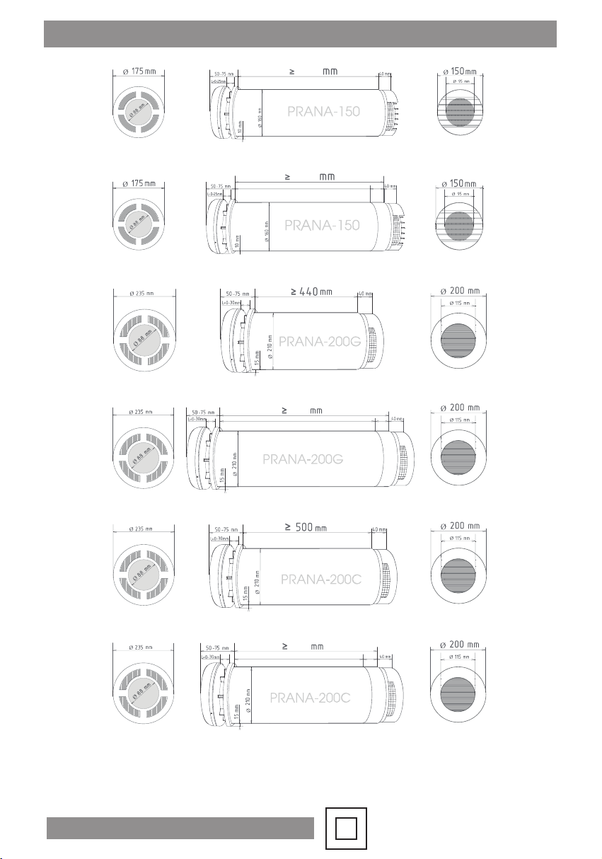
OVERALL DIMENSIONS
Class II or double insulated electrical appliance
Fig. 3. The overall dimensions and the dimensions of ventilation units “PRANA-150”,
“PRANA-200G”, “PRANA-200C”:
a) the ventilation grid and air intake in the premises;
b) monoblock, side view;
c) the ventilation grid and air intake from the outside.
475
a) c)
490
45
m
m
445 mm
a) c)
a) c)
520
45 mm
475
m
m
a) c)
a) c)
a)
b)
b)
b)
b)
b)
b) c)
45
mm
5
1
0
465
m
m
6
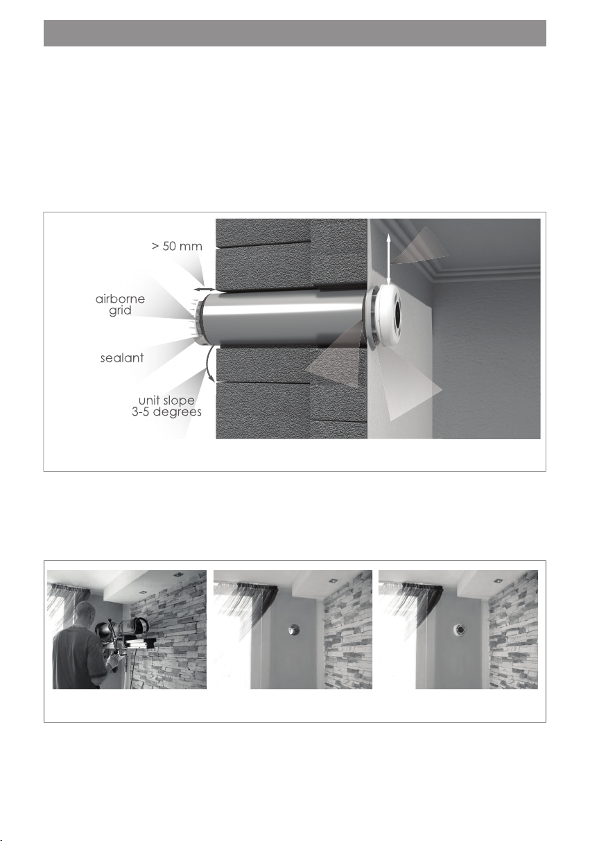
Bidirectional ventilation unit with heat recovery “PRANA” is a monoblock ready for use in
accordance with design and assembly tasks and conditions.
The system is mounted in a hole of the appriate diameter in the upper part of the wall
adjoining the outside, at a distance of no less than 100-150 mm from the ceiling or walls. The
through hole should be a slope of 3-5 degrees towards the outside. The operating module of
the ventilation unit is mounted in the hole using a seal (Fig. 4).
The length of the working module should correspond to the thickness of the wall in which
the installation will be carried out. In order to ensure the normal operation of the system, it
is necessary that its body facing the the outside extends beyond the wall by 1-2 cm to the
beginning of the air intake (Fig. 4).
INSTALATION
Fig. 4. The diagram of installing the recuperator in the wall.
airborne
airborne
grid
grid
> 50 mm
> 50 mm
unit slope
unit slope
3-5 degrees
3-5 degrees
unit slope
3-5 degrees
unit slope
unit slope
3-5 degrees
unit slope
100-150 mm
from the ceiling
sealant
sealant
sealant
air intake
Fig. 5. An example of mounting of the recuperator “PRANA-150”, “PRANA-200G”, “PRANA-200C”.
Other preparatory works:
- preparation of the hole for installing the switch and preparation of the grooves for the
installation of the electrical supply network between the system, the switch and the place of
connection of the system to the power supply source.

7
IMPORTANT:
READ THESE INSTRUCTIONS BEFORE COMMENCING THE INSTALLATION
DO NOT install this duct in areas where the following may be present or occur:
- Excessive oil or a grease laden atmosphere.
- Corrosive or fl ammable gases, liquids or vapors.
- Ambient temperatures higher than 40°C or less than –5°C.
- Possible obstructions which would hinder the access or removal of the recuperator.
SAFETY AND GUIDANCE NOTES
A. All wiring to be in accordance with the current I.E.E. Regulations, or the appriate
standards of your country and MUST be installed by a suitably qualifi ed person.
B. The recuperator should be vided with a local isolator switch capable of disconnecting
all poles, having a contact separation of at least 3mm.
C. Ensure that the mains supply (Voltage, Frequency, and Phase) complies with the rating
label.
D. The recuperator should only be used in conjunction with fi xed wiring.
E. The recuperator should not be used where it is liable to be subject to direct water spray
for longed periods of time.
F. Stationary appliances not fi tted with means for disconnection from the supply mains
having a contact separation in all poles that vide full disconnection under over voltage
category III, the instructions state that means for disconnection must be incorporated in the
fi xed wiring in accordance with the wiring rules.
Connecting the recuperator, controlling the system from the remote control.
The recuperator MUST be isolated from the power supply during the installation/or
maintenance
Fig. 6
220-240V
~50Hz
CONNECTING TO THE ELECTRICAL SUPPLY NETWORK
3Amp max
N
L
WARNING! Ensure that the electric power supply is really switched off using appriate test
equipment!
- To connect ventilation unit, follow wiring diagram Figure 6
- The ventilation unit should only be used in conjunction with fi xed wiring
- All electrical cables used in the installation should have the cross-section of 0.5-0.75
mm². The operation of the system is controlled using a remote control or mobile application
that controls the operation of the fans installed in the body of the ventilation system (it turns
on, regulates and turns off).
- Cable entry can only be made from the rear of the unit. Shorten the electric cable,
if necessary, to a length that is convenient for electrical connection.
- The ventilation unit is suitable for connection to 220-240V 50 Hz supply
- The ventilation unit is class II double insulated duct and must not be earthed
The PRANA 150 / 200G / 200C recuperators are adapted to connected voltage in an
automatic mode, without the use of software. This significantly reduces the noise indicators of
the equipment and allows ensure the noise characteristics of the ventilation system declared
in the technical passport.
Class II or double insulated electrical appliance

8
START-UP
The first start-up of the device should be carried out by a specialist who has theoretical
knowledge and has practical skills in the electrical installation of this ventilation unit.
Before starting-up, it is necessary to check:
- all connections have been made correctly and ensure all terminal connections are securely
fastened (according to Fig. 6);
- if the air in is open and impeller rotates and is free from obstructions ;
- if the ventilation unit is functioning perly.
WARNING! Before turn on the device, open the air intake as indicated in the photo below:
OPERATION
During operation, it is necessary to periodically check:
- the quality of function of the fans;
- the correspondence of the graphic symbols of the indication;
- correct operation of the device in accordance with the control devices.
The device must be turned off in case of:
- excessive oscillations and noise;
- damage to the elements of the device body;
- damage to the insulation of the electric cable;
- damage to the elements of automation;
- the temperature of the outside air is below -30 ºС.
1. The lid is closed. Do not turn on the device,
when the lid is closed.
2. Smoothly pull the cover. The device is ready
for starting-up.
The PRANA 150 / 200G / 200C recuperators are adapted to an existing electrical supply net
work automatically, without the use of software. It signifi cantly reduces the noise indicators
of the equipment and allows ensure the noise characteristics of the ventilation unit declared
in the technical passport.
ADAPTATION TO THE ELECTRICAL SUPPLY NETWORK
9
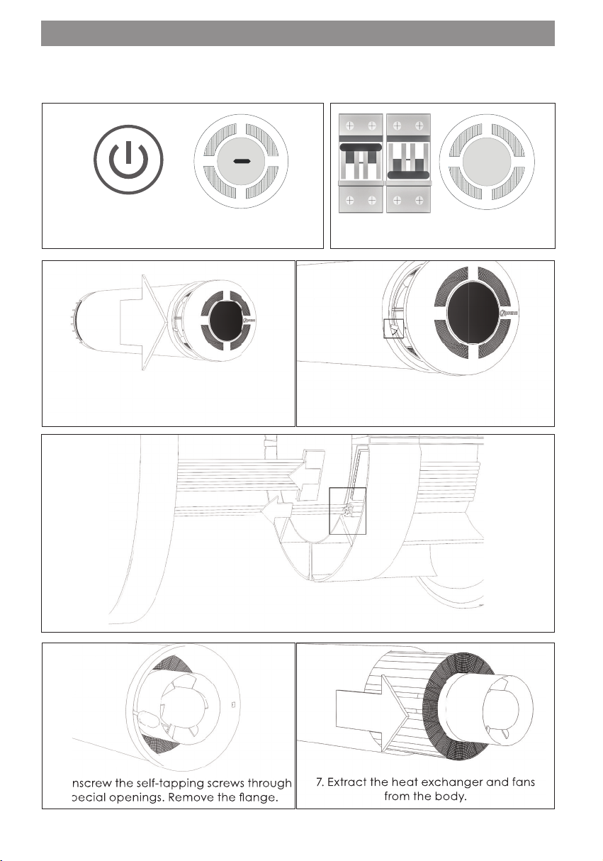
1. Press the “Turn off” button on the remote
control. Turn off the ventilation unit. 2. De-energize the device.
7. Extract the heat exchanger and fans
from the body.
6. Unscrew the self-tapping screws through
special openings. Remove the fl ange.
MAINTENANCE
The maintenance consists in periodic (recommended 1-2 times a year) and preventive
inspection of surfaces of the fans and the heat exchanger and, if necessary, in cleaning
them. The cedure for disassembling / assembling the device for / after cleaning:
6. Unscrew the self-tapping screws through
special openings. Remove the fl ange.
7. Extract the heat exchanger and fans
from the body.
3. Open the lid of the recuperator. 4. Turn the fasteners of the lid and remove it.
5. Disconnect the cable and remove the power wires by
pressing the terminals. Remove the lid.
10
ASSEMBLY IN THE REVERSE ORDER
The technological cess vides for 100% inbound quality control for all components, as well
as double 100% inbound control after their manufacture and 24-hour run in the maximum
performance mode.
Transportation and storage of the ducts in individual packing boxes is ensured in a horizontal
position.
Keep the recuperator in the factory packaging under the cover or (in enclosed space) with
relative humidity of air of no more than 70% and air temperature from -20˚С to + 40˚С.
TRANSPORTATION AND STORAGE RULES
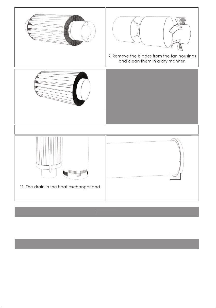
11. The drain in the heat exchanger and
the body must coincide and be below
during the installation.
12. The fl ange must be installed correctly;
the larger trusion of the should be below.
10. Clean the heat exchanger in adry or, if
necessary, in a wet manner.
WARNING!
Before rinsing or wet cleaning of the
heat exchanger, make sure that all
the electrical components and parts
are removed from the heat exchanger
(except for the components of
“Mini heating up” and «heating the
condensate drainage».
QUALITY
9. Remove the blades from the fan housings
and clean them in a dry manner.
11. The drain in the heat exchanger and
>
9. Remove the blades from the fan housings
and clean them in a dry manner.
8. Unscrew the self-tapping screws.
Remove the fans on both sides.

11
- Ventilation unit.
- Technical - operation documentation.
- Technical (warranty) card.
- Remote control.
- Manual for the remote control.
- Packing box
SCOPE OF DELIVERY
SAFETY REQUIREMENT
All electrical installation works (maintenance) must be carried out only by a qualifi ed
specialist with a category of admission to such works.
Ensure that during installation, the visions, mechanical and electrical installation rules and
norms valid in the country, in which the installation is carried out, are observed.
WARNING! All installation and electrical works relating to the connection (maintenance) are
carried out only after the device is disconnected from the electrical supply network.
WARNING! Do not operate the ventilation unit, if there is a threat that foreign objects may
enter the infl ow part of the body, which objects may jam or damage the impeller of any of
the two fans.
WARNING! Do not operate the ventilation unit in premises, where the air contains aggressive
substances and does not correspond to the working temperature regime.
After commissioning, the ventilation unit must comply with the visions of the following
directives:
- Directive 2014/35 / EU. Low Voltage Directive (LVD);
- Directive 2006/42 / EU. Safety of Machinery mechanisms;
- Directive 2004/108 / EU. Electromagnetic Compatibility (EMC);
- Directive 2011/65 / EU. Restriction of Hazardous Substances (RoHS);
- Directive 2009/128 / EU. Ecodesign (ErP);

12
Other manuals for 150
1
This manual suits for next models
11
Table of contents
Other prana Air Conditioner manuals


