Pratissoli KT24A Operating instructions

KT24A/28A/30A/32A/36A/40A
Repair Manual
General Pump is a
member of the
Interpump Group
8
Ref 300943 Rev.A
03-14
KT24A, KT28A, KT30A, KT32A, KT36A, KT40A

GENERAL PUMP A member of the Interpump Group
KT24A/28A/30A/32A/36A/40A SERIES
Page 2
INDEX
1. INTR DUCTI N . . . . . . . . . . . . . . . . . . . . . . . . . . . . . . . . . . . . . . . . . . . . . . . . . .Page 3
2. REPAIR INSTRUCTI NS . . . . . . . . . . . . . . . . . . . . . . . . . . . . . . . . . . . . . . . . . . .Page 3
2.1 Repairing Mechanical Parts . . . . . . . . . . . . . . . . . . . . . . . . . . . . . . . . . . . . . . .Page 3
2.1.1 Disassembly of Mechanical Parts . . . . . . . . . . . . . . . . . . . . . . . . . . . .Page 4
2.1.2 Reassembly of Mechanical Parts . . . . . . . . . . . . . . . . . . . . . . . . . . . .Page 6
2.1.3 Increase and Reduction Classes . . . . . . . . . . . . . . . . . . . . . . . . . . . .Page 8
2.1.4 Disassembly / Reassembly of Bearings and Shims . . . . . . . . . . . . . .Page 8
2.2 Repairing Hydraulic Parts . . . . . . . . . . . . . . . . . . . . . . . . . . . . . . . . . . . . . . . . .Page 11
2.2.1 Dismantling the Head-Valve Units . . . . . . . . . . . . . . . . . . . . . . . . . . .Page 11
2.2.2 Reassembling the Head-Valve Units . . . . . . . . . . . . . . . . . . . . . . . . .Page 14
2.2.3 Dismantling the Head-Seals . . . . . . . . . . . . . . . . . . . . . . . . . . . . . . . .Page 15
2.2.4 Dismantling the Piston Unit . . . . . . . . . . . . . . . . . . . . . . . . . . . . . . . . .Page 17
2.2.4 Assembling the Head - Seals - Piston Unit . . . . . . . . . . . . . . . . . . . . .Page 18
3. SCREW CALIBRATI N . . . . . . . . . . . . . . . . . . . . . . . . . . . . . . . . . . . . . . . . . . . . .Page 19
4. REPLACING THE C N-R D F T BUSHINGS . . . . . . . . . . . . . . . . . . . . . . . . .Page 20
5. REPAIR T LS . . . . . . . . . . . . . . . . . . . . . . . . . . . . . . . . . . . . . . . . . . . . . . . . . . .Page 21
6. MAINTENANCE L G . . . . . . . . . . . . . . . . . . . . . . . . . . . . . . . . . . . . . . . . . . . . . .Page 22
Ref 300943 Rev.A
03-14

1. INTR DUCTI N
This manual describes the instructions for repairing KT Series pumps, and must be carefully read and
understood before performing any repair intervention on the pump. Proper pump operation and longevity
depend on the correct use and maintenance. General Pump declines any responsibility for
damage caused by the misuse or the non-observance of the instructions described in this manual.
2. REPAIR INSTRUCTI NS
2.1 Repairing Mechanical Parts
Mechanical parts repair must be performed after removal of oil from the casing. To drain
the oil, remove the oil dipstick, (1, fig. 1) and then the draining plug (2, fig. 1).
The oil must be placed in a suitable container and disposed of in special centers.
It absolutely must not be discarded into the environment.
GENERAL PUMP A member of the Interpump Group
KT24A/28A/30A/32A/36A/40A SERIES
Page 3
Ref 300943 Rev.A
03-14

GENERAL PUMP A member of the Interpump Group
KT24A/28A/30A/32A/36A/40A SERIES
Page 4
2.1.1 Disassembly of Mechanical Parts
The operations described must be performed after removing the hydraulic part, ceramic pistons and
splash guards from the pump (paragraphs 2.2.3, 2.2.4).
Remove in the following order:
• The pump shaft tab
• The rear cover
• The connecting rod cap as follows:
unscrew the cap fixing screws, remove the con-rod caps with their lower half-bearings (fig. 2)
paying atention to the numbered sequence during disassembly.
To avoid possible errors, caps and con-ro shanks have been numbered on one side (1, fig. 2/a).
- Push the piston guides forward with their con-rods to facilitate side extraction of the pump as
indicated in fig. 4.
Ref 300943 Rev.A
03-14
- The side covers using - for extraction 3 fully threaed M6 x 50 screws, inserting them in the
threaded holes as indicated in fig. 3

GENERAL PUMP A member of the Interpump Group
KT24A/28A/30A/32A/36A/40A SERIES
Page 5
• Remove the pump shaft
• Complete the disassembly of the con-rod units by removing them from the pump casing and
removing the piston guide pins
• Remove the pump shaft seal rings using common tools
• Remove the piston guide seal rings as described below:
Use the extractor, p/n F26019400 (1, fig. 5) and the gripper, p/n F27503800 (2, fig. 5). Insert the gripper as
far as possible onto the seal ring with the aid of a hammer (fig. 5/a), subsequently screwing the extractor to
the gripper, and use the extractor hammer (fig. 5/b) until the ring to be replaced is removed (fig. 5/c).
Ref 300943 Rev.A
03-14

GENERAL PUMP A member of the Interpump Group
KT24A/28A/30A/32A/36A/40A SERIES
Page 6
2.1.2 Reassembly of mechanical parts
• Insert the piston/con-rod guide units into the pump casing, directing the numbering on the con-rod
shank towards the top of the casing.
To facilitate pump chaft insertion (without the tab), it is essential to repeat the operation performed during
disassembly, pushing the piston/con-rod guide units as far down as possible (paragraph 2.1.1).
• Before assembling the side cover on the PTO side, check the conditions of the radial ring lip seal
and relative contact area on the shaft.
Make sure that the reference marks on the upper half-bearing (1, fig. 6) and lower half-
bearings (2, fig. 6/a) are positioned in their respective seats in the con-rod and cap.
After having checked that the casing is clean, proceed with assembly of the mechanical part as described
below:
• Assemble the upper and lower half-bearings in their seats in the con-rods and caps.
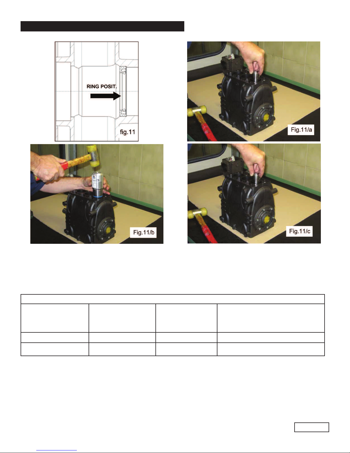
If replacement is necessary, position the new ring using tool p/n F27904500 as incicated in fig. 7
If the pump shaft shows diametrical wear in the area of contact with the lip seal, in order to
prevent the grinding operation, it is possible to reposition the ring in abutment with the cover
as shown in fig. 7.
Before assembling the side covers, make sure there are O-rings on both of them and shim rings on
the indicator side cover only. To facilitate filling of the first section and relative insertion of the covers on
the casing, we recommend using three partially threaded M6x40 screws (1, fig. 8), then completing the
operation with the screws supplied (M6x16).
Ref 300943 Rev.A
03-14
GENERAL PUMP A member of the Interpump Group
KT24A/28A/30A/32A/36A/40A SERIES
Page 7
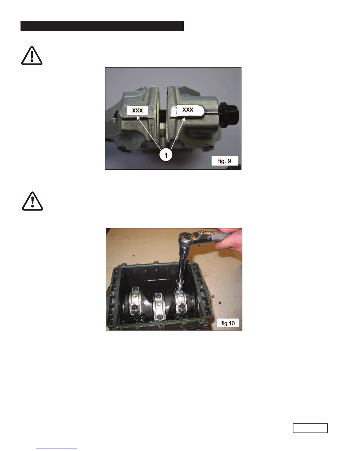
Fasten the caps to their respective con-rod shanks by means of M8x1x42 screws (fig. 10) lubricating both the
underhead and the threaded shank, proceeding in two stages:
• Couple the con-rod caps to their shanks, referring to the numbering (1, fig. 9).
Note the correct assembly direction of the caps.
1. Manually turn the screws until they begin to tighten
2. Tightening torque: 22 Ft. Lbs. (30 Nm)
Alternatively, ensure:
1. Pre-tightening torque: 7-11 Ft. Lbs. (10-15 Nm)
2. Tightening torque: 22 Ft. Lbs. (30 Nm)
Ref 300943 Rev.A
03-14
• After having completed tightening operations, check that the con-rod head has a side clearance in
both directions.
• Assemble the new piston guide seal ring with the relative seats on the pump casing (fig. 11)
following the procedure described:
Using tool p/n F27904200 composed of a tapered bushing and a buffer, screw the tapered bushing into the
hole in the piston guide (fig. 11a), insert the new seal ring on the buffer as far as it will go (determined by
the height of the buffer) into its seat on the pump casing (fig. 11b), remove the tapered bushing (fig. 11/c).
GENERAL PUMP A member of the Interpump Group
KT24A/28A/30A/32A/36A/40A SERIES
Page 8
Ref 300943 Rev.A
03-14
• Mount the rear cover complete with the O-ring, positioning the dipstick hole upward.
• Insert Oil in the casing as indicated in the use and maintenance manual.
2.1.3 Reduction Classes
TABLE F REDUCTI NS F R CRANKSHAFTS AND C N-R D HALF-BEARINGS
Recovery Classes
(mm)
Part Number
Half-bearing
Upper
Part Number
Half-bearing
Lower
Correction on the Shaft Pin
Diameter
(mm)
0.25 F90922100 F90922400 Ø39.75 0/-0.02 Ra 0.4 Rt 3.5
0.50 F90922200 F90922500 Ø39.50 0/-0.02 Ra 0.4 Rt 3.5
2.1.4 Disassembly/Reassembly of Bearing and Shims
The type of bearings (taper roller) ensures the absence of axial clearance on the crankshaft. The shims are
defined to meet this necessity. For disassembly-reassembly and for any replacements, carefully observe the
following directions:
GENERAL PUMP A member of the Interpump Group
KT24A/28A/30A/32A/36A/40A SERIES
A) Disassembly/Reassembly of the crankshaft without bearings replacement
After having removed the side covers as indicated in point 2.1.1, check the conditions of the rollers and their
relative tracks. If all parts are in good condition, clean the components carefully with a degreaser and
redistribute lubricant oil uniformly. The previous shims can be reused, taking care to insert them only under
the indicator side cover.
Once the complete unit is mounted (indicator side flange and shaft and motor side flange), check that the
rotation torque of the shaft - with the con-rod disconnected - is a minimum 3 Ft. bs. (4 Nm), max. 4.5 Ft. bs
(6 Nm).
To bring the two side covers closer to the casing, it is possible to use 3 M6x40 screws for the first positioning
phase as indicated in fig. 8 and the screws provide for final fastening.
Shaft rotation torque (with the con-rod connected) should not exceed 6 Ft. b. (8 Nm).
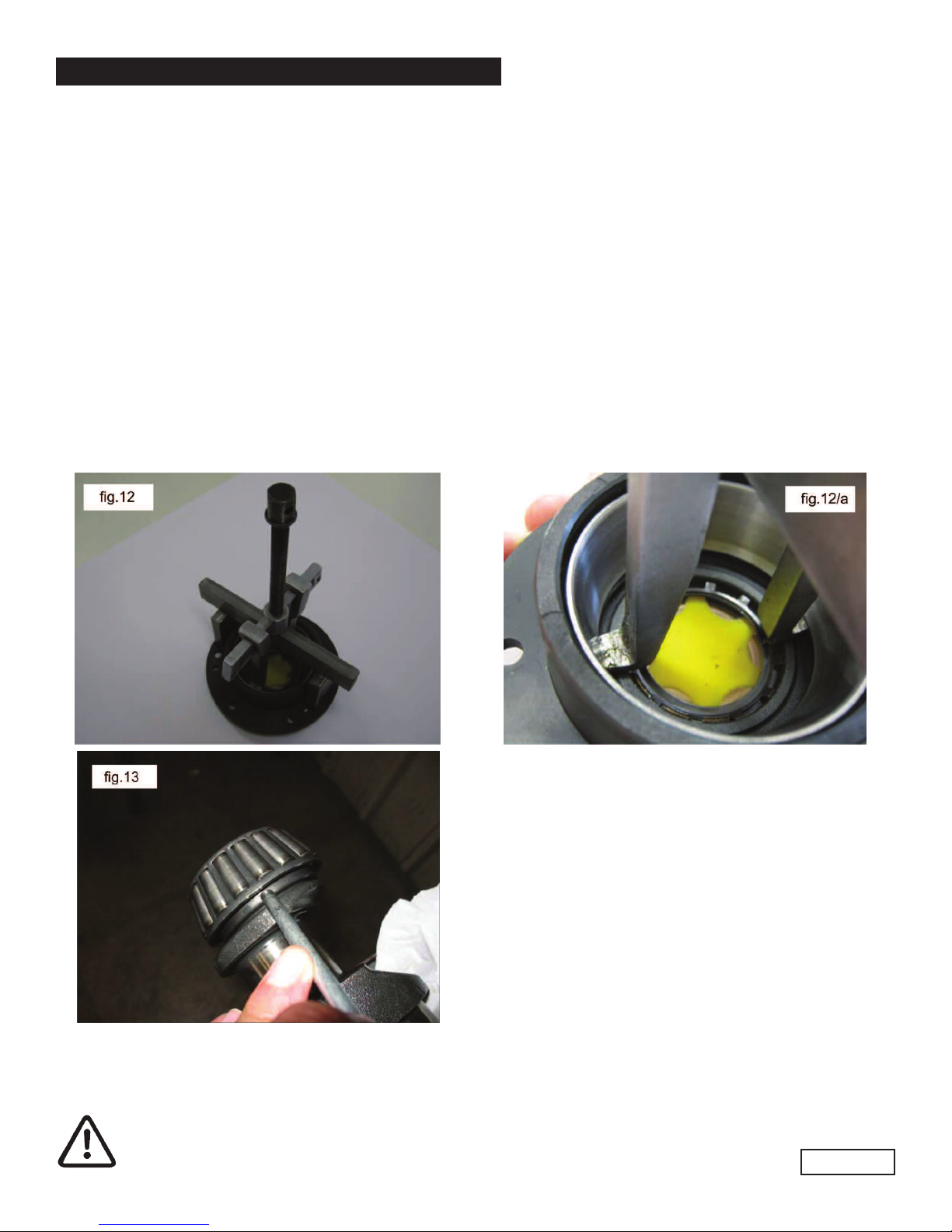
A) Disassembly/Reassembly of the crankshaft with bearings replacement
After removing the side covers, as described above, remove the outer ring nut on the bearings from its seat
on the covers, using an appropriate extractor as shown in fig. 12 and 12a.
Remove the inner ring on the bearings from the two ends of the shaft, again using an appropriate extractor
or, alternatively, a simple “pin punch” as shown in fig. 13.
The new bearings can be mounted cold with a press or rocker, supporting it on the lateral surface of the
ring nuts involved in press fitting with the rings. The press fitting operation can be facilitated by heating the
involved parts to a temperature between 250o-300oF(120o-300o C), ensuring that the ring nuts go down to
end stroke in their housings.
Never exchange the parts of the two bearings.
Page 9
Ref 300943 Rev.A
03-14

GENERAL PUMP A member of the Interpump Group
KT24A/28A/30A/32A/36A/40A SERIES
Page 10
Determining the shim pack:
Perform the operation while the piston/con-rod guide units are assembled, the con-rod caps are disconnected
and the con-rods are pushed downwards. Insert the crankshaft in the casing, checking that the PTO shank
comes out from the provided side. Secure the PTO side flange to the casing, taking care with the lip seal as
described previously and tighten the fixing screws to the recommended torque. Then feed the flange on the
indicator side without shims in the case and start to move it closer, manually screwing the M6x40 service
screws in equally, with small rotations such as to move the cover in slowly and correctly.
At the same time, check that the shaft rotates freely by turning it manually.
Continuing the procedure in this way, a sudden increase in difficulty during shaft rotation will soon be
experienced.
At this point, halt the forward movement of the cover and loosen the fixing screws completely.
With the aid of a thickness gauge, measure the clearance between the side cover and pump casing (fig. 4).
Detected
Measurement
Shim
Type # Pieces
From: 0.05 to: 0.10 / /
From: 0.11 to: 0.20 0.1 1
From: 0.21 to: 0.30 0.1 .2
From: 0.31 to: 0.35 0.25 1
From: 0.36 to: 0.45 0.35 1
From: 0.46 to: 0.55 0.35
0.10
1
1
From: 0.56 to: 0 .60 0.25 2
From: 0.61 to: 0.70 0.35
0.25
1
1
Ref 300943 Rev.A
03-14
Once the type and number of shims have been determined using the table, check the following: assemble the
shim pack on the indicator side cover centring (fig. 15), secure the cover to the casing, following the
procedure in paragraph 2.1.2 and tighten the screws to their recommended torque. Check that the shaft
rotation stall torque is between 3-4.5 Ft. bs.(4-6 Nm). If this torque is correct, connect the con-rods to the
crankshaft and to the next stages. If it is not, redefine the shim pack, repeat the operations.
Proceed to detemine the shim pack, using the table below:

GENERAL PUMP A member of the Interpump Group
KT24A/28A/30A/32A/36A/40A SERIES
Page 11
2.2 REPAIRING HYDRAULIC PARTS
2.2.1 Dismantling the Head - Valve Units
Operations are limited to inspection or replacement of valves, if necessary and, however, at the intervals
indicated in the “Preventative Maintenance” table in chapter 11 of the use and maintenance manual. The
valve units are assembled vertically inside the head.
Operate as follows to extract them:
• Unscrew the 8 M14x40 suction valve cover fastening screws and the 8 m12x35 outlet valve cover fastening
screws (fig, 16 and 16a) using the extractor hammer p/n F26019400 combined with tool F27726200 extract
• The KT24A, 28A, 30A, 32A suction and outlet valve units and KT36A or 40A inlet valve units using a
simple tool as indicated in fig. 18
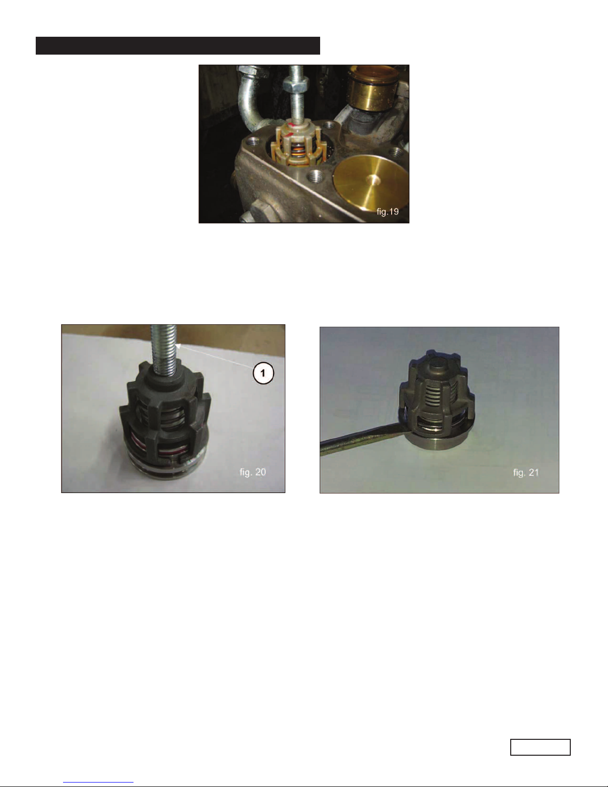
• Extract the KT36 or KT40 pump suction valve units using an extractor hammer part #F26019400 combined
with tool #F27513600 (fig. 19).
Ref 300943 Rev.A
03-14
GENERAL PUMP A member of the Interpump Group
KT24A/28A/30A/32A/36A/40A SERIES
Dismantling of the suction and outlet valve units can be carried out screwing in a sufficiently long M10 screw
which can move the valve plate and remove the valve guide from the seat (1, fig. 20). If the threaded holes
should not be present on the valve guides, dismantling can be easily carried out by leveraging with simple
tools (fig 21).
Page 12
Ref 300943 Rev.A
03-14

GENERAL PUMP A member of the Interpump Group
KT24A/28A/30A/32A/36A/40A SERIES
Page 13
Ref 300943 Rev.A
03-14
If the suction valve seats remain stuck on the head (for example scaling due to prolonged
pump activity), operate as follows:
Suction and outlet valves:
For KT24A, 28A, 30A, 32A use tools #F26019400, and F27513700 (fig. 22)
Suction valves:
For KT36A and 40A use tools #F26019400, F27516900 (fig. 22)
Outlet valves
For KT36A and 40A use tools #F26019400 and F27513700 (fig 22)
2.2.2 Reassembling the Head - Valve Units
GENERAL PUMP A member of the Interpump Group
KT24A/28A/30A/32A/36A/40A SERIES
Page 14
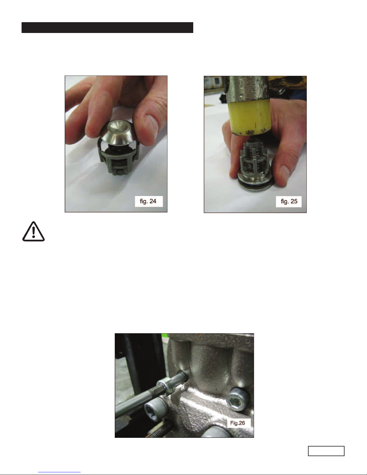
Pay particular attention to the conditions of the various components and replace if necessary, and at
the intervals indicated in the “Preventative Maintenance” table in chapter 11 of the use and
maintenance manual. At every valve inspection, replace all O-rings and all anti-extrusion rings both
in the valve groups and on the valve plugs.
Before repositioning the valve unit, thoroughly clean and dry the relative seats in the head as
indicated in fig. 25.
Ref 300943 Rev.A
03-14
GENERAL PUMP A member of the Interpump Group
KT24A/28A/30A/32A/36A/40A SERIES
Page 15
Ref 300943 Rev.A
03-14
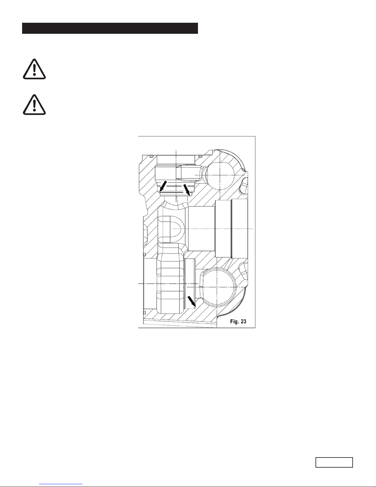
To reassemble the various components, follow the reverse operations listed above as described in point
2.2.1. Reassemble the valve unit (fig. 24) to facilitate insertion of the valve guide in the seat, use a hammer,
acting on the whole circumference (fig. 25).
Insert the suction and outlet valve units, checking that they are down to end stroke in the
head housing. Then apply the valve covers and calibrate the respective M14x40 screws
(suction valve covers) and M12x35 (outlet valve cover) screws. For the values of the torques
and tightening sequences follow the instructions in chapter 3.
2.2.3 Dismantling the Head - Seals
Replacement of the seals is necessary from the moment you begin to detect water leaks from the
drainage holes provided on the back of the pump casing, and at the intervals indicated in the
Preventative Maintenance” table in chapter 11 of the use and maintenance manual.
A) Unscrew the M10x110 head fixing screw as indicated in fig. 26.
GENERAL PUMP A member of the Interpump Group
KT24A/28A/30A/32A/36A/40A SERIES
Page 16
Ref 300943 Rev.A
03-14
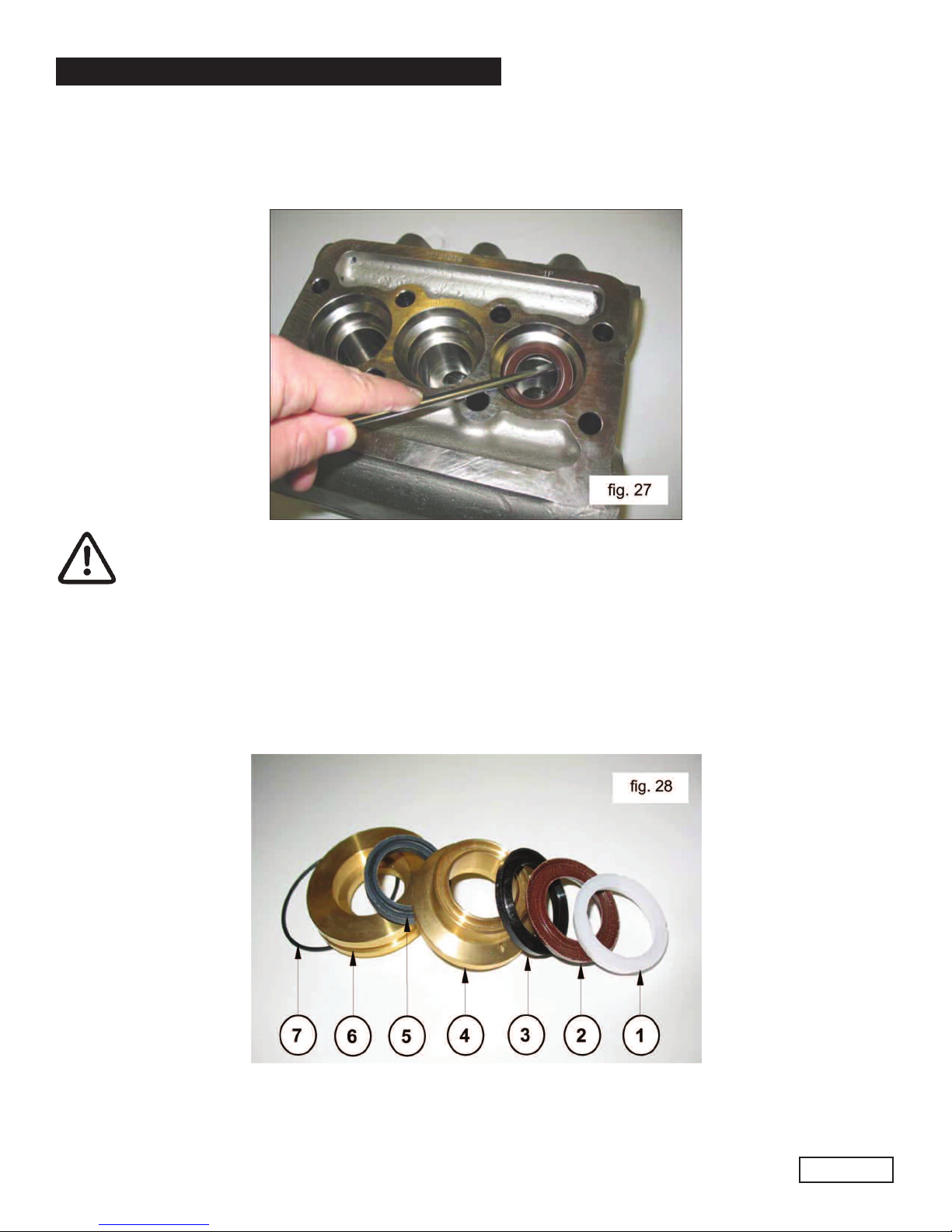
B) Separate the head from the pump casing.
C) Extract the high pressure seals from the head and the low pressure ones from the support, using
simple tools as indicated in fig. 27, being careful not to damage the respective housings.
Pay attention to the order of seal pack disassembly as indicated in fig. 28 composed of:
1. Head ring
2. HP seal
3. Restop ring
4. Seals support
5. P seal
6. Seal ring
7. O-ring

GENERAL PUMP A member of the Interpump Group
KT24A/28A/30A/32A/36A/40A SERIES
Page 17
Check and verify their conditions, replace if necessary
At every disassembly all o-rings on the piston unit must be replaced.
Ref 300943 Rev.A
03-14
2.2.4 Dismantling the Piston Unit
The piston unit does not require any routine maintenance. Maintenance is limited to visual checks only. To
extract piston units: loosen the M7x1 piston fixing screws as indicated in fig. 29.

GENERAL PUMP A member of the Interpump Group
KT24A/28A/30A/32A/36A/40A SERIES
Page 18
2.2.5 Reassembling the Head - Seals - Piston Unit
To reassemble the various components, follow the reverse operations listed above as described in pint 2.2.3,
taking particular care:
A) Seals pack Respect the same order used during disassembly operations.
B) ubricate components 2,3 and 5 with OCI IS silicone grease p/n F12001600; this operation is also
deemed necessary to facilitate adjustment of the lip seal on the piston.
C) For correct assembly of HP seals in their housing on the head without causing any damage to lip seals,
use suitable tools according to the pump diameters as indicated in chapter 4.
D) Replace the piston, tightening the screws with a torque wrench, respecting the tightening torque values
ad indicate in chapter 3.
E) Replace the head as follows:
1. Position the seal support in the respective seats on the casing.
2. Using two screws - p/n F27726000, fasten the casing as indicated in fig. 30. Position the complete
head, making sure that it is centered only on the central piston.
3. Complete the operations, following the tightening procedure. For the values of the torques and
tightening sequences follow the instructions in chapter 3.
Ref 300943 Rev.A
03-14
GENERAL PUMP A member of the Interpump Group
KT24A/28A/30A/32A/36A/40A SERIES
3. SCREW CALIBRATI N
Screws are to be fastened exclusively using a torque wrench.
Description
Exploded View
Position
(From wner’s Manual)
Fastening
Ft. Lbs.
Fastening
Nm
Cover Fixing Screw 9 7.4 10
Oil Discharge Plug 11 30 40
Piston Fixing Screw 27 14.8 20
Con-rod Fixing Screw 18 22.1* 30*
Valve Cover Fixing Screw Outlet 58 132.8*** 180***
Valve Cover Fixing Screw Suction 45 88.5*** 120***
Head Fixing Screw 55 30** 40**
2nd PTO Flange Fixing Screw 96 107**** 145****
* The con-rod cap fixing screws must be tightened at the same time respecting the
phases indicated on page 7.
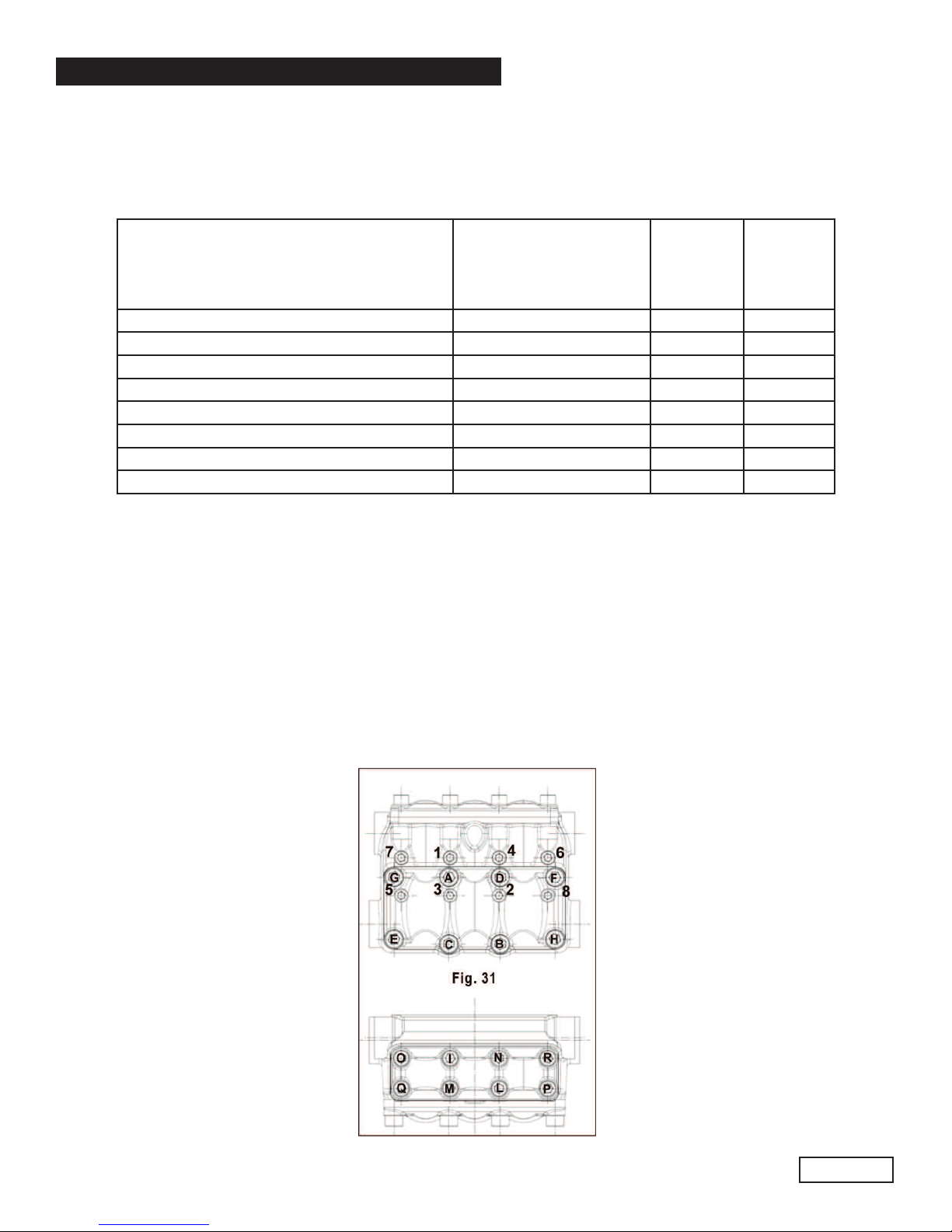
** The head fixing screws (exploded position 55) must be tightened with a torque wrench respecting
the sequence shown in the diagram in fig. 31.
*** The valve cover fixing screws (exploded position 45 must be tightened with a torqe wrench
respecting the order shown in the iagram in fig. 31.
****To fix the 2nd PTO flange, use octite 243 blue, p/n F12006400.
Page 19
Ref 300943 Rev.A
03-14

GENERAL PUMP A member of the Interpump Group
KT24A/28A/30A/32A/36A/40A SERIES
Page 20
Ref 300943 Rev.A
03-14
4. REPLACING THE C N-R D F T BUSHING
During maintenance, if it becomes necessary to replace the con-rod foot bushing, proceed as follows:
When removing the worn bushing, take great care not to damage or scratch the seat on
the con-rod.
Perform cold press fitting of the new bushing. During the operation, ensure that:
• the lubrication hole coincides with the corresponding hole on the con rod;
• the cutting junction is directed as shown in fig. 32.
Then perform mechanical processing. The dimensions and tolerances shown in fig. 32 MUST
be respected.
This manual suits for next models
10
Table of contents
Popular Power Pump manuals by other brands

EHEIM
EHEIM 1250 instructions

Greenlee
Greenlee 940m3 SERIES Operation, service and parts instruction manual

Stuart
Stuart Boostamatic 4000 operating instructions

Yard Works
Yard Works YW20PTP instruction manual

Wacker Neuson
Wacker Neuson PT 3H Operator's manual

BLACKMER
BLACKMER ProVane PV6B Installation, operation and maintenance instructions


