PRD 700 User manual

PRD 700
PRD 700 Boost controller w/ Can Bus interface
Technical Details
Voltage: 8-18 V DC
Operating Temperature: -10 to +60 C
Dimensions: w 81mm, h 49mm, 12mm
Aluminum construction
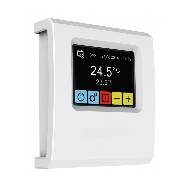
Display.2.4″ TFT Intelligent LCD Touch Display in aluminum framing
4Bar MAP sensor
Solenoi valve
Weight: 62 g
Features
7 control mo es (Off-Low-High-RPM1-RPM2-VSS-GEAR)
Boost by RPM (configurable 2D Map)
Boost by VSS (configurable 2D Map)
Boost per GEAR
Can-Bus integration (Timing A vance, TPS, CWT, IAT etc)
Configurable shift light
Exhaust Gas Temperature (K-Type)
Failsafe settings (boost cut & warning for AFR , Boost or EGT limits)
Failsafe setting (boost cut &warning for WMI)
RPM Duty A (4Dmap)
DTC Fault clearing
(Un er Dev.) Programmable Aux failsafe input to limit boost un er con itions (for example when
nitrous switch is activate or when there is no voltage from methanol controller etc.)
(Un er Dev.) Logging using our purpose-built Win ows application to monitor & plot real time
values like Actual uty cycle, spark a vance, boost pressure etc
(Un er Dev.) VAG Group can bus mo e (i.e. Timing retar ation per cylin er etc)
Prd.com.gr - PRD 700 Manual page 1

PRD 700
Table of Contents
Important Information..........................................................................................................................3
Settings.................................................................................................................................................6
1. Mode ……………………………………………………………………………………….6-7
2. PWM Fre uency........................................................................................................................8
3. Initial pressure...........................................................................................................................9
4. Boost warning.........................................................................................................................10
5. D.boost.w.................................................................................................................................11
6. LOW set..................................................................................................................................12
7. HIGH set..................................................................................................................................13
8. EGT WARNING.....................................................................................................................14
9. RPM Multiplier …………………………………………………………………………… 15
10. RPM preset 1..................................................................................................................16-17
11. RPM preset 2..................................................................................................................17-18
12. VSS preset......................................................................................................................18-19
13. GEAR preset........................................................................................................................20
14. GEAR ratio calibration........................................................................................................21
15. VSS multiplier (VSS)..........................................................................................................22
16. RPM Duty Add ………………..………………………………………………………….23
17. AFR Warning.......................................................................................................................24
18. AFR Pressure.......................................................................................................................25
19. AFR Duty %........................................................................................................................26
2 0. AFR Rpm.............................................................................................................................27
21. Shift light.............................................................................................................................28
22 . MAX rec MAP....................................................................................................................29
23. AFR CANBUS 0=NO 1=YES............................................................................................30
24. Reverse Leds ……………………………………………………………………………..31
25. CANBUS read delay [ms]...................................................................................................32
26. USE CANBUS 0=NO 1=YES.............................................................................................33
27. FIRMWARE MODE...........................................................................................................33
28. AUX IN 1=N 2=R ………………………………………………………………………...34
29. WMI ENABLED ………………………………………………………………………….35
30. WMI START PRES. ………………………………………………………………………36
31. WMI MAX PRES. ………………………………………………………………………..37
32. WMI PRESET 1 …………………………………………………………………………..38
33. CHEAT BOOST (TM) …………………………………………………………………….39
34. ENABLE CHEAT(TM) …………………………………………………………………..40
Prd.com.gr - PRD 700 Manual page 2

PRD 700
3 5. Restore to default settings....................................................................................................41
Installation Instructions......................................................................................................42-43-44-45
Wiring Plan.................................................................................................................42-43
Connections...............................................................................................................................44-45
Important Information
Please read the following manual carefully. Proceed to the installation process IF and
ONLY you completely understand notifications titled as “Important”, “Warning”,
“Attention”.
Important
This product must be installed ONLY while the engine is off.
This product is ONLY for vehicles with 12V battery system.
Prior to installation, all necessary safety measures such as removal of the
negative terminal should be taken.
Warning
1. Installation and regulation of this product must be done only by a trained
expert, if not it may damage the unit and the vehicle.
2. While installing the product to the vehicle, make sure that the unit does not
interfere with the driver’s view and the smooth vehicle operation.
3. Before soldering and using other tools of installation, make sure that you read
and understood their manuals. Wrong use may cause injuries.
4. When working on electrical wires, make sure you have disconnected the
negative terminal side of the battery.
5. Pay attention while the boost increases. High boost could damage the engine.
6. Before the installation, make sure you know the safe boost pressure limit of the
vehicle each time.
7. Manufacturer and Seller are not responsible for any damage caused by
exceeding the safe boost pressure limit.
8. Never setup prd 700 while vehicle is on the move.
Prd.com.gr - PRD 700 Manual page 3

PRD 700
9. Never regulate prd 700 on a public road. You will put in danger the
surroundings as well as yourself.
10.While regulating and working on a vehicle inside a garage, make sure garage is
e uipped with the appropriate ventilation system.
11.After installation and regulation, make sure you have collected everything
around driver’s seat. Tools and/or wires that are close to the driver may cause
accidents.
Warning!
1. Inappropriate Prd 700 setup may cause engine damage.
2. The regulation must be done only by an expert, who completely understands
turbo s system and the fuel management engine re uires.
3. Always make sure everything is right for safe engine overcharging before
increasing it – use the proper proportion of oxygen/fuel while regulating Prd
700.
4. Prd 700 installation re uires modification of the vehicle electrical system.
5. While connecting wires, make sure you have removed the key from ignition
and you have disconnected the negative terminal side of the battery.
6. Do not short- circuit the system. It could damage the unit as well as the vehicle
electrical system.
7. Read and understand the wiring diagram before any wire connection.
8. While connecting, push until you hear the click.
Before Installation
Make sure the engine has cooled before working under the hood.
Remove the key and disconnect the negative terminal side of battery.
Before installing the unit valve, make sure the provided pressure tube is long
enough to reach it.
For the Installer
Prd.com.gr - PRD 700 Manual page 4

PRD 700
After installation, please make sure you give this manual to vehicle owner.
Warning: Read the regulation and functions manual before use.
WARNING: This product is e uipped with a WMI controller for motorsport use (not in public
roads). Due to the nature of motorsports PRD can’t be held responsible for damage which may
occur due to wrong installation, misuse, hardware problem or anything else. If you do not agree
with this please do not use the above feature.
Prd.com.gr - PRD 700 Manual page 5

PRD 700
Settings
1. Mode 0: FF 1:L0W 2:HI 3:RPM1 4:RPM2 5:VSS 6: GEAR
1. Press setting key, up and right on the screen (tool icon)
2. Choose option 01.
3. Press the box with the listed number and the number keypad will pop up.
3.1. If you want the boost controller not to work ("mechanical" pressure)
set duty cycle, press 0.
3.2. If you prefer your boost controller to work based on pre-regulated L W
set duty cycle, press 1.
3.3. If you prefer your boost controller to work based on pre-regulated HIGH
set duty cycle, press 2.
3.4. If you prefer your boost controller to work based on pre-regulated
RPM1 duty cycle table, press 3.
3.5. If you prefer your boost controller to work based on pre-regulated
RPM2 duty cycle table, press 4.
3.6. If you prefer your boost controller to work based on pre-regulated VSS
duty cycle table, press 5.
3.7. If you prefer your boost controller to work based on pre-regulated
GEAR duty cycle table, press 5.
Prd.com.gr - PRD 700 Manual page 6

PRD 700
The mode you choose will be seen on M DE box, back to home screen.
If you have chosen your boost controller to work based on LOW set mode, “LOW” will
be written on home screen MODE box.
Pressing that “LOW” you switch it to “HIGH” and opposite.
If you have chosen your boost controller to work based on RPM1, “RPM1” will be written
on home screen MODE box.
Presssing that “RPM1” you switch it to “RPM2” and opposite.
If you have chosen your boost controller to work based on VSS, “VSS” will be written on
home screen MODE box.
If you have chosen your boost controller to work based on GEAR, “GEAR” will be
written on home screen MODE box.
4. Confirm your choice, press K.
5. SAVE your choice.
Go to next/previous setting, use arrow buttons.
Press EXIT to return to home screen.
Prd.com.gr - PRD 700 Manual page 7

PRD 700
2. PWM Frequency
Regulate fre uency PWM. Recommended frequency 25 Hz
1. Press setting key, tool icon.
2. Go to option 02.
3. Press the box with the listed number and the number keypad will pop up.
4. Dial the fre uency you prefer, from 10 to 75 Hz.
5. Confirm your choice, press K.
6. SAVE your choice.
Go to next/previous setting, use arrow buttons.
Press EXIT to return to home screen.
Prd.com.gr - PRD 700 Manual page 8

PRD 700
3. Initial pressure
Regulate Initial Pressure.
1. Press the setting key, tool icon.
2. Go to option 03.
3. Press the box with the listed number and the number keypad will pop up.
4. Dial the pressure you prefer from 0 to 3 bar.
5. Confirm your choice, press K.
6. SAVE your choice.
Go to next/previous setting, use arrow buttons.
Press EXIT to return to home screen.
Prd.com.gr - PRD 700 Manual page 9

PRD 700
. Boost warning
Regulate boost Warning.
1. Press the setting key, tool icon.
2. Go to option 04.
3. Press the box with the listed number and the number keypad will pop up.
4. Dial the boost you prefer, from 0 to 3.
5. Confirm your choice, press K.
6. SAVE your choice.
• Go to next/previous setting, use arrow buttons.
• Press EXIT to return to home screen.
Prd.com.gr - PRD 700 Manual page 10

PRD 700
5. D.boost.w
Regulate boost reduction rate after warning
1. Press the setting key, tool icon.
2. Go to option 05.
3. Press the box with the listed number and the number keypad will pop up.
4. Dial the boost you prefer from 0 to 100.
5. Confirm your choice, press K.
6. SAVE your choice.
• Go to next/previous setting, use arrow buttons.
• Press EXIT to return to home screen.
Prd.com.gr - PRD 700 Manual page 11

PRD 700
6. LOW set
Regulate Low set
1. Press the setting key, tool icon.
2. Go to option 06.
3. Press the box with the listed number and the number keypad will pop up.
4. Dial the boost you prefer from 0 to 100.
5. Confirm your choice, press K.
6. SAVE your choice.
• Go to next/previous setting, use arrow buttons.
• Press EXIT to return to home screen.
Prd.com.gr - PRD 700 Manual page 12

PRD 700
7. HIGH set
Regulate High set
1. Press the setting key, tool icon.
2. Go to option 07.
3. Press the box with the listed number and the number keypad will pop up.
4. Dial the boost you prefer from 0 to 100.
5. Confirm your choice, press K.
6. SAVE your choice.
• Go to next/previous setting, use arrow buttons.
• Press EXIT to return to home screen.
Prd.com.gr - PRD 700 Manual page 13

PRD 700
8. EGT WARNING
Ragulate exhaust Gas Temperature Warning.
1. Press the setting key, tool icon.
2. Go to option 08.
3. Press the box with the listed number and the number keypad will pop up.
4. Press the box with the listed number and the number keypad will pop up 800 to
1200 degrees.
5. Confirm your choice, press K.
6. SAVE your choice.
• Go to next/previous setting, use arrow buttons.
• Press EXIT to return to home screen.
Prd.com.gr - PRD 700 Manual page 14

PRD 700
9. RPM Multiplier
Regulate RPM Multiplier
1. Press the setting key, tool icon.
2. Go to option 09.
3. Press the box with listed number and the number keypad will pop up.
4. Dial the boost you prefer from 10 to 160.
5. Confirm your choice, press K.
6. SAVE your choice.
• Go to next/previous setting, use arrow buttons.
• Press EXIT to return to home screen.
Prd.com.gr - PRD 700 Manual page 15

PRD 700
10. RPM preset 1
Regulate preset 1, rate of operation at each turn level, RPM.
1. Press the setting key, tool icon.
2. Go to option 10.
3. Press the box with the listed number and 2 number lines will appear on the
screen.
4. The line on the bottom of the screen is about the number of RPM multiplied by
100.
The line on the top of the screen is about the duty cycle. Every RPM rate corresponds
to one duty cycle rate.
Both lines are determined by you.
Press the number you would like to change and the number keypad will pop up.
5. Confirm your choice, press K.
6. SAVE your choice.
• Go to next/previous setting, use arrow buttons.
• Press EXIT to return to home screen.
Prd.com.gr - PRD 700 Manual page 16

PRD 700
11. RPM preset 2
Regulate preset 2, rate of operation at each turn level, RPM.
1. Press the setting key, tool icon.
2. Go to option 11.
3. Press the box with the listed number and 2 number lines will appear on the
screen.
The line on the bottom of the screen is about the number of RPM multiplied by 100.
The line on the top of the screen is about the duty cycle. Every RPM rate corresponds
to one duty cycle rate.
Both lines are determined by you.
Press the number you would like to change and the number keypad will pop up
4. Confirm your choice, press K.
The line on the top of the screen is about the duty cycle.
Every rate corresponds to one duty cycle rate.
Both lines are determined by you.
Press the number you would like to change and the number keypad will pop up
7. Confirm your choice, press K.
8. SAVE your choice.
Go to next/previous setting, use arrow buttons.
• Press EXIT to return to home screen.
Prd.com.gr - PRD 700 Manual page 17

PRD 700
12. VSS preset
Prd.com.gr - PRD 700 Manual page 18

PRD 700
Regulate VSS preset.
1. Press the setting key, tool icon.
2. Go to option 12.
3. Press the box with the listed number and the number keypad will pop up.
4. The line on the bottom of screen is about speed.
Every line on the top of the screen is about the operation rate.
Every speed level corresponds to one operation rate.
Both lines are determined by you.
Press the number you would like to change and the number keypad will pop
up.
5. Confirm your choice, press K.
6. SAVE your choice.
Go to next/previous setting, use arrow buttons.
Press EXIT to return to home screen.
Prd.com.gr - PRD 700 Manual page 19

PRD 700
13. GEAR preset
Regulate GEAR.
1. Press the setting key, tool icon.
2. Go to option 13.
3. Press the box with the listed number and 2 number lines will appear on
the screen.
The line on the bottom of screen is about speed.
Every line on the top of the screen is about the operation rate.
Every speed level corresponds to one operation rate.
Both lines are determined by you.
7. Confirm your choice, press K.
8. SAVE your choice.
Prd.com.gr - PRD 700 Manual page 20
Table of contents
Popular Controllers manuals by other brands
GSI Group
GSI Group Vision WatchDog instruction manual
DMX4ALL
DMX4ALL DMX-LED-DIMMER X9 HR user manual
CALORIQUE
CALORIQUE THERMOLAR THS-106 Installation and operation manual
Schischek
Schischek Redmax Series Wiring diagram

Wiznet
Wiznet W5300 Porting guide
Carrier
Carrier XCT7 40VCW317FQEE Installation and owner's manual
