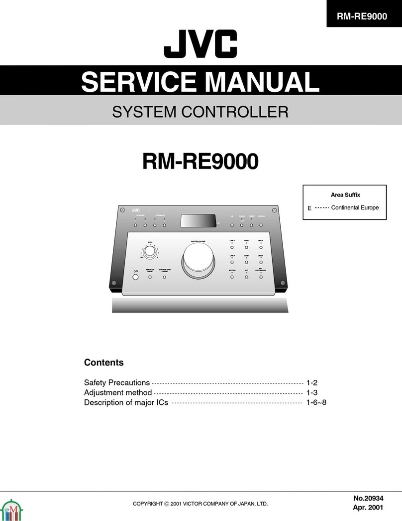
JVC RX-ES9SL User manual

SERVICE MANUAL
COPYRIGHT © 2003 VICTOR COMPANY OF JAPAN, LIMITED No.MB127
2003/12
HOME CINEMA CONTROL CENTER
MB127200312 RX-ES9SL
TABLE OF CONTENTS
1 PRECAUTION. . . . . . . . . . . . . . . . . . . . . . . . . . . . . . . . . . . . . . . . . . . . . . . . . . . . . . . . . . . . . . . . . . . . . . . . . 1-3
2 SPECIFIC SERVICE INSTRUCTIONS. . . . . . . . . . . . . . . . . . . . . . . . . . . . . . . . . . . . . . . . . . . . . . . . . . . . . . 1-5
3 DISASSEMBLY . . . . . . . . . . . . . . . . . . . . . . . . . . . . . . . . . . . . . . . . . . . . . . . . . . . . . . . . . . . . . . . . . . . . . . . 1-6
4 ADJUSTMENT . . . . . . . . . . . . . . . . . . . . . . . . . . . . . . . . . . . . . . . . . . . . . . . . . . . . . . . . . . . . . . . . . . . . . . . 1-12
5 TROUBLESHOOTING . . . . . . . . . . . . . . . . . . . . . . . . . . . . . . . . . . . . . . . . . . . . . . . . . . . . . . . . . . . . . . . . . 1-13
Area Suffix
B ------------------------ U.K.
E ---- Continental Europe
EN ----- Northern Europe

1-2 (No.MB127)
SPECIFICATION
Designs & specifications are subject to change without notice
Amplifier
Output Power
At stereo operation Front channels 100 W per channel, min. RMS, both channels driven into 8 Ωat 1 kHz with no more than 10%
total harmonic distortion. IEC268-3)
At surround operation Front channels 100 W per channel, min. RMS, driven into 8 Ωat 1 kHz with no more than 0.8% total harmonic
distortion.
Center channel 100 W, min. RMS, driven into 8 Ωat 1 kHz, with no more than 0.8% total harmonic distortion.
Surround
channels 100 W per channel, min. RMS, driven into 8 Ωat 1 kHz, with no more than 0.8% total harmonic
distortion.
Audio
Audio Input
Sensitivity/Impedance (1 kHz) DVD, DVD MULTI, STB, VR, TV : 260 mV/47 kΩ
Audio Input (DIGITAL IN)* Coaxial DIGITAL 1 (VR) : 0.5 V(p-p)/75 Ω
Optical DIGITAL 2/3 (STB/DVD) : -21 dBm to -15 dBm (660 nm ±30 nm)
* Corresponding to Linear PCM, Dolby Digital, and DTS Digital Surround (with sampling frequency -32 kHz, 44.1 kHz, 48 kHz).
Audio Output Level VR, TV : 250 mV
Signal-to-Noise Ratio
('66 IHF/DIN) DVD MULTI : 87 dB/62 dB
Frequency Response (8 Ω) DVD, STB, VR, TV : 20 Hz to 20 kHz (±1 dB)
Tone Control Bass (100 Hz) : ±10 dB ±2 dB
Treble (10 kHz) : ±10 dB ±2 dB
Bass Boost +4 dB ± 1 dB at 100 Hz
Video
Video Input
Sensitivity/Impedance (1 kHz) Composite video : DVD, STB, VR, TV 1 V(p-p)/75 Ω
S-VIDEO : DVD, STB, VR (Y: luminance) : 1 V(p-p)/75 Ω
(C: chrominance) : 0.286 V(p-p)/75 Ω
RGB : DVD, STB, VR 0.7 V(p-p)/75 Ω
Video Output Level/Impedance
(1 kHz) Composite video : VR, TV 1 V(p-p)/75 Ω
S-VIDEO : TV (Y: luminance) : 1 V(p-p)/75 Ω
(C: chrominance) : 0.286 V(p-p)/75 Ω
RGB : TV 0.7 V(p-p)/75 Ω
Signal-to-Noise Ratio (S/N) 45 dB
Synchronize Negative
FM tuner (IHF)
Tuning Range 87.50 MHz to 108.00 MHz
Usable Sensitivity Monaural : 17.0 dBf (1.95 µV/75 Ω)
50 dB Quieting Sensitivity Monaural : 21.3 dBf (3.2 µV/75 Ω)
Stereo : 41.3 dBf (31.5 µV/75 Ω)
Stereo Separation at REC OUT 35 dB at 1 kHz
AM (MW) tuner
Tuning Range MW : 522 kHz to 1 629 kHz
General
Power Requirements AC 230 V, 50 Hz
Power Consumption 105 W (at operation)
2 W (in standby mode)
Dimensions (W ×H ×D) 435 mm ×69.5 mm ×330.5 mm
Mass 6.6 kg

(No.MB127)1-3
SECTION 1
PRECAUTION
1.1 Safety Precautions
(1) This design of this product contains special hardware and
many circuits and components specially for safety purpos-
es. For continued protection, no changes should be made
to the original design unless authorized in writing by the
manufacturer. Replacement parts must be identical to
those used in the original circuits. Services should be per-
formed by qualified personnel only.
(2) Alterations of the design or circuitry of the product should
not be made. Any design alterations of the product should
not be made. Any design alterations or additions will void
the manufacturers warranty and will further relieve the
manufacture of responsibility for personal injury or property
damage resulting therefrom.
(3) Many electrical and mechanical parts in the products have
special safety-related characteristics. These characteris-
tics are often not evident from visual inspection nor can the
protection afforded by them necessarily be obtained by us-
ing replacement components rated for higher voltage, watt-
age, etc. Replacement parts which have these special
safety characteristics are identified in the Parts List of Ser-
vice Manual. Electrical components having such features
are identified by shading on the schematics and by ( ) on
the Parts List in the Service Manual. The use of a substitute
replacement which does not have the same safety charac-
teristics as the recommended replacement parts shown in
the Parts List of Service Manual may create shock, fire, or
other hazards.
(4) The leads in the products are routed and dressed with ties,
clamps, tubings, barriers and the like to be separated from
live parts, high temperature parts, moving parts and/or
sharp edges for the prevention of electric shock and fire
hazard. When service is required, the original lead routing
and dress should be observed, and it should be confirmed
that they have been returned to normal, after reassem-
bling.
(5) Leakage shock hazard testing
After reassembling the product, always perform an isola-
tion check on the exposed metal parts of the product (an-
tenna terminals, knobs, metal cabinet, screw heads,
headphone jack, control shafts, etc.) to be sure the product
is safe to operate without danger of electrical shock.Do not
use a line isolation transformer during this check.
• Plug the AC line cord directly into the AC outlet. Using a
"Leakage Current Tester", measure the leakage current
from each exposed metal parts of the cabinet, particular-
ly any exposed metal part having a return path to the
chassis, to a known good earth ground. Any leakage cur-
rent must not exceed 0.5mA AC (r.m.s.).
• Alternate check method
Plug the AC line cord directly into the AC outlet. Use an
AC voltmeter having, 1,000Ωper volt or more sensitivity
in the following manner. Connect a 1,500Ω10W resistor
paralleled by a 0.15µF AC-type capacitor between an ex-
posed metal part and a known good earth ground.
Measure the AC voltage across the resistor with the AC
voltmeter.
Move the resistor connection to each exposed metal
part, particularly any exposed metal part having a return
path to the chassis, and measure the AC voltage across
the resistor. Now, reverse the plug in the AC outlet and
repeat each measurement. Voltage measured any must
not exceed 0.75 V AC (r.m.s.). This corresponds to 0.5µ
mA AC (r.m.s.).
1.2 Warning
(1) This equipment has been designed and manufactured to
meet international safety standards.
(2) It is the legal responsibility of the repairer to ensure that
these safety standards are maintained.
(3) Repairs must be made in accordance with the relevant
safety standards.
(4) It is essential that safety critical components are replaced
by approved parts.
(5) If mains voltage selector is provided, check setting for local
voltage.
1.3 Caution
Burrs formed during molding may be left over on some parts
of the chassis.
Therefore, pay attention to such burrs in the case of pre-
forming repair of this system.
1.4 Critical parts for safety
In regard with component parts appearing on the silk-screen
printed side (parts side) of the PWB diagrams, the parts that are
printed over with black such as the resistor ( ), diode ( )
and ICP ( ) or identified by the " " mark nearby are critical
for safety. When replacing them, be sure to use the parts of the
same type and rating as specified by the manufacturer.
(This regulation dose not Except the J and C version)
Good earth ground
Place this
probe on
each exposed
metal part.
AC VOLTMETER
(Having 1000
ohms/volts,
or more sensitivity)
1500 10W
0.15 F AC TYPE

1-4 (No.MB127)
1.5 Safety Precautions (U.K only)
(1) This design of this product contains special hardware and many circuits and components specially for safety purposes. For con-
tinued protection, no changes should be made to the original design unless authorized in writing by the manufacturer. Replace-
ment parts must be identical to those used in the original circuits.
(2) Any unauthorised design alterations or additions will void the manufacturer's guarantee; furthermore the manufacturer cannot
accept responsibility for personal injury or property damage resulting therefrom.
(3) Essential safety critical components are identified by ( ) on the Parts List and by shading on the schematics, and must never
be replaced by parts other than those listed in the manual. Please note however that many electrical and mechanical parts in
the product have special safety related characteristics. These characteristics are often not evident from visual inspection. Parts
other than specified by the manufacturer may not have the same safety characteristics as the recommended replacement parts
shown in the Parts List of the Service Manual and may create shock, fire, or other hazards.
(4) The leads in the products are routed and dressed with ties, clamps, tubings, barriers and the like to be separated from live parts,
high temperature parts, moving parts and/or sharp edges for the prevention of electric shock and fire hazard. When service is
required, the original lead routing and dress should be observed, and it should be confirmed that they have been returned to
normal, after re-assembling.
1.5.1 Warning
(1) Service should be performed by qualified personnel only.
(2) This equipment has been designed and manufactured to meet international safety standards.
(3) It is the legal responsibility of the repairer to ensure that these safety standards are maintained.
(4) Repairs must be made in accordance with the relevant safety standards.
(5) It is essential that safety critical components are replaced by approved parts.
(6) If mains voltage selector is provided, check setting for local voltage.
Burrs formed during molding may be left over on some parts of the chassis. Therefore,
pay attention to such burrs in the case of preforming repair of this system.

(No.MB127)1-5
SECTION 2
SPECIFIC SERVICE INSTRUCTIONS
This service manual does not describe SPECIFIC SERVICE INSTRUCTIONS.

1-6 (No.MB127)
SECTION 3
DISASSEMBLY
3.1 Main body section
3.1.1 Removing the top cover
(See Figs.1 and 2)
(1) From the back side of the main body, remove the three
screws Aattaching the top cover. (See Fig.1)
(2) From the both sides of the main body, remove the four
screws Battaching the top cover. (See Fig.1)
(3) Remove the top cover by moving up the back part of the top
cover and release the six joints ausing a longer driver from
the inside. (See Fig.2.)
Note:
•Do not damage any part and board inside the main body when
releasing the joints ausing a longer driver.
Fig.1
3.1.2 Removing the front panel assembly
(See Figs.2 to 4.)
• Prior to perform the following procedures, remove the top cov-
er.
(1) From the top side of the main body, cut the tie bands and
disconnect the wire from the connector CN451 on the main
board. (See Fig.2.)
(2) From the bottom side of the main body, remove the four
screws Cattaching the front panel assembly. (See Fig.3.)
(3) From the both sides of the main body, release the joints b
and remove the front panel assembly in the direction of the
arrow. (See Fig.4.)
(4) From the top side of the main body, remove the screw Dat-
taching the earth wire on the DC power board. (See Fig.2.)
References:
• After attaching the front panel assembly, bundling the wires
using the new tie bands.
• When attaching the screw D, attach the earth wire with it.
Fig.3
Fig.2
Fig.4
A
Bx2 Bx2
Top cover
C
Front panel assembly
CN451
Main board
Front panel assembly
Joints a
Tie bands
Earth wire
D
DC power
board
Front panel assembly
Joint b

(No.MB127)1-7
3.1.3 Removing the tuner
(See Figs.5 and 6.)
• Prior to perform the following procedures, remove the top cov-
er.
(1) From the top side of the main body, disconnect the card
wire from the connector CN1 on the tuner. (See Fig.5.)
(2) From the back side of the main body, remove the two
screws Eattaching the tuner to the rear panel. (See Fig.6.)
Fig.5
Fig.6
3.1.4 Removing the rear panel
(See Fig.7)
• Prior to perform the following procedures, remove the top cover.
(1) From the back side of the main body, remove strain relief
from the rear panel in the direction of the arrow.
(2) Remove the twenty screws Fattaching the rear panel.
Fig.7
3.1.5 Removing the digital input board
(See Fig.8)
• Prior to perform the following procedures, remove the top cov-
er, tuner and rear panel.
Reference:
• Remove the tuner as required.
(1) From the top side of the main body, remove the connector
CN521 on the digital input board in an upward direction.
(2) From the reverse side of the digital input board, disconnect
the card wire from the connector CN522 on the digital input
board.
Fig.8
Card wire
Tuner CN1
ERear panel
F
F
Rear panel
Strain relief
Digital input board
CN522
CN521

1-8 (No.MB127)
3.1.6 Removing the digital output board
(See Fig.9)
• Prior to perform the following procedures, remove the top cov-
er, tuner, rear panel and digital input board.
Reference:
• Remove the tuner as required.
(1) Disconnect the card wires from the connectors CN513 and
CN514 on the digital output board.
(2) Remove the screw Gattaching the digital output board.
Fig.9
3.1.7 Removing the AC power supply board
(See Fig.10)
• Prior to perform the following procedures, remove the top cov-
er and tuner.
(1) From the top side of the main body, disconnect the power
cord from the connector CN203 on the AC power supply
board and remove it from the rear panel.
(2) Cut the tie bands and disconnect the wire from the connec-
tor CN218 on the DC power board.
(3) Remove the three screws Hattaching the AC power supply
board.
(4) Disconnect the wire from the connector CN202 on the AC
power supply board and remove the wire holders from the
reverse side of the AC power supply board.
Reference:
• When attaching the three screws H, attach the wire holder
with it.
Fig.10
Card wires
Digital output board CN513
CN514 G
CN202
CN203
DC power board
Power cord
CN218
AC power supply board
Wire holder
Rear panel
Tie bands
H
H
Wire
holder
Wire
holder

(No.MB127)1-9
3.1.8 2.1.8 Removing the power transformer
(See Fig.11)
• Prior to perform the following procedures, remove the top cov-
er and front panel assembly.
(1) From the top side of main body, disconnect the wire from
the connector CN202 on the AC power supply board.
(2) Remove the strain relief holding the power cord and re-
move the three screws Hattaching the AC power supply
board.
(3) Lift the AC power supply board and remove the wire hold-
ers from the reverse side of the AC power board.
(4) Cut the tie band.
(5) Disconnect the wire from the connector CN201 on the DC
power board.
(6) Disconnect the wire from the connector CN702 on the rec-
tifier board.
(7) Remove the four screws Jattaching the power transform-
er.
Reference:
• After attaching the front panel assembly, bundling the wires
using the new tie bands.
Fig.11
3.1.9 Removing the fan motor
(See Figs.12 and 13)
• Prior to perform the following procedures, remove the top cov-
er.
(1) From the top side of the main body, cut the tie bands and
disconnect the wire from the connector CN207 on the DC
power board. (See Fig.12.)
(2) Remove the screw Kand screw K’ attaching the fan as-
sembly, then remove the fan assembly. (See Fig.12.)
(3) Remove the two screws Lattaching the fan motor to the fan
bracket. (See Fig.13.)
Reference:
• After attaching the screw K’, attach the wire holder with it.
Fig.12
Fig.13
CN202
DC power board
Power cord
Wire holder
Rectifier board
AC Power supply board
Strain relief
CN201 CN702
Power transformer
Tie band
H
JJ
Fan assembly
DC power board
CN207
Tie bands
K
K'
Wire holder
L
Fan bracket Fan moter

1-10 (No.MB127)
3.1.10 Removing the DC power board
(See Fig.14)
• Prior to perform the following procedures, remove the top cov-
er, front panel assembly, rear panel and digital input board.
(1) From the top side of the main body, disconnect the wires
from the connectors (CN201, CN206, CN207, CN211,
CN218, CN510, CN520 and CN711) on the DC power
board.
(2) Disconnect the parallel wire from the connector CN712 on
the amp. board.
(3) Remove the two screws Mattaching the DC power board.
Fig.14
3.1.11 Removing the main board
(See Fig.15)
• Prior to perform the following procedures, remove the top cov-
er, front panel assembly, rear panel, digital input board, digital
output board, AC power supply board and DC power board.
(1) From the top side of the main body, disconnect the wires
from the connector CN525 on the main board.
(2) Disconnect the wires from the connectors CN516 and
CN519 on the amp board.
(3) Remove the two screws Nattaching the main board.
Reference:
• When attaching the two screws N, attach the wire holder
with it.
3.1.12 Removing the amp. board
(See Fig.15)
• Prior to perform the following procedures, remove the top cov-
er, front panel assembly, rear panel, digital input board, digital
output board, AC power supply board and DC power board.
(1) From the top side of the main body, disconnect the wires
from the connectors CN516 and CN519 on the amp. board.
(2) Disconnect the wire from the connector CN525 on the main
board.
(3) Disconnect the wire from the connector CN703 on the rec-
tifier board.
(4) Remove the four screws Pattaching the amp. board. Fig.15
CN520
CN510
CN210 CN711
CN712
CN211
CN207
CN206
Amp. board
CN218
M
M
DC power board
P
P
N
P
Main board
CN516
CN519
CN703
CN525
Wire holder
Amp. board
Rectifier board
P

(No.MB127)1-11
3.1.13 Removing the rectifier board
(See Fig.16)
• Prior to perform the following procedures, remove the top cov-
er and front panel assembly.
(1) From the top side of the main body, disconnect the wires
from the connectors CN702 and CN703 on the rectifier
board.
(2) Disconnect the parallel wire from the connector CN711 on
the DC power board.
(3) Remove the two screws Qattaching the rectifier board.
3.1.14 Removing the headphone jack board
(See Fig.16)
• Prior to perform the following procedures, remove the top cov-
er and the front panel.
(1) From the top side of the main body, cut the tie bands.
(2) Disconnect the wire from the connector CN206 on the DC
power board.
(3) Remove the screw Rattaching the headphone jack board.
Reference:
• After attaching the front panel assembly, bundling the wires
using the new tie bands. Fig.16
3.1.15 Removing the FL board
(See Fig.17)
• Prior to perform the following procedures, remove the top cov-
er and front panel assembly.
(1) From the inside of the front panel assembly, remove the six
screws Sattaching the FL board.
(2) Disconnect the wire from the connector CN403 on the FL
board.
(3) Disconnect the connector CN401 on the FL board in an up-
ward direction.
3.1.16 Removing the volume board
(See Fig.17)
• Prior to perform the following procedures, remove the top cov-
er and front panel assembly.
(1) From the inside of the front panel assembly, remove three
screws Tattaching the volume board.
(2) Disconnect the wire from the connector CN403 on the FL
board.
Fig.17
3.1.17 Removing the SW board
(See Fig.18)
• Prior to perform the following procedure, remove the top cover,
front panel assembly and FL board.
(1) From the inside of the front panel assembly, remove the
seven screws Uattaching the SW board.
Fig.18
CN206
DC power board
Headphone jack board Rectifier board
CN703
CN702
CN711
Tie band
R
Q Q
TS
Front panel assembly
FL board
Volume board
CN403
CN401
U
Front panel assembly
SW board

1-12 (No.MB127)
SECTION 4
ADJUSTMENT
This service manual does not describe ADJUSTMENT.

(No.MB127)1-13
SECTION 5
TROUBLESHOOTING
Thisservice manual does not describe TROUBLESHOOTING.

(No.MB127)
AV & MULTIMEDIA COMPANY AUDIO/VIDEO SYSTEMS CATEGORY 10-1,1chome,Ohwatari-machi,Maebashi-city,371-8543,Japan
VICTOR COMPANY OF JAPAN, LIMITED
WPC
Printed in Japan

SCHEMATIC DIAGRAMS
No.MB127SCH
2003/12
COPYRIGHT 2003 VICTOR COMPANY OF JAPAN, LTD.
RX-ES9SL
Contents
Block diagram
Standard schematic diagrams
Printed circuit boards
2-1
2-2
2-10 to 15
CD-ROM No.SML200312
Area suffix
B ------------------------------- U.K.
E ----------- Continental Europe
EN ------------ Northern Europe
HOME CINEMA CONTROL CENTER

In regard with component parts appearing on the silk-screen printed side (parts side) of the PWB diagrams, the
parts that are printed over with black such as the resistor ( ), diode ( ) and ICP ( ) or identified by the " "
mark nearby are critical for safety.
(This regulation does not correspond to J and C version.)

2-1
S.MUTE
CDTI,CDTO
CS,CCLK
DSP_RST
MICS,MILP
MIDIO,MICK
MIACK
LOCK,ERR
DIGITAL0
FORMAT
CHANNEL
RST_DET
IC502
SOURCE
SELECTOR
IC401
SYSTEM CONTROL
&
FL DRIVER
DI401
FL DISPLAY
Q231
RY701
Main board
FL board
DC power board AC power supply board
TU_CLK
TU_CE
TU_DATAI
TU_DATAO
RDS_DATA
TUNER L/R
TU_L/R
Main
plug
CN703
CN203
T202
Tr a n s .
CN218 CN202
T201
Power
trans.
CN702FW701
Rectifier board
RY202
CN211
RY201
DVD_L/R
IC503
6-CH
VOL.IC
DVD_L/R
MULTI_SL/SR
MULTI_C/SW
IC501
SYSTEM
CONTROL
VIDEO1 to VIDEO4, SLOW_M, SLOW_L DSP_RESET
DSP_READY
DSP_COMMAND
DSP_STATUS
DSP_CLK
CN502
DSP_C
DSP_LFE
DSP_SL
DSP_SR
DSP_L/R
L/R OUT
SL/SR OUT
C OUT
SBWFR OUT
CN506
J504
SUB
WOOFER
OUT
FW501
CN516
CN451
CN509
Amp. board
CN519
IC801,IC802
IC804,IC811
IC812
Amp.
CN801
IC901,IC902
IC911
Amp.
CN11
Q115 to Q118
Power amp.
CN12
CN22
Power amp. board Power amp. drv. board
IC11
IC12
Driver
CN802
CN11
CN12
Power amp. board
CN901
CN11
CN12
Power amp. board
CN301
CN11
CN12
Power amp. board
CN302
CN11
CN12
Power amp. board
IC301,IC302
IC304,IC311
IC312
Amp.
SL
SR
C
L
R
CN725
L/R,C
SL/SR
RY301
RY801
RY901
Q717
Q718
Q719
CN712
D231 to D233
Q213
Q218
Q219
A+5V
REG.
Q211
Q212
Q216
Q217
D+5V
REG.
Q210
Q214
Q215
TU+9V
REG.
A+5V
D+5V
TU+9V
TV DIRECT
Q209
+5V
REG.
+5V
CN412
F1,F2
Q204
-VPP
REG.
-VPP
Q205
D201
to
D204
CN520
CN510
Q203
B+5V
POWER,FAN+V
Q201
POWER
Q225
Q207
Q208
-7V
+7V
REG.
CN510
+7V
-7V
+5V
CN711
D208
to
D211
CN208 CN201
L/R
IC571
AMP.
L
R
SL
SR
C
+S2B
-S2B +B,-B
TO
FAN MOTOR
FAN+V
POWER
CN530 CN540
HP_SW
HP_RELAY
FAN V
HP_RELAY
HP_SW
LED_DIMMER1
LED_DIMMER2
M_COMMAND
M_CLK
M_STATUS
M_CS
M_BUSY
M_RESET
CN401
M_CLK,M_COMMAND
M_STATUS,M_CS
M_BUSY,M_RESET
LED_DIMMER1
CN402
F1,F2
-VPP
CN404
Q403
LED_DIMMER2
KEY_IN1 to 3
STANDBY_IND
IND control signal
CN414
SW board
CN413
Volume board
CN403
IC402
REMOCON
RECEIVER
JS401
JS402
VOL1,VOL2
JOG1,JOG2
REMOCON
IC601
AD/DA
CONVERTER
Digital input board
COAX IN
OPT IN1
OPT IN2
IC609
IC610
AMP.
CN521
IC650
IC651
AMP.
IC661
AMP.
IC690
IC691
AMP.
IN_L
IN_R
DSP_L
DSP_R
DSP_SL
DSP_SR
DSP_C
DSP_LFE
IC671
Digital signal
controller
IC631
DSP
IC641
SDRAM
SDTI1 to 3
SDTO
BCLK,LRCLK
A0 to 16
I/O0 to 7
CE,OE,WE
CN522
DSP_RESET
DSP_READY
DSP_COMMAND
DSP_STATUS
DSP_CLK
IC611
IC612
IC621
SELECT1
to
SELECT4
Tu n e r
CN1
SL
SL
C
L
R
SL
SR
C
L
R
SL/SR
C
L/R
CN207
CN206
Headphone jack
board
J201
PHONES
FW206
LIN+/-
RIN+/-
LOUT1
ROUT1
LOUT2
ROUT2
LOUT3
ROUT3
IC652
IC682
IC662
SMUTE
Q672
IC672
OR
ANT/T.TONE
Q2501
SMUTE
Q670
DSP_STATUS
X671
X631
Q101
to
Q114
AMP.
CN22
Power amp. drv. board
CN22
Power amp. drv. board
CN22
Power amp. drv. board
CN22
Power amp. drv. board
S_RELAY
C_RELAY
F_RELAY
FW702
+5V
+S2B
+S2B
-S2B D701
to
D704
SMART SETUP C
SMART SETUP L/R
SMART SETUP SL/SR
Q511
to
Q519
SOURCE MUTE
SUBWFR MUTE
FR_RELAY
C_RELAY
SURR_RELAY
X501
POWER
TV DIRECT
Q531
Q535
FAN_M
FAN_H
IC504 1/2
Q525
to Q527
IN_LEVEL1
IN_LEVEL2
IN_LEVEL3
L/R OUT
IC504 2/2
Q521
to
Q523
TU_MUTE
+S2B,B+5V
+5V,+/-7V
X401
Q671
Q673
DSP_LFE LFE_MIX
L/R IN
IC701
INV.
X711
X712
IC708
IC709
Digital amplifier
IC702
IC703
Q115 to Q118
Power amp.
IC11
IC12
Driver
Q101
to
Q114
AMP.
Q115 to Q118
Power amp.
IC11
IC12
Driver
Q101
to
Q114
AMP.
Q115 to Q118
Power amp.
IC11
IC12
Driver
Q101
to
Q114
AMP.
Q115 to Q118
Power amp.
IC11
IC12
Driver
Q101
to
Q114
AMP.
Q3401
to
Q1304
Q3801
to
Q1804
Q1901
Q1903
IC371
IC871
IC971
Amp.
CN525
MULTI_SL/SR
MULTI_C/SW
CN505
CN713
IC505
RDS
RDS_RESET
RDS_READY
RDS_DAVN
RDS_DATA
VCR_LOUT/ROUT
TV_LOUT/ROUT
VCR_L/R
TV_L/R
Q504 to Q509
DRV
STB_SLOW
DVD_SLOW
VCR_SLOW
DVD_L/R
STB_L/R
DVD_R/C,G,B
DVD_Ys,DVD_V/Y
TV_LINK
CN503 CN504 CN501
J3501
SCART VR
J3502
SCART TV
VCR_L/R, VCR_LOUT/ROUT
CN513
TV_L/R,TV_LOUT/ROUT
CN514
VCR_R/C,G,B IC511 to IC513
VIDEO
SELECTOR
STB_R/C,G,B
DVD_R/C,G,B
VIDEO1
VIDEO4
IC514
VIDEO
SELECTOR
STB_V/Y
DVD_V/Y
VCR_SLOW,TV_LINK
TV_V/Y
VIDEO1
VIDEO2
VIDEO3
VCR_V/Y
TV_V/Y IC515
MPX
VIDEO1
VIDEO3
VIDEO4
STB_Ys
DVD_Ys
VCR_Ys
Ys_OUT
VCR_V/Y,VCR_Ys
Q3501
to
Q3506
Q3507
Q3508
Digital output board
Q3414
Q3415
TV_SLOW_OUT
TV_LINK Q3511
Q3512
Q3513
J501
SCART DVD
J502
SCART STB
STB_R/C,G,B
STB_Ys,STB_V/Y
TV_LINK
AM
FM
R OUT
L OUT
SL OUT
SR OUT
C OUT
ST701
DVD_SIN, STB_SIN, VCR_SIN
Block diagram

2-2
SHEET 1
Standard schematic diagrams
Primary / Regulator section
(SHEET 5) (SHEET 2) (SHEET 5)
(SHEET 5)
(SHEET 7)
(SHEET 2)
Parts are safety assurance parts.
When replacing those parts make
sure to use the specified one.
!
!
!
!
!
!
!
!
!
!
!
!
!
!
!
!!!
!
!
!
!
!
B307
C251
CN202
R251
EP201
CN203
Q223
CN201
Q201
R202
B203
Q205
D223
R210
R211
Q213
Q211
Q210
R241
Q212
Q209
B129
Q208 Q207 R215R217R221
CN207
R236
TH201
C242
C241
CN702
R230
R229
D213
R225
R216R218 D212
R222
R232
R233
R226
R231
R237
D215D216D217
D220
R234
D219
D222
R235
C226
C225
R227
Q216
Q214
Q218
Q215
Q219
Q217
R228
Q221
R223
R224
R219
R220
R238
R239D221
Q220
D235
D232
RY701
D225
Q225
RY202
CN206
FW702 CN510
CN211
CN703
C232
C231
C233
J201
D231
FW206
CN208
D233
B201
R245
D703
D701
C705
C701
C702
C234
R701
CN711
CN520
EP701
Q231
R203
R242
FW701
CN412
CN218
Q204
C214
D224
R209
EP204
R208
C208C207
C213
C212
C210 C211
C209
D209
D210
D208
D211
Q203
D202
D203
C203
D201
D204
D205
C206
C201
T202
RY201
C202
F204
EP202
F205
R207
F203
C215
F202
D218
C221
C222
C223
C224
Q222
R705R706
R261
R262
D702
D704
C704
C703
D705
C205
D207
R206
22/16
10k
KRC111S
KRC105S
10
KTA1046/Y
MTZJ33C
10
5.6k
2SD2395/EF
2SD2395/EF
2SD2395/EF/
82
2SD2395/EF
2SD2395/EF 2SD2395/EF KTA1046/Y 101010
10
4.7
100/100
220/50
4.7
4.7
10EDB20
10
1.5k1.5k 10EDB20
3.3k
2.2
2.2
1k
1.8k
3.3k
MTZJ7.5CMTZJ7.5CMTZJ6.2C
MTZJ5.6C
1k
MTZJ5.6C
10EDB20
100k
100/25
100/25
39k
KRA102S
KRA102S
KRA102S
KRC102S
KRC102S
KRC102S
47k
KRC111S
1k
100k
22k
47k
510
100kMA111
KRC111S
MA111
10EDB20
QSK0127-002
MA111
KRC105S
QSK0127-001
0.015
0.015
0.1
10EDB20
10EDB20
2.2
30PRA20-FC
0.1/160
6800/42
6800/42
0.022
82
KRC102S
10
2.2k
KTC3200/GL/
1/50
MTZJ6.2C
10
100k
0.1MY0.1MY
0.047MY
0.047MY
3300/25 1000/25
0.1MY
10EDB20
10DDA20-FD
10DDA20-FD
10EDB20
KTC3203/OY
10EDB20
10EDB20
470/25
10EDB20
10EDB20
MA111
470/16
0.0047
QQT0281-002
QSK0142-001
0.0047/100
2.7
47/50
MTZJ10B
100/25
100/25
100/25
1000/25
KRC111S
100k100k
22
22
0.1/160
0.1/160
MA111
0.0047
MTZJ6.2C
820
+S2B
-S2B
HP_L
HP_R
!
!
!
!!
!!
!
!
!
!
!
!
!
!
!
!
!
!
!
!
!
!
!
!
!
!
!
!
!
!
!
!
!
!
!
!
!
!!
!
!
!

2-3
SHEET 2
(SHEET 5)
(SHEET 3)
(SHEET 1)
(SHEET 1)
IC709 PIN5 (SHEET 2) IC709 PIN2 (SHEET 2)
(SHEET 5)
(SHEET 5)
Speaker terminal / PWM modulator / Low pass filter section
Parts are safety assurance parts.
When replacing those parts make
sure to use the specified one.
C303
C301
R305
R303
R301 R307
R313
R315
R311
R317
R309
C305
C309 C311
C307
R319
IC301
R323
R325
D721
R761
C751
C315
C313
Q301
IC302
IC311
R335 R341
R333
R331
R337
R339
R343
R345
Q303
C319
C317
IC301
C1301
C1303
IC871
R379
R351
R357
L1301
R353
C373
R355 R361
L1303
R786
D1313
D371
R1331
R1333
R1335
R1343
R1337 R1339
Q1307
C304
C302
R306
R304
R302 R308
R314
R316
R312
R318
R310
C306
C310 C312
C308
R320
IC304
R324
R326
D722 R765
C316
C314
Q302
IC302
IC312
R336
R342
R334
R332
R338
R340
R344
R346
Q304
C320
C318
C762
D753
D1314
R1309
R1311
R1313
R1321
C371
R371
IC304
R352
L1304
C761
R375
D1813
R373
R1315
R1332
R1334
R1336
R1338 R1340
Q1308
R1317
Q1303
D1814
D1913
R359
C325
C321
C323
C1302
C1304
IC371
R380
L1302
C1306
C374
R1310
R1312
R1314
C803
C801
R805
R803
R801 R807
R813
R815
R811
R817
R809
C805
C809 C811
C807
R819
IC801
R823
R1322
C1305
R1316 R1318
Q1304
C1805
R358
R354
R356 R362
R360
C326
C322
C324
C1801
C1803
D372
R825
R764
R766
R763
C815
C813
Q801
IC802
IC811
R835
R841
R833
R831
R837
R839
R843
R845
Q803
C819
C817
L1801
R391
C1806
R1809
C372
R372
C1802
C1804
L1803
R392
R1811
R376
C1905
R374
R1813 R1831
R1833
R1835
R1837 R1839
Q1807
R1821
R1815
D728
R1817
Q1803
R725
IC801
R851
R857
R853
R855 R861
R859
C825
C821
C823
IC971
R879
L1802
C804
C802
R806
R804
R802 R808
R814
R816
R812
R818
R810
C806
C810 C812
C808
R820
IC804
R824
R826
R762
C816
C814
Q802
IC802
IC812
R836
R842
R834
R832
R838
R840
R844
R846
Q804
C820
C818
R891
R726
C873
R1810
R1812
R1814
IC804
R852
D871
R858
R854
L1804
R892
R1822
D752
D727
R1832
R1834
R1836
R1838 R1840
Q1808
R1816 R1818
Q1804
C720
R856 R862
R860
C826
C822
C824
C1901
C1903
C871
R871
L1901
R991
R875
C903
C901
R905
R903
R901 R907
R913
R915
R911
R917
R909
C905
C909 C911
C907
R919
IC901
R923
R925
C915
C913
Q901
IC902
IC911
R935
R941
R933
R931
R937
R939
R943
R945
Q903
C919
C917
R775
R873
R1909
R1911
R1913
R1921
IC871
R880
C874
D872
L1903
R776
Q743
D731
D726
R1915 R1917
R1931
R1933
R1935
R1937 R1939
Q1907Q1903
D725
IC901
R951
R957
R953
R955 R961
R959
C925
C921
C923
C872
R872
R876R874
IC971
R979
C973
D971
RY301
RY801
RY901
D732
R1355
R738
Q721
R1351
R1851
R1951
C719
D729
CN712
R987
R888
R887
R388
R387
R385
R386
C1359
C1360
C1859
C1860
C1959
ST701
IC705
R885
R886
R393
R985
R1356
R1855
C721
C722
R1856
R1955
C971
R971
R975R973
C931
Q717
Q718
Q719
C731
C732
IC701
IC702
IC703
Q711
Q712
Q713
Q714
Q715
R711
R712
R713
R714
R718
R719
R722
CN516
R723
R720
R715
R721
R717
R716
C715
C716
C718
C717
C711
C712
C713
C714
X712
X711
C331
C333
C332
C334
C833
C831
C834
C832
EP711
CN519
C933
R777
R731
D1311
D733
R781
IC371
D1312
D1811
D1812
D1911
R394
C730
R893
R894
R993
Q745
R782
R783
CN713
C981
C882
C881
C382
C381
CN901 CN802
R377
CN801
C1325
C1327
CN302
R381
C1313
C1315
R1341
D1305
D1307
Q1305
C1361
C375
R1319
CN301
C1326
C1328
D1301
D1303
R1342
R1344
D1306
D1308
Q1306
Q1301
C1314
C1316
R785
R378
R1320
D1302
D1304
Q1302
R382
C327
C1813
C1815
D751
C376
C328C827C828
C1825
C1827
R1819
R1841
R1843
D1805
D1807
Q1805
D1801
D1803
Q1801
C927
C1814
Q731
C1363
C1816
R877
R1820
R881
C1331
C1826
C1828
C875
D1802
D1804
R1842
R1844
D1806
D1808
Q1806
Q1802
C1332C1831C1832C1931
C1913
C1915
C1362C1364C1861
R1919
D1901
D1903
R878
R882
C1925
C1927
C876
R1941
R1943
D1905
D1907
Q1905
Q1901
R977
R981
D715
R737
C735
D1351D1851D1951
C1951 C1953 C1854 C1852 C1851C1853 C1351C1353C1352C1354
C1863C1862C1864C1961C1963
R1353R1354R1853R1953 R1854
D373D374D873D874
C728
C975
CN725
D973
R1303
R1325
R1326
R1304R1803
R1825R1826
R1804R1903
R1925
C1919
C1907 C1808
C1820 C1819
C1807 C1308
C1320 C1319
C1307
Q742
Q741
C729
R784
Q744
100/16
1/50
910
470
100k 47k
10k
10M
1k
10k
18k
220p
0.0022 0.0022
220p
820
NJM4580M
10k
3.3k
MA111
220
47/10
0.0022
180p
UMY1N
NJM2115
NJU7109F3
1k 22k
22k
1k
1k
100
820
KTA1268/GL/
1
330p
NJM4580M
330/50
330/50
HA17558AF
100k
4.7k
4.7k
22uH
27k
1/50
27k 2.2k
22uH
10k
MA111
MA704A
220
220
0.1
220
15k 15k
2SA1514K/RS/
100/16
1/50
910
470
100k 47k
10k
10M
1k
10k
18k
220p
0.0022 0.0022
220p
820
NJM4580M
10k
3.3k
MA111 100k
0.0022
180p
UMY1N
NJM2115
NJU7109F3
1k
22k
22k
1k
1k
100
820
KTA1268/GL/
1
330p
47/16
MA111
MA111
220
220
0.1
220
1/50
4.7k
NJM4580M
4.7k
22uH
47/16
470k
MA111
47k
15k
220
220
0.1
15k 15k
2SA1514K/RS/
15k
2SA1514K/RS/
MA111
MA111
2.2k
330/50
330/50
HA17558AF
100k
22uH
1/100
1/50
220
220
0.1
100/16
1/50
910
470
100k 47k
10k
10M
1k
10k
18k
220p
0.0022 0.0022
220p
820
NJM4580M
10k
220
1/100
15k 15k
2SA1514K/RS/
1/100
4.7k
27k
27k 2.2k
2.2k
330/50
330/50
MA704A
3.3k
3.3k
0
1.2k
0.0022
180p
UMY1N
NJM2115
NJU7109F3
1k
22k
22k
1k
1k
100
820
KTA1268/GL/
1
330p
22uH
100k
1/100
220
1/50
4.7k
330/50
330/50
22uH
100k
220
470k
1/100
47k
0.1 220
220
0.1
15k 15k
2SA1514K/RS/
220
15k
UDZS20B
15k
2SA1514K/RS/
10
NJM4580M
4.7k
4.7k
27k
27k 2.2k
2.2k
HA17558AF
100k
22uH
100/16
1/50
910
470
100k 47k
10k
10M
1k
10k
18k
220p
0.0022 0.0022
220p
820
NJM4580M
10k
3.3k
3.3k
0.0022
180p
UMY1N
NJM2115
NJU7109F3
1k
22k
22k
1k
1k
100
820
KTA1268/GL/
1
330p
100k
10
1/50
220
220
0.1
NJM4580M
4.7k
MA704A
4.7k
27k
22uH
100k
220
MA111
UDZS20B
220
220
0.1
15k 15k
2SA1514K/RS/
15k 15k
2SA1514K/RS/
100/25
27k 2.2k
2.2k
330/50
330/50
1/50
4.7k
22uH
100k
470k
100/16
1/50
910
470
100k 47k
10k
10M
1k
10k
18k
220p
0.0022 0.0022
220p
820
NJM4580M
10k
3.3k
0.0022
180p
UMY1N
NJM2115
NJU7109F3
1k
22k
22k
1k
1k
100
820
KTA1268/GL/
1
330p
390
47k
220
220
0.1
220
HA17558AF
100k
1/50
MA704A
22uH
390
2SD601A/RS/
UDZS6.8B
UDZS7.5B
15k 15k
220
220
0.1
15k 15k
2SA1514K/RS/2SA1514K/RS/
UDZS7.5B
NJM4580M
4.7k
4.7k
27k
27k 2.2k
2.2k
1/50
4.7k
470k47k
HA17558AF
100k
1/50
MA704A
QSK0127-001
QSK0127-001
QSK0127-001
MA111
10k
10k
KRC105S
82
82
82
100/25
UDZS6.8B
0
0
0
0
0
15k
15k
0.068
0.068
0.068
0.068
0.068
KIA78S05P
15k
15k
100k
15k
10k
10k
0.1
0.33
10k
47k
1/50
4.7k
470k47k
0.1
KRC102S
KRC102S
KRC102S
47/25
47/25
MM74HCU04SJ
MM74HC00SJ
MM74HC04SJ
KRC104S
KRC104S
KRC104S
KRC104S
KRC104S
1M
8.2k
1M
8.2k
1.2k
1.2k
1.2k
10k
1.2k
10k
10k
10k
10k
100p
100p
100p
100p
330p
330p
330p
330p
QAX0735-001
QAX0734-001
0.1
0.1
0.1
0.1
0.1
0.1
0.1
0.1
0.1
10k
4.7
MA111
MA111
18k
HA17558AF
MA111
MA111
MA111
MA111
100k
0.1
100k
100k
100k
2SD601A/RS/
3.3k
3.3k
0.0015
0.0015
0.0015
0.0015
0.0015
47
0.47
0.1
1k
0.47
0.1
100
MA111
MA111
2SA1514K/RS/
0.022
2.2/50
100
0.47
0.1
MA111
MA111
100
220
MA111
MA111
2SA1514K/RS/
2SA1514K/RS/
0.47
0.1
18k
47
100
MA111
MA111
2SA1514K/RS/
1k
0.1
0.47
0.1
MA111
2.2/50
0.10.10.1
0.47
0.1
100
100
220
MA111
MA111
2SA1514K/RS/
MA111
MA111
2SA1514K/RS/
0.1
0.47
KRA114S
0.022
0.1
47
100
1k
10/100
0.47
0.1
2.2/50
MA111
MA111
100
220
MA111
MA111
2SA1514K/RS/
2SA1514K/RS/
10/10010/10010/10010/100
0.47
0.1
0.0220.0220.022
100
MA111
MA111
47
1k
0.47
0.1
2.2/50
100
220
MA111
MA111
2SA1514K/RS/
2SA1514K/RS/
47
1k
UDZS5.1B
100k
0.01
MA111MA111MA111
0.047 0.047 0.047 0.047 0.0470.047 0.0470.047
0.0470.047
0.0220.0220.0220.0220.022
4.74.74.74.7 4.7
UDZS4.7B
UDZS4.7BUDZS4.7BUDZS4.7B
0.1
2.2/50
UDZS4.7B
47
4747
4747
4747
4747
47
0.1
0.1 0.1
0.1 0.1
0.1 0.1
0.1 0.1
0.1
KRC105S
KRC102S-X
0.1
22k
2SB709A/Q/
F_PROTECT
S-RELAY
F_RELAY
S-RELAY
C-RELAY
F_RELAY
F_PROTECT
C_PROTECT
S_PROTECT
C_PROTECT
S_PROTECT
-B
-S2B
+B
C-RELAY
+S2B

2-4
SHEET 3
(SHEET 2)
(SHEET 2)
(SHEET 2)
(SHEET 2)
(SHEET 2)
(SHEET 2)
(SHEET 2)
Power supply (Digital amplifier) section
Q722
R751
Q723 Q724
R758
R759
L701
Q728
Q727
Q725
Q726
R771
R772
IC706
C776
C775
D736
D735
R736
R735
IC708 IC709
C778C777
R752
R756
C743
R757
R755D713
C741
D712
C742
R753
R754
D717
D719
D714D718D716
C744
C745
C746
C747
KTA1046/Y
220
KTC3199/GL KTC3199/GL
470
1.0
220u
KRC102S
KRA104S
KTA1046/Y
2SC2812N/6
680
330
KIA7805API
100p
100p
MA111
MA111
2.2k
2.2k
MM74HC08SJ MM74HC74ASJ
0.10.1
1.2K
47K
0.0047
470
6.8KUDZS6.2B
100/50
ERA18-04
47/25
4.7k
5.6K
UDZS16B
UDZS6.2B
UDZS10BMA111MA111
100/16
100/16
100/16
0.1
Other manuals for RX-ES9SL
2
Table of contents
Other JVC Controllers manuals
Popular Controllers manuals by other brands

Mitsubishi Electric
Mitsubishi Electric MELSEC-F FX3U-232ADP-MB installation manual

Emerson
Emerson Vilter MicroVission Operation and service manual

Cattron
Cattron DYNAGEN TOUGH Series TE410 user manual

Gira
Gira 1288 Series operating instructions

Shimaden
Shimaden EM51 series instruction manual

Mitsubishi Electric
Mitsubishi Electric A173UHCPU Programming manual