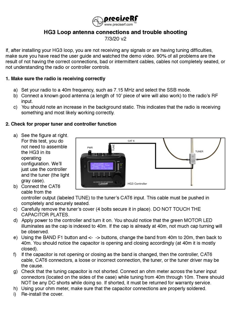
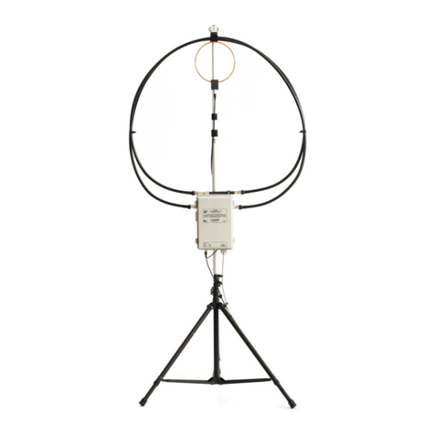
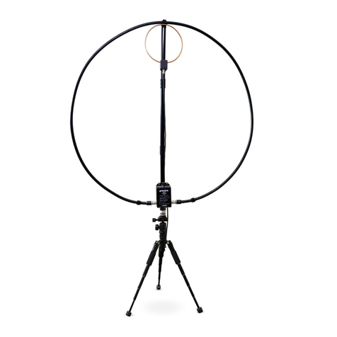
PreciseRF HG3-plus EXPRESS User manual

User Manual
For the HG3-plus EXPRESS, PRO and QRO models
Magnetic Loop Antenna
Roger M. Stenbock W1RMS

© 2021 preciserf all rights reserved Page 1 of 57

© 2021 preciserf all rights reserved Page 2 of 57
1CONTENTS
2 TERMS AND CONDITIONS .................................................................5
2.1 15 DAY PRODUCT RETURN POLICY ...........................................5
2.2 WARRANTY................................................................................6
2.3 CERTIFICATION..........................................................................6
2.4 SERVICE .....................................................................................6
2.5 REMEDIES..................................................................................6
2.6 LICENSES....................................................................................6
2.7 GENERAL SAFETY INFORMATION..............................................7
3 INTRODUCTION.................................................................................8
3.1 TUNED CIRCUIT RADIATION......................................................9
3.2 MINIMIZING LOSSES..................................................................9
3.3 DIRECTIVITY...............................................................................9
3.4 CONVENIENT.............................................................................9
3.5 LOW NOISE..............................................................................10
3.6 EFFICIENCY ..............................................................................10
3.7 LIMITATIONS ...........................................................................10
3.8 NARROW BANDWIDTH ...........................................................10
3.9 CAPACITOR VOLTAGE..............................................................11
4 HG3 PLUS MODELS..........................................................................12
4.1 EXPRESS MODEL......................................................................12
4.2 PRO MODEL.............................................................................12
4.3 QRO MODEL............................................................................12
5 ASSEMBLY AND DEPLOYMENT........................................................13
5.1 THE MAST................................................................................13
6 CONNECTIONS.................................................................................15

© 2021 preciserf all rights reserved Page 3 of 57
6.1 CONTROLLER CONNECTIONS ..................................................15
6.2 RF INTERCONNECTIONS..........................................................16
6.3 CONNECTING THE EXPRESS AND PRO ....................................16
6.4 CONNECTING THE HIGH POWER QRO ....................................17
7 CONTROLS.......................................................................................19
7.1 FRONT PANEL..........................................................................19
8 OPERATION - EXPRESS AND PRO ....................................................20
8.1 INITIALIZING THE TUNER.........................................................20
8.2 THE HOME PAGE.....................................................................21
8.3 BAND SELECTION ....................................................................21
8.4 MODE......................................................................................22
8.5 HELP ........................................................................................22
8.6 TUNING FOR MAXIMUM NOISE..............................................22
8.7 CHECKING THE SWR................................................................22
8.8 AUTO-TUNING PRO MODEL ONLY..........................................23
8.9 THE SWR BAR GRAPH..............................................................24
8.10 80 AND 60 METER TUNING.....................................................25
9 THE AR-1 ROTOR.............................................................................26
9.1 TURNING THE AR-1 ROTOR.....................................................27
10 OPERATION –QRO HIGH POWER ...................................................28
10.1 COMPONENTS.........................................................................28
10.2 PERMANENT AND PORTABLE MOUNTING CONSIDERATIONS28
10.3 ATTACHING THE HG3 QRO TUNER CASE TO THE MAST .........28
10.4 INITIALIZING THE TUNER.........................................................29
10.5 THE HOME PAGE.....................................................................30
10.6 BAND SELECTION ....................................................................30
10.7 FACTORY DEFAULT BANDS......................................................31

© 2021 preciserf all rights reserved Page 4 of 57
10.8 USER BANDS............................................................................31
10.9 TUNING WITH A LINEAR AMPLIFIER CONNECTED ..................32
10.10 TUNING FOR MAXIMUM NOISE..............................................32
10.11 CHECKING THE SWR................................................................33
10.12 AUTO-TUNING FOR LOW SWR................................................33
10.13 THE SWR BAR GRAPH..............................................................35
11 IN CASE OF DIFFICULTY ...................................................................36
11.1 CONFIRM THE RADIO IS RECEIVING........................................36
11.2 CONTROLLER CHECK - EXPRESS AND PRO MODEL .................36
11.3 CONTROLLER CHECK - QRO MODEL........................................37
11.4 MANUALLY RESETTING THE VACUUM CAPACITOR ................38
11.5 RF LOOP CONNECTIONS CHECK..............................................38
11.6 AUTO TUNE CHECK - PRO MODELS.........................................39
11.7 AUTO TUNE CHECK –QRO MODEL .........................................41
12 TUNING TIPS....................................................................................43
13 PRECAUTIONS .................................................................................44
14 SPECIFICATIONS ..............................................................................45
15 REFERENCE......................................................................................46
15.1 SCHEMATICS............................................................................46
15.2 BILL OF MATERIAL...................................................................50
16 CIRCUIT DESCRIPTION.....................................................................51
16.1 STEPPER MOTOR.....................................................................51
16.2 AR1 ANTENNA ROTATOR ........................................................52
16.3 SWR BRIDGE............................................................................53
16.4 FIRMWARE ..............................................................................53

© 2021 preciserf all rights reserved Page 5 of 57
2TERMS AND CONDITIONS
The information contained in this document is subject to change without notice.
PreciseRF makes no warranty of any kind with regard to this material, including but
not limited to the implied warranties of merchantability and fitness for a particular
purpose. PreciseRF shall not be liable for errors contained herein or for incidental or
consequential damages in connection with the furnishing, performance, or use of this
material.
2.1 15 DAY PRODUCT RETURN POLICY
1) PreciseRF factory assembled products and unassembled kits may be
returned within 15 days after the date of shipment, subject to a restocking
fee. If you have problems getting your PreciseRF kit to work, our support
team will assist you. Contact us at preciserf.com for spare or missing parts.
You can also reach us by phone at (503) 915-2490 Monday through Friday
from 9:00 am to 4:00 pm PST.
2) Products must be returned in new and unused condition in their original
packaging to qualify for a refund. On kits, all kit part’s bags must be
unopened, and the product manuals and boxes must be in a new,
undamaged state. Note: Partially built and completed kits may not be
returned for credit. PreciseRF reserves the right to make the final
determination of returned product condition. Any refunds will be less the
original shipping charges from PreciseRF to the customer. We also charge a
15% restocking fee on each returned product. The restocking fee is higher
for assembled to order products. If a product arrives in a damaged state, we
will either charge a higher return fee or return it to the customer.
3) You must contact PreciseRF for a return authorization form, instructions,
and return address before returning any products. You will be responsible
for paying for your own shipping costs for returning items. If you are
returning an item, you should consider using a trackable shipping service or
purchasing shipping insurance. We do not guarantee that we will receive the
item that you are returning. Shipping costs are non-refundable. If you
receive a refund, the cost of return shipping will be deducted from your
refund. Email preciseRF.com or call (503) 915-2490 to authorize a return or
if you have any questions.
4) Late or missing refunds. If you haven’t received a refund, please contact
your credit card company or financial institution. Your refund may take
some time before it is posted to your account. If you still have not received
your refund after contacting your financial institution or credit card
company, please contact us at preciseRF.com.

© 2021 preciserf all rights reserved Page 6 of 57
2.2 WARRANTY
The material contained in this document is provided “as is,” and is subject to being
changed, without notice, in future editions. Further, to the maximum extent
permitted by applicable law, PreciseRF disclaims all warranties, either expressed or
implied, with regard to this document and any information contained herein,
including, but not limited to, the implied warranties of merchantability and fitness for
a particular purpose.
The basic term of the warranty is twelve calendar months from the date of purchase.
The duration and conditions of warranty for this product may be superseded when
the product is integrated into (becomes a part of) other PreciseRF products. During
the warranty period, PreciseRF will, at its option, either repair or replace products
which prove to be defective. The warranty period begins on the date of delivery or
on the date of installation, if installed by PreciseRF.
2.3 CERTIFICATION
PreciseRF certifies that this product met its published specifications at the time of
shipment. PreciseRF further certifies that its calibration was accomplished with
products in accordance with industry acceptable measurement and testing practices.
2.4 SERVICE
For warranty service or repair, this product must be returned to a service facility
designated by PreciseRF. For products returned to PreciseRF for warranty service, the
Buyer shall pre-pay shipping charges and PreciseRF shall pay shipping charges to
return the product to the Buyer. However, the Buyer shall pay all shipping charges,
duties, and taxes for products returned to PreciseRF from another country.
2.5 REMEDIES
To the extent allowed by local law, the remedies provided herein are the Buyer’s sole
and exclusive remedies. PreciseRF shall not be liable for any direct, indirect, special,
incidental, or consequential damages (including lost profit or data), whether based
on warranty, contract, tort, or any other legal theory. CAUTION! DAMAGE
RESULTING FROM MISUSE, EXCESSIVE LOAD, WATER INCURSION AND USER
FIRMWARE UPDATES, IS NOT COVERED BY THE WARRANTY.
2.6 LICENSES
The hardware and/or software described in this document are furnished under a
license and may be used or copied only in accordance with the terms of such license.
All rights are reserved. Reproduction, adaptation, or translation without prior written
permission is prohibited, except as allowed under the copyright laws.

© 2021 preciserf all rights reserved Page 7 of 57
2.7 GENERAL SAFETY INFORMATION
Do not operate the product in an explosive atmosphere or in the presence of
flammable gasses or fumes. For continued protection against fire, replace any fuse
with the same voltage and current rating and type.
Do not perform procedures involving cover or shield removal unless you are qualified
to do so. Procedures involving the removal of covers and shields are for use by
service-trained personnel only.
Do not service or adjust the product alone. Under certain conditions, dangerous
voltages may exist, even with the product switched off. Do not operate damaged
products. Whenever it is possible that the safety protection features built into this
product have been impaired, either through physical damage, excessive moisture, or
any other reason, REMOVE POWER and do not use the product until safe operation
can be verified by service-trained personnel. If necessary, return the product to
PreciseRF for service and repair to ensure the safety features are maintained.
Do not substitute parts or modify the product. Because of the danger of introducing
additional hazards, do not install substitute parts or perform any unauthorized
modification to the product. For service, return the product to PreciseRF.

© 2021 preciserf all rights reserved Page 8 of 57
3INTRODUCTION
This manual covers the operation, description, and care of the preciseRF HG3
EXPRESS, PRO and QRO Magnetic Loop Antennas (MLA). It was created for
amateur radio, military, and HF operators wanting the performance
advantages of an MLA without its drawbacks.
This manual assumes a rudimentary understanding of radio and electronics
typically acquired by amateur radio operators. For brevity, the HG3 is
referred to as the HG3 EXPRESS, PRO or QRO in this manual.
A magnet loop is not a new antenna. What sets the HG3 MLA apart is how it
addresses many of the magnetic loop antenna’s shortcomings. The result is
the HG3 MLA. It delivers unprecedented capability, performance, and
convenience for a remotely tuned MLA. It uses a proven, accurate and
repeatable stepper motor design. Band selection, remote tuning, including
optional loop rotation, is controlled by a microcontroller driving a high-
resolution stepper motor. An integrated digital SWR bridge allows auto-
tuning based on an SWR scan. This ensures compatibility with most radios.
Manual tuning uses a convenient rotary encoder knob - no more finicky push
buttons. The four-line LCD shows the band selected, SWR, ERP, capacitor
value and more. The bottom line - count on topnotch receiving and
transmitting performance!

© 2021 preciserf all rights reserved Page 9 of 57
3.1 TUNED CIRCUIT RADIATION
An MLA is just an inductor formed by a wire loop with a circumference
limited to less than 10% of a wavelength and a capacitor in parallel tuned to
resonance.
Electrically, it behaves as an inductor
that inductively couples the radio wave
(electromagnetic wave) magnetic field
in the antenna’s near region. In
contrast, conventional monopole, and
dipole antennas couple to the radio
wave’s electric field.
3.2 MINIMIZING LOSSES
To work efficiently, losses must be
minimized. Because of skin effect, the
inductor forming the radiation loop’s (L)
surface area should be high. This decreases series resistive losses. The tuning
capacitor (C) should have a low loss dielectric for low Equivalent Series
Resistance (ESR). This LC circuit must be tuned to resonance at the desired
frequency. At resonance, the MLA exhibits very high Q. As a result, it exhibits
very narrow bandwidth and high voltage (in the kilovolts) across the
capacitor.
3.3 DIRECTIVITY
The MLA has its maximum signal gain in
the plane of its radiation loop, with
nulls broadside to the loop.
3.4 CONVENIENT
It is a compact, lightweight efficient
antenna that's quickly deployable. It is
ideal where an HOA restricts full-size
wire antennas, or where there just is
not enough room to erect a
conventional antenna. Many operators
favor the MLA for Field Day and Summit On The Air (SOTA) operations.
Figure 1 Magnetic Loop Antenna
Figure 2 Directivity

© 2021 preciserf all rights reserved Page 10 of 57
3.5 LOW NOISE
The MLA rejects locally generated
background noise noise due to its
inherent magnetic field coupling and
its relative insensitivity to the electric
field. That's valuable. Most
interference sources with RF content,
directly radiate in the near electric
fields. That's a big advantage for using
an antenna that's insensitive to the
main interference sources present in
that frequency range.
3.6 EFFICIENCY
When designed and constructed
properly, an MLA performs as well or
even better than a dipole antenna.
According to the American Radio Relay
League (ARRL) technical editor, Jerry
Hall K1TD, in describing MLA gain,
concluded: “…in fact, it (MLA)
considerably exceeds the gain of a
dipole when the MLA is mounted close
to the ground.”
3.7 LIMITATIONS
An MLA is not for every application and not for everyone. First, while
desirable for selectivity and background noise rejection (note the loop’s
excellent Return Loss and SWR characteristics below) it can be challenging.
3.8 NARROW BANDWIDTH
Because of this narrow bandwidth, it must be retuned when making any
significant frequency changes. This was especially annoying with first-
generation tuning control methods. They lacked a clear indication of the
tuning capacitor position, quick band switching and convenient incremental
tuning. So, it is not recommended for quick band scanning, unless the MLA
has addressed these shortcomings. Fortunately, the HG3 MLA was designed
Figure 3 Near Field Radiation
Figure 4 Dipole V Loop Radiation

© 2021 preciserf all rights reserved Page 11 of 57
to overcome most of these limitations.
3.9 CAPACITOR VOLTAGE
The capacitor is at a high voltage ranging in the kilovolts. It is at high
impedance and can’t deliver much current, so any contact will load it and
rapidly reduce the voltage. There is still enough charge stored in the tuning
capacitor to cause an RF-burn. At higher power settings, the tuning capacitor
can break down and cause arcing. For that reason, high power operation
requires a special and more costly capacitor, such as a vacuum dielectric
capacitor.
Figure 5 Hi Q of Loop Antenna

© 2021 preciserf all rights reserved Page 12 of 57
4HG3 PLUS MODELS
The HG3 plus controller supports the EXPRESS, PRO and QRO models with the
capability of additional options. (* See section 14 SPECIFICATIONS for greater
detail.)
EXPRESS
PRO
QRO
Resolution BW
13.5 KHz
13.5 KHz
600 Hz
Max Power*
100W
100W
1,500W
Bands*
40-10 meter
80-10 meter
80-10 meter
Tuning
Manual
Manual Auto
Manual Auto
SWR Bridge
No
YES
YES
Antenna Rotor
No
YES
YES
4.1 EXPRESS MODEL
The EXPRESS model is the basic model. It supports a high resolution 2000-
step stepper motor and manual tuning.
4.2 PRO MODEL
The Pro model supports a high resolution 2000-step stepper motor, manual
tuning, external resonator, auto-tuning, antenna rotation and includes the
integrated SWR bridge and ERP functions.
4.3 QRO MODEL
This QRO model is our premium antenna. It uses a 45,000-step stepper motor
to drive a vacuum capacitor. Its output shaft is connected to the vacuum
capacitor via a 5:1 planetary gear. This provides increased torque, very low
backlash, and excellent resolution.
The controller needs to be indexed to a known capacitance (step) of the
vacuum capacitor in order to tune the MLA to the desired band and
resonance. Traditionally, limit switches were used to detect that position.
Because of the required gear train, they introduced additional backlash and
complexity. The HG3 MLA uses optical sensors to detect the index position.
Initializing, if required, needs only be done when the controller is turned on.

© 2021 preciserf all rights reserved Page 13 of 57
This allows for user programable band selection, RapidTune™AUTO tuning
and full power operation at 80 meters.
5ASSEMBLY AND DEPLOYMENT
5.1 THE MAST
Proper deployment is crucial for any antenna,
especially for an MLA. Begin with the mast and
tuner. Follow these steps:
1) Find a level surface clear of any obstructions
within an approximate 25-foot radius and
extend your tripod to a convenient height.
Use either the supplied tripod or your own.
The MLA works well from two feet or higher
above the ground. After approximately a six-
to-ten-foot height, little performance is
gained.
2) Assemble the mast. The HG3 is available
with either an optional aluminum or PVC
mast. When properly guyed, the aluminum
mast is suitable for more permanent
deployment. When using the aluminum
mast, other than attaching the tuner and
placing it on the tripod, no further mast
assembly is required.
3) The PVC mast is made up of three sections.
It's intended for portable use. It should
never be left unattended. It takes just slight
pressure to fit the mast sections securely
together. The tuner attaches to the lower
section, which attaches to the center
section. The center section attaches to the
top section. The top section includes the induction loop.
4) Note, this step applies to the AR1 Antenna Rotator only. When using the
optional AR1 Antenna Rotator, its base must first be securely attached to
Figure 7 Induction Loop
Figure 6 The PVC Mast

© 2021 preciserf all rights reserved Page 14 of 57
the tripod using the tripod adaptor. Then thread the mast onto the
rotator's output shaft.
5) Spread the radiation loop and fit it to the top
of the mast using the snap clamps. Orient the
induction loop to face forward over the
radiation loop. Locate the tuner and attach it
to the mast’s lower section using the supplied
hardware. Next, securely thread the PL239
connectors, located at the radiation loop's
ends, onto the tuner's SO239 input
connectors. Connect the supplied 50 Ω
coaxial cable to the induction loop BNC
connector.
6) Connect the other end of the 50 Ω coaxial
cable to the radio’s input/output for the EXPRESS model or to the
controller as described for the PRO model.
7) NOTE: TRIPOD USE IS
INTENDED FOR
TEMPORARY PORTABLE
DEPLOYMENT ONLY. IT
MUST BE GUYED! For a
more secure
installation, clamp the
mast to a solid object,
such as a TV antenna
mast. Use U bolts,
available at most
hardware stores.
8) Locate the antenna at
least 25 feet from the controller and people. CAUTION: The antenna’s
radiator is at a high voltage level and emits a high RF field.
Figure 8 U Bolts
Figure 9 Recommended 25-foot Distance

© 2021 preciserf all rights reserved Page 15 of 57
6CONNECTIONS
6.1 CONTROLLER CONNECTIONS
The HG3 plus controller is compatible with the EXPRESS, PRO and QRO
remotely tuned MLAs. Not all connections may be used. Refer to the figure:
CONNECTOR
PURPOSE
12-14 VDC input
Power input. Ensure it has adequate voltage
and current for the model in use.
TUNER
CAT6 controller cable to the loop tuner for
the EXPRESS and PRO model.
USB
Factory used only for programming.
ROTATOR
CAT6 cable to control the AR1 Rotator.
QRO tuner
DB9 controller cable to the loop tuner for
the QRO model.
RF output
RF output for antenna or to drive an
external linear amplifier.
RF input
RF input from the transceiver.
Figure 10 Rear Connections

© 2021 preciserf all rights reserved Page 16 of 57
6.2 RF INTERCONNECTIONS
Depending on the model and your setup, the RF output from your HF radio
will loop though the HG3 plus controller to be used to reference the SWR
during tuning operations. Normal tuning is done using AM/CW modes
between 1 and 5 Watts. Normal operational power is up to 100 Watts
maximum. The RF output will then drive your linear amplifier or MLA
antenna. Use only quality 50 Ω interconnect cables.
6.3 CONNECTING THE EXPRESS AND PRO
The MLA can be manually tuned. For manual tuning, connect the transceiver
RF directly to the tuner and the controller to the tuner. See below:
When automatic tuning is desired, the transceiver’s RF output must be
connected to the controller’s RF INPUT and the controller’s RF OUTPUT
connects directly to the tuner. See below:
RF
TRANCEIVER
CAT 6 CONTROLLER CABLE
HG3 PLUS CONTROLLER
IND LOOP
REMOTE
TUNER
Figure 11 EXPRESS Model Connections

© 2021 preciserf all rights reserved Page 17 of 57
6.4 CONNECTING THE HIGH POWER QRO
The MLA can be manually tuned. For manual tuning, connect the transceiver
RF directly to the linear amplifier’s RF input and the controller to the tuner.
Connect the linear amplifier’s RF output directly to the REMOTE TUNER
SO239 input. See below:
RF
TRANCEIVER
CAT 6 CONTROLLER CABLE
HG3 PLUS CONTROLLER
RF IN
RF OUT
TUNER
REMOTE
TUNER
Figure 12 PRO Model Connections
RF
CONTROLLER
TRANCEIVER
DB-9 CONTROLLER CABLE
HG3 PLUS CONTROLLER
IND LOOP
RF IN
RF OUT
LINEAR AMP
OUT
Figure 13 QRO High Power - Manual Tune
QRO TUNER

© 2021 preciserf all rights reserved Page 18 of 57
When automatic tuning is desired, the transceiver’s RF output must be
connected to the controller’s RF INPUT and the controller’s RF OUTPUT
connects directly to the linear amplifier’s RF input. Connect the linear
amplifier’s output directly to the REMOTE TUNER SO239 input. See below:
RF
CONTROLLER
TRANCEIVER
DB-9 CONTROLLER CABLE
HG3 PLUS CONTROLLER
IND LOOP
RF IN
RF OUT
RF IN
RF OUT
LINEAR AMP
OUT
QRO TUNER
Figure 14 QRO High Power - Auto Tune

© 2021 preciserf all rights reserved Page 19 of 57
7CONTROLS
7.1 FRONT PANEL
Remote loop tuning, band selection and the usual setup procedure are
accomplished via the front panel controls. The LCD provide the current tuning
and performance status at a glance. See the figure below:
CONTROL
PURPOSE
Power switch
The power switch turns the controller on/off. Most
operators use their shack’s 13.5V power supply. For
the EXPRESS and PRO models, a common 9 VDC 200
mA will work well. The QRO model requires more
power because of the vacuum capacitor. It requires
12.5 to 14.5 volts at a maximum current of 1,500 mA
when tuning and 200mA when at idle.
Function keys
The F1 to F4 keys are soft keys which change functions
based on the required operation.
Tuning knob
The encoder knob is used to adjust the tuning for best
SWR. The mechanical detents do not necessarily
represent the encoded pulses. Pushing the knob in
toggles it between normal and fine sensitivity. The
FINE LED indicates its status.
SWR
bar graph
The ten segment, green, yellow, and red segment bar
graph is not calibrated. It provides only a relative
indication of the SWR during tuning when used with
power levels from 1 to 5 Watts. Any level in the green
segment range is acceptable.
Figure 13 Front Panel
This manual suits for next models
2
Table of contents
Other PreciseRF Antenna manuals
Popular Antenna manuals by other brands

One Forall
One Forall SV-9320 instruction manual

Self-Sat
Self-Sat SNIPE PLATINUM user manual
Butternut
Butternut HF5B instruction manual

Feig Electronic
Feig Electronic OBID ID RW24-A manual

Crestron
Crestron Antenna System SRD-ANT-1LD-PAK installation guide
Siemens
Siemens SIMATIC NET ANT795-6MN Compact operating instructions
