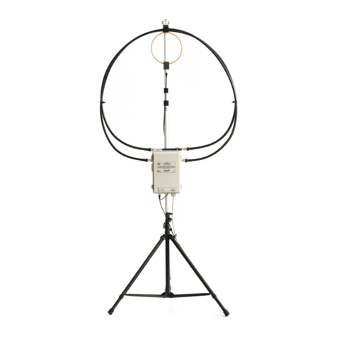
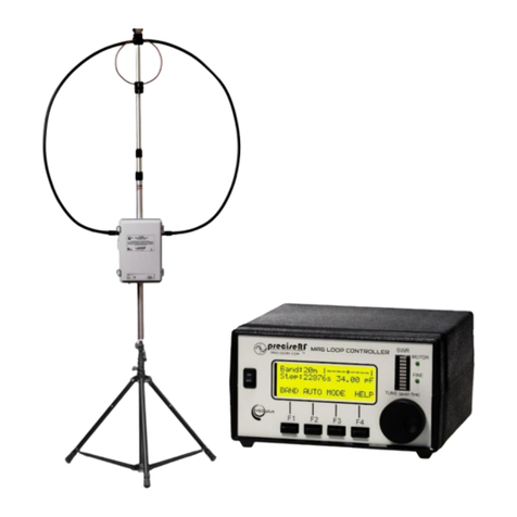
PreciseRF PreciseLOOP HG-1 Deluxe User manual

1
PreciseLOOP® Antennas
V4.2 6-15-2019
Manual Tuned Magnetic Loop Antennas (MLA)
The HG-1 Deluxe, HG-1 Express and SOTA-1 are all manual tuned MLAs. They are designed for quick deployment.
Except for feature differences they all set up the same. The process takes under five minutes. Always check
www.preciserf.com for the latest version.
ASSEMBLY
1. Find a level surface that is clear of any obstructions within
approximately a 15-foot radius. Use either the supplied
tripod or use your own. Extend your tripod to a convenient
height. The PreciseLOOP® will work well from two feet or
higher above the ground. After approximately a 6-10 foot
height little is gained in performance.
2. Assemble the antenna mast. It consists of three sections.
The lower section contains the tuner, the center section
connects the lower and the top section and the top section
contains the induction loop. All it takes is slight pressure to
fit the mast sections securely together. Attach the optional
tripod adaptor to the antenna mast.
3. Attach the tuner to the lower mast section using the
supplied bolts. Mount the mast to the tripod’s standard 25
mm socket.
4. Spread the radiation loop and fit to the top of the mast.
Make sure the induction loop is facing toward the front
over the radiation loop. Securely attached PL239
connectors to the tuner inputs.
5. Connect the 12-foot, 50-ohm BNC cable, from the induction loop output the transceivers antenna
input. Adjust the loop assembly for a symmetrical appearance.
TUNING
1. Tuning instructions are also printed on the tuning
enclosure, refer to them as well.
2. Select the band you wish to use. Set the transceiver to
SSB (this provides the loudest background noise).
3. Adjust the loop tuner for maximum received noise or
signal (do not use a tuner). Rotate the loop in line with

2
the desired direction. Maximum gain is approximately +20dB over the minimum direction. (see
illustration at right).
4. Transmit a low power (1 W) CW signal and adjust the loop tuner for minimum SWR. If needed, use
a tuner or auto tuner to get the VSWR to minimum. This will take a little practice because an MLA
has very sharp tuning characteristics.
5. You can make fine SWR adjustment by sliding the induction loop up or down about 1/4 inch.
6. Once you achieve an SWR of 2.0 or less, you’re ready for a QSO.
7. Repeat these steps when QSY.
CAUTION: THE LOOP CONNECTORS ARE AT HIGH VOLTAGE WHEN TRANSMITTING. DO NOT
EXCEED THE MAXIMUM POWER RATING.
HG-1 REMOTE TUNER
Retrofit - replaces knob
There are currently two remote tuning options. They are the HG-1 Remote option (retrofit replaces the knob)
and HG-1 WR Remote Tuner Resonator. They both share a common HG-2 Controller. This controller provides
unique indications of CCW & CW limits depending on the remote used. Each will be explained below.
THE HG-1 REMOTE TUNER (retrofit)
The HG-1 REMOTE TUNER is a compact, easy-to-use tuner for an MLA. It is designed specifically as a retrofit for
the popular preciseRF HG-1 MLA. You can place your HG-1 MLA at a remote location, such as the top of your RV,
away from obstructions, for better radiation efficiency and less interference. The controller features an efficient,
low noise, pulse-width modulated, motor controller. The drive motor RPM RATE is adjustable over a very wide
range. This allows for precise tuning and low SWR.
A custom designed current limiter detects the end of the tuning range and alerts the operator when the tuning
limit is reached by a red LED limit indicator. In addition, a failsafe slip clutch mechanism protects the motor and
tuning capacitor as well. Note: Always use a fresh 9V Battery or the optional power supply. Any supplied battery
may be partially depleted.

3
While you may get a green power light indication (SBY), there may not be sufficient battery power to run the
motor. We suggest for long term operation use the optional Universal Power Supply 9VDC available from
preciseRF.
INSTALLING THE HG-1 MOTOR DRIVE ASSEMBLY.
1. Open the existing HG-1 manual tuner case. (Refer to the
figure). Take care not to damage the tuning capacitor by
setting the frequency to its lowest setting.
2. Remove the existing knob and pointer (save them for
potential future use).
3. Remove the existing mounting screws securing the 6:1
reduction drive (save any spacers or nuts).
4. Remove the temporary nuts securing the two spacers
attached to the HG-1 motor assembly.
5. Attach the HG-1 motor assembly to the capacitor shaft.
6. Using the supplied longer #4-40 screws, mount the HG-1
motor assembly to the 6:1 reduction drive.
7. Tighten the set-screws and reinstall the HG-1 manual tuner
case back.
ADJUST THE TORQUES SENSOR AND REPLACING THE BATTERY (applies
the HG-1 REMOTE TUNER retrofit only)
The red LED limit indicator illuminates when the capacitor has
reached the CW and CCW position. Because there is some
variation in 6:1 reduction drive torque, the sensor can be
calibrated.
1. Refer to the figure. Open the back of the remote controller case by removing the four screws. Note
the blue miniature potentiometer located on the interface board.
2. Set the RATE to MAX. While pressing the UP and Down buttons adjust the blue potentiometer such
that the red LED limit indicator illuminates brightly when the capacitor reaches the CW and CCW
ends. It is normal for the red LED limit indicator to flicker occasionally. (You may have to repeat this
adjustment as the 6:1 reduction drive loosens over time).
3. The battery may also be replaced at this time. Battery life depend on type and use. Generally, it
should last for an extended tuning session. Turn the remote off when not in use.
4. Replace the back cover of the remote controller being careful not to pinch any of the wires.

4
DEPLOYING THE HG-1 REMOTE TUNER
1. Make sure the HG-1 Magnetic Loop antenna is placed in an obstruction free area.
2. For better water protection, the HG-1 motor drive assembly may be mounted facing down.
3. Connect both ends of the supplied cable (common CAT6 Ethernet cable) to the motor assembly and
controller.
4. Turn the HG-1 Remote Tuner on; the green SBY LED should illuminate.
5. Set the Rate control to its Max position.
6. While observing the motor assembly, push the red Up or green Down buttons. Note the motor
turning CCW or CW depending on the button pushed. This is an indication that the system is
correctly connected and everything is in order. If the red LED limit indicator comes on, that is also
OK. It just means you have reached the limits of the tuning range.
TUNING WITH THE HG-2 CONTROLLER (HG-1 Remote Tuner Retrofit)
1. If possible, turn the receiver’s AGC off or set it to slow; bypass any external or automatic antenna
tuner and set the mode to SSB (it’s has the loudest background noise).
2. Turn the HG-1 Remote Controller to SBY (on) and set
the Rate control to Max.
3. Note: Applies to HG-1 Remote only. There are no limit
switches on the Remote tuner. The HG-2 Controller
samples the motor current.
4. Using the red Up or green Down buttons, tune for a
peak receive signal (use your ears or the S meter). The
maximum peak will be brief, but obvious. You may have to momentarily push the Up or Down
buttons to get close. (The red LED limit indicator lights if either the lower or upper limits are reached
–slight flickering is normal).
5. Once you receive an obvious peak signal, reduce the RATE control and alternately make small
adjustments using the UP or DOWN buttons for the strongest peak signal.
6. Note, when checking SWR, transmit a low power carrier. You should be able to achieve an SWR of
2:1 or better. In rare cases, you may want to use an external tuner to touch up the SWR.
7. Set the receiver to the desired mode and turn the HG-2 Remote Controller off.
When the capacitor reaches its CW or CCW
limits, the red LED limit indicator turns on
bright, indicating you have reached the end of
capacitor rotation limits, thus alerting the
operator to change tuning directions. (The silk-
screened markings do apply).

5
HG-1 WR REMOTE LOOP TUNED MLA
Outdoor deployable
This remote is designed for harsher outdoor and fixed installations. It is
a durable, easy-to-use, remote tuner upgrade to your existing HG-1 MLA
using its radiation and induction loops and mast. It features end-of-cap
travel limit switches for long life. It uses the new HG-2 universal
controller. To maximize reliability found in the harsher environmental
conditions outdoors, this remote tuner uses a lower RPM motor and no
reduction gear. For this reason, there is a shallow learning curve to get
used to remote tuning. SWR is as low as the manually tuned HD-1 which
uses the identical tuning capacitor. We recommend, for convenient and
quick tuning to lowest SWR, using an auto tuner, such as those found in
the KX2 or similar transceivers.
TUNING WITH THE HG-2 CONTROLLER (HG-1 WR Remote Tuner)
1. Make sure the HG-1 MLA is placed in an obstruction free
area.
2. Connect both ends of the supplied cable (common CAT-6
cable) to the motor assembly and controller.
3. If possible, turn the receiver AGC off or set it to slow; bypass
any external or automatic antenna tuner and set the mode to
CW (it has the lowest controller QRM noise).
4. Note: Applies to HG-1 WR REMOTE LOOP TUNER. The HG-1
WR uses limit switches. So current sampling is used to
indicate the motor is powered on. CW and CCW limits are
indicated when the red LED limit indicator extinguishes.
5. Turn the HG-2 Remote Controller to SBY (on)
and set the RATE control to a mid-range setting.
6. Using the red UP or green DOWN buttons, tune
for a peak receive signal (use your ears or the S
meter). The maximum peak will be brief, but
obvious. You may have to momentarily push the
UP or DOWN buttons to get close.
7. Once you receive an obvious peak signal, reduce the Rate control to about 1/3 and alternately make
small adjustments by briefly tapping the Up or Down buttons for the strongest peak signal.
8. Note, when checking SWR, transmit a low power carrier. You should be able to achieve an SWR of 3:1 or
better. Once you achieve 3:1 or better, use an external or built-in auto tuner to touch up the SWR. You
should easily achieve an SWR of 1:1.5 or better.
9. Set the receiver to the desired mode and turn the HG-2 Remote Controller off.
The red LED limit indicator will stay on
indicating the motor is powered during
capacitor turning and turn off when reaching
the CCW or CW limits, alerting the operator to
change tuning direction (The silk-screened
markings do not apply).

6
HG-1 WR 80M AND 60M OPERATION
The HG-1WR is capable for 60m and 80m operation. Because of performance optimization circuit boards with
isolation jumpers are used to connect external the 60m and 80m resonators. These circuit boards are mounted
on each side of the case. See figure below.
These boards are identical. On these boards there is a solder jumper labeled 60/80M JUMPER JP1. See figure
below:
These jumpers isolate the banana jack inputs and must be bridged. For 60/80-meter operation create a solder
bridge on both boards. Heat the pads and apply sufficient solder to bridge the pads.
The Banana jacks are mounted on the top of the case and are water resistant. The external resonator can be
inserted approximately 2/3 into the jacks and will fit securely.
Tuning is done with the main resonating tuning capacitor as in 40-10-meter operation.
DIFFERENCES BETWEEN MANUAL AND REMOTE TUNING
When tuning manually the operator tunes for a peak receiver signal by rapidly turning a knob and listening for a
peak receive signal after which he then makes small adjustments to fine tune and to achieve the lowest SWR.
Because of AGC action, if you were to initially tune slowly, you might never notice the increased noise level
indicating a peak signal. Tuning with a remote controller is different. The operator sets the tuning rate and then
pushes either the up (red) or down (green) buttons to tune. Initially the tuning rate should be set fast to detect
a peak, after which the tuning rate is lowered to fine tune for best SWR. This takes a little practice at first. The
benefit is that your hand will not affect the tuning capacitor, and you can do this remotely without touching the
MLA itself.
This manual suits for next models
2
Table of contents
Other PreciseRF Antenna manuals
Popular Antenna manuals by other brands
TracVision
TracVision Track Vision M9 manual
RF Elements
RF Elements UltraDish UD-TP-21 manual
Panorama Antennas
Panorama Antennas GPSC Series Installation instruction
KVH Industries
KVH Industries TracVision R5 installation guide

Maxview
Maxview CONNECT MXL028/65Q Installation, Satellite Information & Fault Finding

Sirio Antenne
Sirio Antenne MAG 45/135 installation manual

