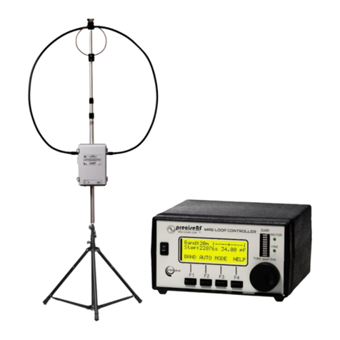
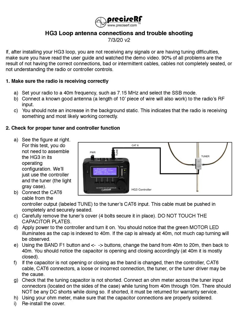
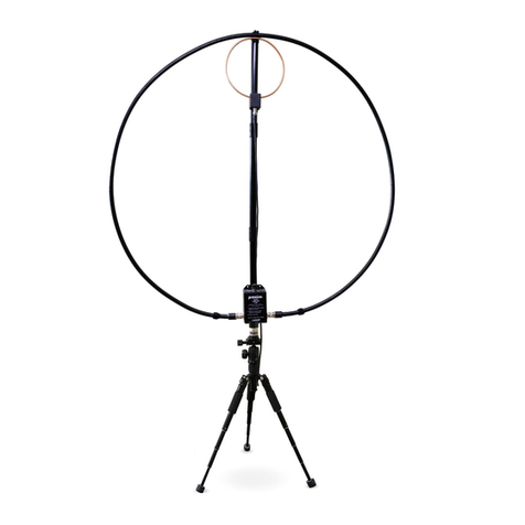
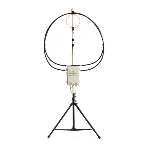
PreciseRF HG3 User manual

HG3 STEPPER MAG LOOP™
REMOTELY TUNED HF MAGNETIC LOOP ANTENNA
USER GU I D E

TABLE OF CONTENTS
INTRODUCTION!3
DESCRIPTION!4
CHARACTERISTICS!5
DEPLOYMENT!7
CONTROLLER!9
CONNECTIONS!11
CONNECTIONS - EXPRESS MODEL!11
STARTUP - ALL VERSIONS!12
TUNING FOR MAXIMUM NOISE - EXPRESS MODEL!13
CHECKING THE SWR - EXPRESS MODEL!14
CONNECTIONS - PRO AND LAB OPTIONS!15
TUNING FOR MAXIMUM NOISE - PRO AND LAB MODEL!15
AUTO TUNING FOR LOW SWR - PRO AND LAB MODELS!16
TUNING TIPS!18
80 AND 60 METER TUNING!19
THE AR-1 ROTOR!20
TURNING THE AR-1 ROTOR!20
PRECAUTIONS!21
SPECIFICATIONS!22
SYSTEM REFERENCE!23
CIRCUIT DESCRIPTION!24
______________________________________________________________
____________________________________________________________________________
User Guide HG3 Stepper Mag Loop V1.2 © preciseRF - page 2

INTRODUCTION
This manual covers the operation, description and care of the
preciseRF HG3 Stepper Mag Loop Antenna. It was created for
the amateur radio, military, and HF operator wanting the
performance advantages of an MLA without some of its
drawbacks. This manual assumes a rudimentary understanding
of radio and electronics. For brevity, the HG3 stepper tuned Mag
Loop Antenna (MLA) is referred to as the HG3 MLA in this
manual.
A magnet loop is not a new antenna. What sets the HG3 MLA
apart is how it addresses many of the magnetic loop antenna’s
shortcomings. The result is the HG3 MLA. It delivers
unprecedented capability, performance and convenience for a
remotely tuned MLA. It employs a proven, accurate and
repeatable stepper motor design.
Band selection, remote tuning, including optional loop rotation, is
controlled by a microcontroller driving a high-resolution stepper
motor. An integrated digital SWR bridge allows auto-tuning
based on an SWR scan. This ensures compatibility with most
radios. Manual tuning uses a convenient rotary encoder knob - no
more finicky push buttons. The four-line LCD shows the band
selected, SWR, ERP, Cap value and more. The bottom line -
count on topnotch receiving and transmitting performance!
______________________________________________________________
____________________________________________________________________________
User Guide HG3 Stepper Mag Loop V1.2 © preciseRF - page 3

DESCRIPTION
An MLA is just an inductor formed by a wire loop with a
circumference limited to less than 10% of a wavelength and a
capacitor tuned to resonance.
Electrically, it behaves as an
inductor that inductively couples
the radio wave (electromagnetic
wave) magnetic field in the
antenna’s near region. In contrast,
conventional monopole and dipole
antennas couple to the radio
wave’s electric field.
To work efficiently, losses must be
minimized. Because of skin effect,
the inductor forming the radiation
loop’s (L) surface area should be
high. This decreases series resistive losses. The tuning capacitor
(C), should have a low loss dielectric for low Equivalent Series
Resistance (ESR). This LC circuit must be tuned to resonance at
the desired frequency. At
resonance, the MLA exhibits
very high Q. As a result, it
exhibits very narrow
bandwidth and high voltage
(in the kilovolts) across the
capacitor.
The MLA has its maximum
signal gain in the plane of its
radiation loop, with nulls
broadside to the loop.
Fig. 1 Magnetic Loop Antenna
Fig. 2 Loop directionality
______________________________________________________________
____________________________________________________________________________
User Guide HG3 Stepper Mag Loop V1.2 © preciseRF - page 4

CHARACTERISTICS
CONVENIENCE
It is a compact, lightweight efficient antenna that's quickly
deployable. It is ideal where an HOA restricts full-size wire
antennas, or where there just is not enough room to erect a
conventional antenna. Many operators favor the MLA for field day
and SOTA (Summit On The Air) operations.
LOW NOISE
The MLA rejects locally
generated noise due to its
inherent magnetic field coupling
and its relative insensitivity to the
electric field. That's fortuitous.
Most interference sources with
radio-frequency content, directly
radiate in the near electric fields.
That's a big advantage for using
an antenna that's insensitive to
the main interference sources
present in that frequency range.
EFFICIENCY
When designed and
constructed properly, an MLA
performs as well or even better
than a dipole antenna.
According to the American
Radio Relay League (ARRL)
technical editor, Jerry Hall
K1TD, in describing MLA gain,
concluded: “in fact, it (MLA)
considerably exceeds the gain
of a dipole when the MLA is
mounted close to the ground”.
Fig. 3 Near field propagation, magnetic
field (blue) versus electric field (red)
Fig. 4 Dipole v. Mag loop radiation
patterns, note superior low angle for
loop
______________________________________________________________
____________________________________________________________________________
User Guide HG3 Stepper Mag Loop V1.2 © preciseRF - page 5

HIGH SELECTIVITY
An MLA is not for every application and not for everyone. First,
while desirable for selectivity and noise rejection (note the loop’s
excellent Return Loss and SWR characteristics below) it can be
challenging.
Because of this
narrow bandwidth,
it must be retuned
when making any
significant
frequency
changes. This was
especially
annoying with
first-generation
tuning control
methods. They
lacked a clear
indication of the tuning capacitor position, quick band switching
and convenient incremental tuning. So, it is not recommended for
quick band scanning, unless the MLA has addressed these
shortcomings. Fortunately, the preciseRF HG3 MLA was
designed to overcome some of these limitations.
CAPACITOR HIGH VOLTAGE
The capacitor is at a high voltage ranging in the kilovolts. It is at
high impedance and can’t deliver much current, so any contact
will load it and rapidly reduce the voltage. There is still enough
charge stored in the tuning capacitor to cause an RF-burn. At
higher power settings, the tuning capacitor can break down and
cause arcing. For that reason, high power operation requires a
special and more costly capacitor, such as a high voltage air
dielectric butterfly or vacuum dielectric capacitor.
Fig. 5 Excellent SWR and high Q
______________________________________________________________
____________________________________________________________________________
User Guide HG3 Stepper Mag Loop V1.2 © preciseRF - page 6

DEPLOYMENT
Proper deployment is crucial for any antenna, especially for an
MLA. Begin with the mast and tuner. Follow these steps:
1. Find a level surface clear of any obstructions within an approximate
15-foot radius.
2. Extend your tripod to a convenient height. Use either the supplied
tripod or your own. The MLA works well from two feet or higher
above the ground. After approximately a six to ten foot height, little
performance is gained.
3. Assemble the mast. The HG3 is available with either an optional
aluminum or PVC mast. When properly guyed, the aluminum mast is
suitable for more permanent deployment. When using the aluminum
mast, other than attaching the tuner
and placing it on the tripod, no further
mast assembly is required.
4. Assemble the PVC mast. The PVC mast
is made up of three sections. It's
intended for portable use. It should
never be left unattended. It takes just
slight pressure to fit the mast sections
securely together. The tuner attaches to
the lower section, which attaches to the
center section. The center section
attaches to the top section. The top
section includes the induction loop.
5. Note, this step applies to the AR1
Antenna Rotator only. When using the
optional AR1 Antenna Rotator, its base
must first be securely attached to the
tripod using the tripod adaptor. Then
thread the mast onto the rotator's
output shaft. Fig. 6 The PVC mast
______________________________________________________________
____________________________________________________________________________
User Guide HG3 Stepper Mag Loop V1.2 © preciseRF - page 7

6. Spread the radiation loop and fit it to the top of the mast using the
snap clamps. Orient the induction loop to face
forward over the radiation loop. Locate the tuner
and attach it to the mast’s lower section using
the supplied hardware. Next, securely thread
the PL239 connectors, located at the radiation
loop's ends, on to the tuner's SO239 input
connectors. Connect the supplied 50-ohm
coaxial cable to the induction loop BNC
connector.
7. Connect the other end of the 50 ohm coaxial
cable to the radio’s input/output for the
EXPRESS model or to the controller as
described for the PRO or LAB versions.
8. NOTE, TRIPOD USE IS INTENDED FOR
TEMPORARY PORTABLE DEPLOYMENT ONLY.
ITS MUST BE GUYED! For a more secure
installation, clamp the mast to a solid object,
such as a TV antenna mast as shown at right.
Use U bolts available at most hardware stores.
9. Locate the antenna at least 25 feet from the
controller and people. CAUTION: The antenna’s radiator is at a high
voltage level and emits a high RF field.
Fig. 7 Induction loop
Fig. 8 U-bolts
Fig. 9 Recommended 25 foot distance
______________________________________________________________
____________________________________________________________________________
User Guide HG3 Stepper Mag Loop V1.2 © preciseRF - page 8

CONTROLLER
The HG3 controller supports a wide range of
options. The initial offering includes the
EXPRESS, PRO and LAB options, with the
capability of additional options (see the table
below). A USB key determines which options
are installed. The controller reads the USB key
and automatically sets it to the correct option/
version on startup.
EXPRESS
PRO
LAB
QRO
Processor
Language
ATmega328
P Nano V3
C++
ATmega328
P Nano V3
C++
ATmega328
P Nano V3
C++
ATmega328P
Nano V3
C++
Stepper
Motor
28BYJ-48
Unipolar
2K Steps
28BYJ-48
Unipolar
2K Steps
NENA 17
Unipolar
8K Steps
NENA 21
Unipolar
8K Steps
Resolution
.08pF
.08pF
.02pF
.02pF
Power
Supply
9 VDC 1A
9 VDC 1A
9 VDC 1A
12 VDC 2A
Option Key
none
PRO
LAB
QRO
Manual
Tuning
√
√
√
√
Auto Assist
Tuning
√
√
√
External
Resonators
√
√
√
√
SWR Bridge
√
√
√
Antenna
Rotator
√
√
√
•EXPRESS MODEL
It is the standard model and requires no USB key. It supports
a high resolution 2000 position stepper motor, manual tuning
and an external resonator.
Fig. 10 The USB key
______________________________________________________________
____________________________________________________________________________
User Guide HG3 Stepper Mag Loop V1.2 © preciseRF - page 9

•PRO OPTION
This version requires the PRO USB key. It supports a high
resolution 2000 position stepper motor, manual tuning,
external resonator, auto-tuning, antenna rotation and includes
the integrated SWR bridge and ERP functions.
•LAB OPTION
This version requires the LAB USB key. It is intended for
advanced users wanting the controller in the lab for
experimental use. It is available in a kit form requiring some
technical assembly and soldering skills. It supports a NEMA
17 ultra-resolution 8000 position stepper motor, manual
tuning, external resonator, auto-tuning, antenna rotation and
includes the integrated SWR bridge and ERP functions.
•QRO OPTION
This version requires the QRO USB key. It is intended for
higher power. It supports a NEMA 21 ultra-resolution 8000
position stepper motor, manual tuning, external resonator,
auto-tuning, antenna rotation and includes the integrated
SWR bridge & ERP functions.
The front panel includes the LCD, SWR bar-graph, motor and
FINE LEDs, the tuning knob and the four soft keys.
Fig. 11 Display at startup
______________________________________________________________
____________________________________________________________________________
User Guide HG3 Stepper Mag Loop V1.2 © preciseRF - page 10

CONNECTIONS
The HG3 controller requires a 9-12 Volt power supply (12 Volt for
the AR-1 Rotator). The back has the antenna input labeled ANT,
the transmitter input labeled XMTR, the CAT6 tuner output,
labeled TUNE and the CAT6 rotator output labeled ROTATR. On
the left side is the USB input jack setting the options.
CONNECTIONS - EXPRESS MODEL
1. Note, the USB key is not required for EXPRESS tuning. Connect the
power supply.
2. Connect the CAT 6 cable (it’s an ordinary ethernet cable), from the
controller’s TUNE output to the tuner’s CAT 6 input.
3. Connect the 50 ohm coaxial cable from the antenna copper loop
BNC to the radio’s input/output. Use adaptors, if necessary, to mate
the BNC cable to the radio. You are now ready to tune the antenna.
Fig. 12 Connectors at rear
______________________________________________________________
____________________________________________________________________________
User Guide HG3 Stepper Mag Loop V1.2 © preciseRF - page 11

STARTUP - ALL VERSIONS
Insert any required USB key. Turn the controller from OFF to ON
(required to read the option).
The LCD opening screen shows the version and installed options.
During startup, the capacitor indexes to the 40-meter position,
noted by the MOTOR LED illuminating.
The four row LCD indicates:
• Top row, the BAND information
• Second row, the triangle-shaped cursor and the Cap
value in picoFarads
• Third row, the AUTO tuning status
• Fourth row, the four soft function keys, depending on the
options installed, F1 through F4. The initial soft key
choices are BAND (F1) AUTO (F2), MODE (F3) and HELP
(F4).
The BAND (F1) key selects the band. Check it out. Press the
BAND (F1) key. The choices now are tune down (F1) in
frequency, indicated by the left arrow and tune-up (F2) in
Fig. 13 After startup PRO version
______________________________________________________________
____________________________________________________________________________
User Guide HG3 Stepper Mag Loop V1.2 © preciseRF - page 12

frequency, indicated by the right arrow. The OK (F4) accepts the
band selected and exits the band mode.
Experiment with these selections by pressing the band up or
down keys (F1 and F2). Each time these keys are pressed, the
BAND indication updates
and the motor LED
illuminates. Press OK (F4) to
accept the frequency and to
exit the band mode.
Help is available with the HELP (F4) key. It supports most
functions. Six HELP pages cover most of the HG-3 functions.
Explore the help pages by
repeatedly pressing the
PREV (say previous) (F1)
and or the NEXT (F2) keys.
To exit HELP, press
CANCEL (F4).
TUNING FOR MAXIMUM NOISE - EXPRESS MODEL
This method uses your radio and your ears. It gives you a close
match quickly. Follow these steps:
1. Turn the controller from the OFF position to ON. This sets the correct
option and initializes the Controller. During initialization, the LCD
displays the “Express” mode and indexes the capacitor to the 40-
meter band.
2. For this demo, set the controller to the 20-meter band. Then, set the
radio to the 40-meter band. Tune it to approximately 7.5 MHz.
3. Set the radio’s modulation mode to SSB, and increase the volume to
hear some background static. If necessary, turn the radio’s pre-amp
on.
4. Now set the controller to the 40-meters band. You should notice an
increase in the background noise from your radio.
______________________________________________________________
____________________________________________________________________________
User Guide HG3 Stepper Mag Loop V1.2 © preciseRF - page 13

5. Lastly, using the TUNE knob, adjust it for the strongest background
noise from the radio. If needed, push the knob in, to alternate
between fine and coarse adjustment. The increase in background
noise is a direct indication of the tuning match. Higher noise equals
a better tuning match. You are now ready for a QSO.
CHECKING THE SWR - EXPRESS MODEL
1. Connect an SWR (Standing Wave Ratio) meter either in-line or on
the radio. This step requires an external SWR meter, which is not
standard on the EXPRESS model.
2. Transmit a low power carrier of about 2-5 Watt.
3. Using the controller’s TUNE knob, adjust it for a low SWR value. This
will take a little bit of practice. If needed, push the knob in to
alternate between fine and coarse adjustment. In a little while you’ll
get the hang of it.
4. Note, while a perfect SWR of 1.0 is
often desired, it is not necessary.
Once you achieve anything under 2.0,
you've got better than 88% ERP
(Equivalent Radiated Power), or about
0.1dB loss. That minor loss is virtually
undetectable by the receiving station.
You are now ready for a QSO.
Fig. 14 EXPRESS version after adjusting to minimum SWR
______________________________________________________________
____________________________________________________________________________
User Guide HG3 Stepper Mag Loop V1.2 © preciseRF - page 14

CONNECTIONS - PRO AND LAB OPTIONS
The PRO and LAB versions come with an integrated SWR bridge.
So, an external SWR meter is not needed. Configure the HG3
Controller as follows:
1. Insert the PRO or LAB option required USB key. Connect the power
supply.
2. Connect the CAT6 cable (an ordinary ethernet cable) from the
controller’s TUNE output to the tuner’s CAT6 input.
3. Connect the 50 ohm coaxial cable from the antenna’s copper loop
BNC to the controller’s antenna input labeled ANT.
4. Connect another 50 ohm coaxial cable from the radio’s output/input
to the controller’s transmitter input, labeled XMTR. Use adaptors, if
necessary, to mate the BNC cable to the radio. You are now ready
to tune the antenna.
TUNING FOR MAXIMUM NOISE - PRO AND LAB MODEL
This method uses your radio and your ears. It gives you a close
match quickly. Follow these steps:
1. Turn your radio on. Turn the HG3 Controller from the OFF position to
ON. This sets the correct option and initializes the controller. During
the initialization, the LCD displays the Pro option and indexes the
capacitor to the 40-meter band.
2. For this demo, set the controller to the 40-meter band. Set the
Radio to the 20-meter band. Tune your radio to approximately 14.15
MHz.
3. Set the radio’s modulation mode to SSB and increase the volume to
hear some background noise. If necessary, turn the radio’s pre-amp
on.
4. Set the controller to the 20-meter band. You should notice an
increase in the background static from your radio. If you don't notice
much of an increase, adjust the TUNE knob to obtain the strongest
background noise from the radio. Push the knob in to alternate
between Fine and Coarse adjustment. The increase in background
______________________________________________________________
____________________________________________________________________________
User Guide HG3 Stepper Mag Loop V1.2 © preciseRF - page 15

noise is a direct indication of the tuning match. Higher noise equals
a better tuning match. You are now ready for a QSO.
AUTO TUNING FOR LOW SWR - PRO AND LAB MODELS
Auto-tuning uses the HG3 integrated SWR bridge and bar graph
display. The controller automatically scans for a low SWR at
slightly below the tuned frequency. The capacitor turns
incrementally, in small steps, while continuously updating the Cap
value, SWR, ERP and bar graph. Follow these steps:
1. Set the controller to the 20-meter band. Tune your radio to
approximately 14.15 MHz. Set the radio’s modulation mode to SSB
and increase the volume to hear some background noise. If
necessary, turn the radio’s pre-amp on.
2. Adjust the controller TUNE knob to obtain the strongest background
noise from the radio.
3. Press AUTO (F2) for auto-assist. The
LCD prompts “Connect Radio Transmit
1-3 Watt CW”.
4. Transmit a low power carrier of about
2-3 Watt and press OK. If the power is
not correct, it prompts to adjust the
power level accordingly.
Fig. 15 PRO option. Note high SWR prior to tuning for minimum
______________________________________________________________
____________________________________________________________________________
User Guide HG3 Stepper Mag Loop V1.2 © preciseRF - page 16

5. After the required power levels are met, auto-tuning starts. After
finding an acceptable SWR, auto-tuning ends.
6. Check the bar graph SWR. The bar graph ranges from a minimum
of 1.0, indicated by one or no segment on, to a maximum of 10.0 or
greater, with all segments on. Any level in the green segment range
is acceptable. Note, the slight SWR discrepancy (below) is normal.
While, a perfect SWR of 1.0, as in this example, is often desired, it
is not necessary. Any SWR lower than 2.0 will give you better than
88% ERP (Equivalent
Radiated Power). That
equates to a loss of less
than 0.1dB. That minimal
loss is virtually
undetectable by the receiving station. Auto tuning can be
canceled at any time by pressing the CANCEL (F4) key.
Auto assist tuning usually takes only a few seconds.
Occasionally, it repeats the tuning cycle up to three times. If you
are still not satisfied with the results, repeat auto assist tuning by
pressing the AUTO (F2) key. If the tuning is still not successful,
use the manual tuning method. You are now ready for a QSO.
Fig. 16 PRO option. Note low SWR after tuning for minimum SWR
______________________________________________________________
____________________________________________________________________________
User Guide HG3 Stepper Mag Loop V1.2 © preciseRF - page 17

TUNING TIPS
Like all antennas, the HG3 MLA is not a miracle antenna. It is
subject to the solar cycle, propagation and ionospheric
conditions, as well as QRM, QRN and other factors. Proper
deployment and operating practices makes all the difference.
Unexpected tuning results are usually traced to antenna
deployment, local conditions and occasionally, operator error or
antenna adjustments.
Cause
Remedy
The antenna is too close to the
controller. It must be at least 20 feet
away from the controller.
Move the antenna. The antenna
has been tested for reliable
operation with a 50-foot coax.
Common mode current may be
interfering with the controller or
radio.
Attach a common-mode balun at
the antenna such as the CMB-300
1:1 Common Mode Balun from
preciseRF.
Unable to hear a background noise
increase, indicating a tuning peak.
Turn pre-amp on and use SSB
mode on the radio.
The antenna is too close to a metal
object.
Move the antenna away from any
metal object.
The copper induction loop is not
correctly positioned.
Reposition the induction loop up or
down on the mast.
The tuner is defective, such as a
short in the capacitor, the stepper
motor or driver circuit.
Correct the defect and try again.
This may require factory service.
The coaxial cable or other
connections is defective.
Replace the feed line and or
correct the bad connection.
The copper induction loop is
defective.
Check to make sure the loop has
continuity from the BNC center pin
to the shield.
The controller does not have the
correct USB key.
Insert the correct USB Key.
The power supply is defective.
Check the power supply and or
replace it.
______________________________________________________________
____________________________________________________________________________
User Guide HG3 Stepper Mag Loop V1.2 © preciseRF - page 18

80 AND 60 METER TUNING
The HG3 is capable of 60m and 80m operation. Because of 10
meter performance optimization, the circuit boards are made with
isolation jumpers for connection to the optional external 60m and
80m resonators. This reduces stray capacitance. To enable the
60 or 80 meter bands follow these steps:
1. Locate the 60/80m jumpers. They are located on the circuit board
on each side of the case.
These boards are identical.
On these boards there is a
solder jumper labeled
60/80M JUMPER JP1. See
the figure at right:
2. Bridge the jumper with
solder. This connects the
main tuning capacitor to
the external banana jacks.
If you find that it is difficult to tune the upper portion of the 10 meter
band, open the solder bridge to restore the tuning range.
3. Insert the optional external resonator into the banana jacks. They
are located on the top end of the tuner case.
4. Press the MODE key
repeatedly until “External
Resonator” is displayed
on the LCD. Using the
TUNE knob, manually tune
the antenna. The LCD will display the cap value as a percentage of
total capacitance to aid your tuning.
______________________________________________________________
____________________________________________________________________________
User Guide HG3 Stepper Mag Loop V1.2 © preciseRF - page 19

THE AR-1 ROTOR
The AR-1 ROTOR rotates the HG-3 MLA. Given that an MLA has
the maximum signal in the plane of its radiation loop with nulls
broadside to the wires, rotating the loop for best signal or least
noise is desirable. For deployment, follow these steps:
1. Ensure that a 12V power supply is connected for AR-1 Rotator
option.
2. CAUTION! THE ROTATOR AND TRIPOD
ARE INTENDED FOR TEMPORARY
PORTABLE DEPLOYMENT ONLY. ITS
MUST BE GUYED! Thread the AR-1 Rotator
on to the tripod and attach the antenna to
the top of the rotator using the appropriate
adaptor available from preciseRF.
3. ENSURE THE TRIPOD IS MOUNTED
SECURELY!For a more robust mounting
method, secure the rotator to a sturdy fixed
object using strong U bolts, such as a steel
antenna mast, as shown at right.
4. Connect the CAT 6 cable from the controller’s output labeled
ROTATR to the AR-1 CAT 6 input.
TURNING THE AR-1 ROTOR
1. Ensure you have the correct option installed. The EXPRESS model
does not support the AR-1 antenna rotator. Press the MODE (F3)
key repeatedly until “Rotator” is displayed on the top LCD line. The
bottom line presents four choices. They are CW (F1) for clockwise,
CCW (F2) for counter clockwise and Help (F4).
2. Press either the CW (F1) for
clockwise, or CCW (F2) for
counter clockwise buttons
to rotate the antenna.
During rotation, the LCD
indicates “Turning...”.
Fig. 17 Rotator U-bolt
______________________________________________________________
____________________________________________________________________________
User Guide HG3 Stepper Mag Loop V1.2 © preciseRF - page 20
Other manuals for HG3
1
Table of contents
Other PreciseRF Antenna manuals
Popular Antenna manuals by other brands

Sirio Antenne
Sirio Antenne SKA 108-500 installation manual

SVS
SVS Humax Flach-Antenne H39D Series user manual

Vivax Metrotech
Vivax Metrotech vLoc3 Series user guide

KING
KING QUEST VQ4200 Quick reference guide

Ebyte
Ebyte TXWF-XPL-150 user manual

Radio Shack
Radio Shack Omnidirectional Outdoor FM Antenna owner's manual