Precision CAM Cowcam User manual


QUICK REFERENCE SHEET
This is a list of pages that relate to specic types of equipment. You can use this to help
you get up and running quickly if you don't have me to follow through the whole
manual.
Standard PTZ camera kit: pages 2, 5, 6, 15-18, 21-26, 32
Fixed camera kit : all pages listed above plus pages 3, 19
DVR: pages 3, 7, 8, 28, 29, 30
Dual transmier: pages 17, 18, 19
LCD controller: pages 4, 6, 13, 25, 26, 27
Outdoor antennas: pages 4, 14, 20
Outdoor receivers: pages 4, 9, 10, 11, 12, 31
HELPFUL DIAGRAMS :
In house assembly diagram: page 5
Standard setup diagram: page 6
DVR setup diagram with 4 receivers/rear view of DVR : page 8
Outdoor receiver setup diagram: page 11
Outdoor receiver with DVR setup diagram: page 12
LCD controller setup diagram: page 13
Receiver with panel antenna: page 14
Setup diagram with PTZ camera: page 18
Setup diagram with xed camera: page 19
Dual transmier setup: page 19
Audio mod setup: page 20
Transmier with panel antenna: page 20
Receiver layout diagram: page 21
Remote layout diagram: page 22
Controller layout diagram: page 25
LCD controller layout diagram: page 27
DVR layout diagram: page 28
Transmier channel buon locaon: page 31
Audio mod volume knob locaon: page 31

TABLE OF CONTENTS
Informaon for new customers……………………………………………………………………….……..1
What comes with the PTZ camera kit…………………………………………………………………….2
What comes with the xed camera kit……………………………………………………………………3
What comes with the DVR kit…………………………………………………………………………………3
What comes with the outdoor receiver kit……………………………………………………………..4
Other accessories……………………………………………………………………………………………...……4
Quick setup guide for in-house tesng……………………………………………………………………5
Seng up at the house: Standard setup…………………………………………………………………6
Seng up at the house: DVR setup (smart phone opon)………………………………….7, 8
Seng up at the house: Outdoor receiver setup…………………………………………9, 10, 11
Seng up at the house: Outdoor receiver setup with DVR…………………………………..12
Seng up at the house: LCD controller setup……………………………………………………….13
Seng up at the house: High gain panel antenna setup……………………………….………14
Seng up at the barn: Mounng the Camera…………………………………………………15, 16
Seng up at the barn: Mounng the Transmier……………………………..……..17, 18, 19
Seng up at the barn: Dual transmier setup………………………………………………………19
Seng up at the barn: Audio mod setup………………………………………………………………20
Seng up at the barn: High gain panel antenna……………………………………………………20
Using your system: The receiver…………………………………………………………………………..21
Using your system: The receiver remote……………………………………………….………...…..22
Using your system: Advanced receiver funcons……………………………………..…... 23, 24
Using your system: The PTZ joysck controller………………………………………..……..25, 26

TABLE OF CONTENTS
Using your system: The LCD controller………………………………………………………………….27
Using your system: The DVR………………………………………………………………………28, 29, 30
Using your system: The outdoor receiver……………………………………………..………………31
How to change the transmier channel………………………………………………………………..31
How to adjust the audio mod……………………………………………………………………………….31
PTZ camera features……………………………………………………………………………………………..32
Troubleshoong: Stac or poor picture…………………………………………………………..33, 34
Troubleshoong: No PTZ control…………………………………………………………………………..34
Troubleshoong : Camera is “dead spinning”……………………………………………..………..35
Troubleshoong: Other common problems and soluons…………………………………….35
Troubleshoong ow chart: No PTZ control………………………………………………………….36
Troubleshoong ow chart: No picture…………………………………………..……………………37
Troubleshoong ow chart: Poor picture……………………………………………………………..38
Warranty informaon…………………………………………………………………………………………..39
Loaner program…..……………………………………………………………………………………………….40
System notes………………………………………………………………………………………………………..41
1
ATTENTION NEW CUSTOMERS
Thank you for purchasing your new Livestock Monitoring System! You are sure to get
many years of use from your new wireless video system. It comes with a one-year
warranty on parts and labour, and we fully assemble and test your system before it
leaves our shop to ensure it’s in fully working condion when it arrives at your door.
We do strongly recommend you watch our DVD manual and fully assemble your sys-
tem in your house before proceeding with the nal installaon. This will ensure you
have a full understanding of how the system works, and will also allow you to verify
everything works and nothing was lost or damaged in transit.
Should you have any trouble please refer to our online troubleshoong guides and
videos on our website cowcam.ca, or the troubleshoong chart at the back of this
manual.
If you need further assistance feel free to call us at 1-866-289-8164 or 1-204-728-8878
between the hours of 8:30AM to 5:00PM (central me) Monday to Friday.
If you are within Manitoba or Saskatchewan, please do not forget to send one copy of
your invoice back to us with your secon/township/range and signature for Cow Cam
to be PST exempt!
Thank You! And Enjoy!
Like us on Facebook /AllenLeighSC
Follow us on Twitter @AllenLeighSC
Check out all our products at www.allenleigh.ca
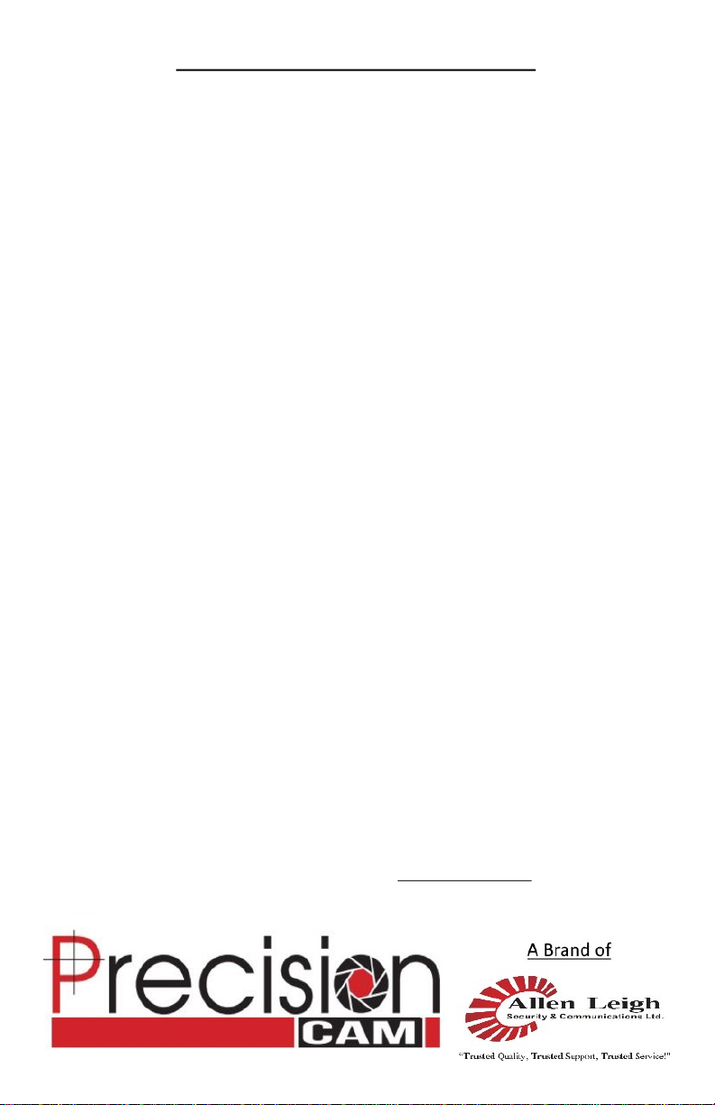
A) PTZ Camera,
B) camera mount with mounng hardware,
C) transmier with antennas, mounng bracket, and mounng hardware,
D) 30’ Camera power cable (red cable with orange ends),
E) 30’ Transmier power cable (red cable with black ends),
F) camera cable (black cable with round ends),
G) camera power supply with mounng hardware,
H) transmier power supply with mounng hardware,
I) PTZ joysck controller with power supply and antenna (excluded from add-on
kit) your unit may come with a smaller antenna then shown,
J) receiver with power supply, 12’ RCA cable, antenna, and remote (excluded
from add-on kit).
WHAT COMES WITH THE PTZ CAMERA KIT
2
10X Mini 26X Side Mount
26X Top Mount

WHAT COMES WITH THE FIXED CAMERA KIT
A) Fixed camera with mounng hardware,
B) transmier with antennas, mounng bracket, and mounng hardware,
C) 30’ Transmier power cable (red cable with black ends),
D) camera cable (black cable with round ends),
E) transmier power supply with mounng hardware,
F) receiver with power supply, 12’ RCA cable, antenna, and remote (excluded
from add-on kit).
WHAT COMES WITH THE DVR KIT
A) Digital Video Recorder (DVR) with power supply, mouse, and remote,
B) 6’ HDMI cable,
C) Cat5 network cable (standard length is 30’),
D) data box,
E) BNC to RCA adapter (kit comes with one for each receiver being used).
3
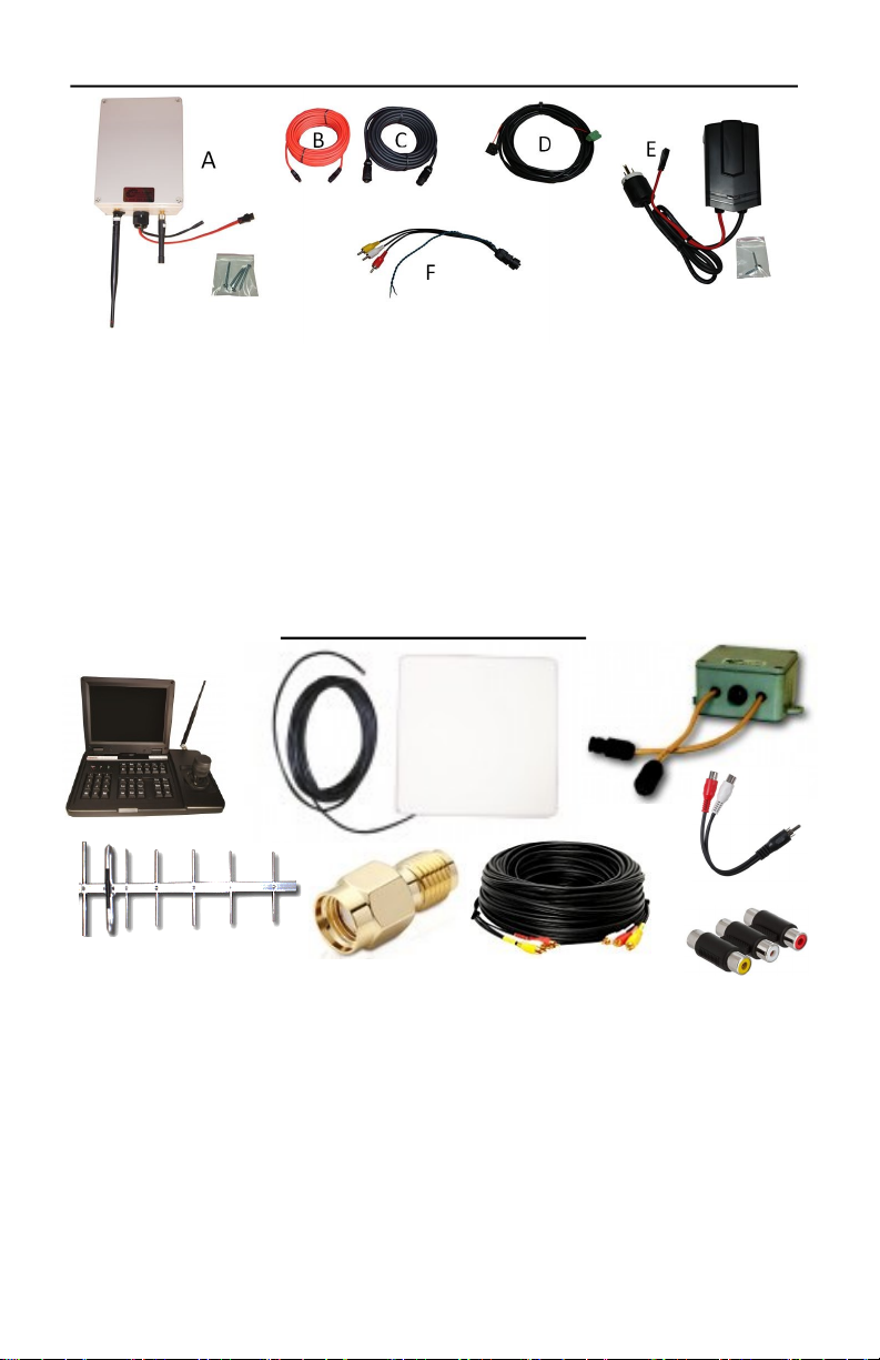
OTHER ACCESSORIES
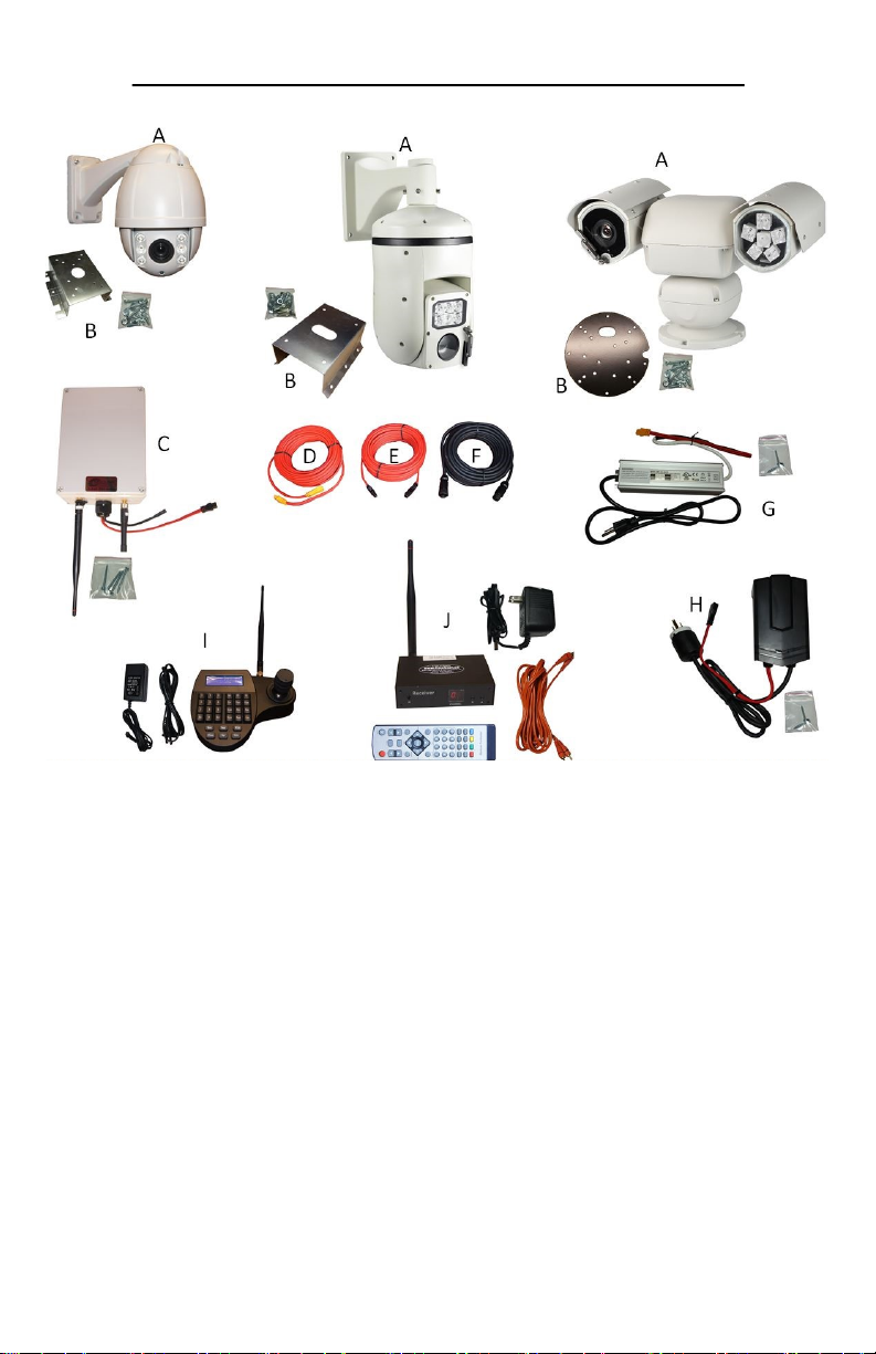
WHAT COMES WITH THE OUTDOOR RECEIVER KIT
A) Outdoor receiver with antennas, mounng bracket, and mounng hardware,
B) 30’ receiver power cable (red cable with black ends),
C) video cable (black cable with round ends),
D) cable to connect controller to outdoor receiver adapter with terminal block
(black cable with red and Black wires inside ) usually about 12’ long,
E) receiver power supply with mounng hardware,
F) outdoor receiver video and data adapter/splier.
A) PTZ joysck controller with built in LCD monitor,
B) high gain panel antenna for transmier or receiver,
C) audio mod,
D) high gain YAGI antenna for PTZ controller or data box,
E) SMA antenna adapter,
F) extra long RCA cable for receiver (comes in 25,50, or 100 foot),
G) RCA splier cable,
H) RCA coupler.
A
BC
DE
FG
H
4
QUICK SETUP GUIDE FOR IN-HOUSE TESTING
We do strongly recommend you watch our DVD manual and fully assemble your
system in your house before proceeding with the nal installaon. This will ensure you
have a full understanding of how the system works, and will also allow you to verify
everything works and nothing was lost or damaged in transit.
Below is a quick reference diagram to aid you in assembling the system to test it in the
house. If you get stuck you can skip forward to the full installaon instrucons for help.
This diagram includes the most common type of setup, there will be full installaon
instrucons later in the manual for all types of equipment.
In house assembly diagram:
5

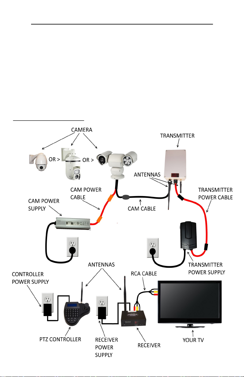
SETTING UP AT THE HOUSE: STANDARD SETUP
If you have a DVR start at the next page
Once you have nished seng up and tesng everything in the house its me to get
things up and running.
We will start at the house. First get your receiver, power supply, antenna, and RCA
cable.
• Twist the antenna marked “for receiver” on to the gold antenna connector on
the back of the receiver unit and point it up.
• Next, connect one end of the RCA video cable to the audio and video out con-
nectors on the back of the receiver. Normally you can match the colors of the
connectors, but if your cable does not have a yellow plug, you will have to use
another one of the connectors in its place such as black.
• Now, connect the other end of the RCA cable to your TVS video input. This is
somemes called video1, AV1, or composite. Some TVS do not have a dedicated
yellow video plug , in this case you will need to use the green connector.
• Connect the power supply to the power input on the back of the receiver unit
and plug it in to a wall power connecon.
• Place the receiver on a high surface with the antenna poinng up, facing the
wall that faces the barn or camera locaon.
(see page 33 for more ps on best receiver placement)
Now we will setup your controller. You will need the PTZ joysck controller, power
supply, and antenna.
• Twist the antenna marked “for controller” onto the antenna connector on the
back of the controller, and point the antenna up.
• Next, connect the power supply to the power in port on the back of the control-
ler and plug it in to a wall power connecon.
• Place the controller on a stable surface where it will not be exposed to high
levels of stac electricity.
• Standard setup diagram:
6

7
SETTING UP AT THE HOUSE: DVR SETUP
(SMART PHONE OPTION)
The DVR or Digital Video Recorder (AKA the smart phone opon) allows you record
with your CowCam, and also connects your cameras to the internet so you can view
them remotely from a cellphone or tablet.
To set up your DVR you will need your DVR, power supply, HDMI cable, Data box, cat5
network cable and mouse.
• Connect the HDMI cable to the HDMI port on the back of the DVR, then con-
nect the other end of the cable to one of your TV's HDMI inputs (make note of
what input you use).
• Next, connect one end of the cat5 network cable to the LAN port on the back of
the DVR, connect the other end of the cable to and unused LAN port on your
internet router.
• Connect the USB cable of the data box to the USB port on the back of the DVR
(USB cable is for power only), and connect the red and black wires to the A/B
ports on the back of the DVR red=A black=B.
• Connect the mouse to the USB port on the front of the DVR.
• Connect the power supply to the power input jack on the back of the DVR and
plug it into a wall connecon.
Next we will get the receiver or receivers connected to the DVR. You will need your
receivers, power supplies, RCA cables, antennas, and BNC to RCA adapters.
• Twist the antenna marked “for receiver” on to the gold antenna connector on
the back of the receiver unit and point it up.
• Next, connect one end of the RCA cable to the audio and video out connectors
on the back of the receiver. Normally you can match the colors of the connect-
ors, but if your cable does not have a yellow plug, you will have to use another
one of the connectors in its place such as black.
• Now, connect the other end of the RCA cable to the input of the DVR using the
BNC to RCA adapters. In most cases audio is unused for DVR applicaons so
you can leave the red and white audio cables disconnected. If you have more
than one receiver, connect them all to the DVR in order from CH 1 to CH4 only
connecng the yellow video cables.
• Connect the power supply to the power input on the back of the receiver unit
and plug it in to a wall power connecon.
• Place the receiver on a high surface with the antenna poinng up and facing
the wall that faces the barn or camera locaon.
(see page 33 for more ps on best receiver placement)
SETTING UP AT THE HOUSE: DVR SETUP
(SMART PHONE OPTION)
8
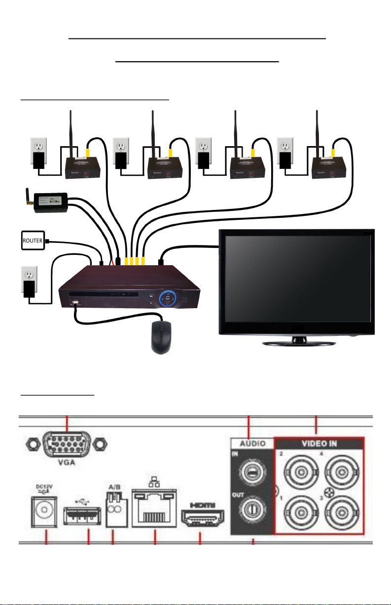
Rear view of DVR:
(To see how to set up the DVR to work on your smartphone go to page 30)
DVR setup diagram with 4 receivers:

If you require an outdoor receiver there are some special set up instrucons:
• The outdoor receiver kit allows you to move the receiver to the outside of the
house to achieve a beer line of sight and baer signal.
• The outdoor receiver also contains a data transmier for your PTZ controller to
allow for a beer line of sight for the control signal as well.
• The outdoor receiver must be mounted outside your house facing toward your
barn or camera locaon.
• You will need to have a power connecon within 30’ of the receiver mounng
locaon.
• We don't recommend mounng it directly below the eaves trough or roof line
as this will expose the receiver to more water and ice which may hinder its
performance.
To set up your outdoor receiver you will need the outdoor receiver, receiver power
supply, video cable, receiver power cable, outdoor receiver adapter, PTZ joysck
controller, controller cable, controller power supply, mounng bracket, and mounng
hardware.
• First, line up the mounng bracket where you want to mount the receiver.
Mark and drill 4 holes, then secure the bracket with the included mounng
screws.
SETTING UP AT THE HOUSE: OUTDOOR RECEIVER
SETUP
• Next, screw the antennas onto the antenna connectors on the boom of the
transmier, paying aenon to the labels on the antennas and receiver to
make sure they are in the correct posion.
9

SETTING UP AT THE HOUSE: OUTDOOR RECEIVER
SETUP
• Now, using the included nuts, bolts, and washers, aach the receiver to the
mounng bracket, making sure the antennas and connectors are facing down.
• Connect the video cable to the matching port on the boom of the outdoor
receiver.
• Run the video cable into the house to your TV locaon from where you wish to
view the camera.
• Connect the receiver power cable to the matching connector on the outdoor
receiver, and run the cable towards the power connecon.
• Mount the receiver power supply near the power outlet using the supplied
mounng screws and connect the transmier power cable to it. Do not plug in
the power supply yet.
10

SETTING UP AT THE HOUSE: OUTDOOR RECEIVER
SETUP
• Connect the outdoor receiver adapter to the camera cable and plug the RCA
cables to your TVs video input. This is somemes called video1, AV1, or
composite. Some TVs do not have a dedicated yellow video plug, in this case
you will need to use the green connector (see next secon for instrucons for
use with DVR).
• Now, connect the controller cable to outdoor receiver adapter using the
supplied terminal block . Red wire to green wire, black wire to blue wire.
• Connect the other end of the controller cable to the back of the joysck
controller using the green 5 pin terminal block that came with the controller.
Red wire goes to A+, black wire goes to B-.
• Next, connect the power supply to the power in port on the back of the control-
ler and plug it in to a wall power connecon.
• Place the controller on a stable surface where it will not be exposed to high
levels of stac electricity.
• Now plug in the receiver power supply.
Outdoor receiver setup diagram:
11
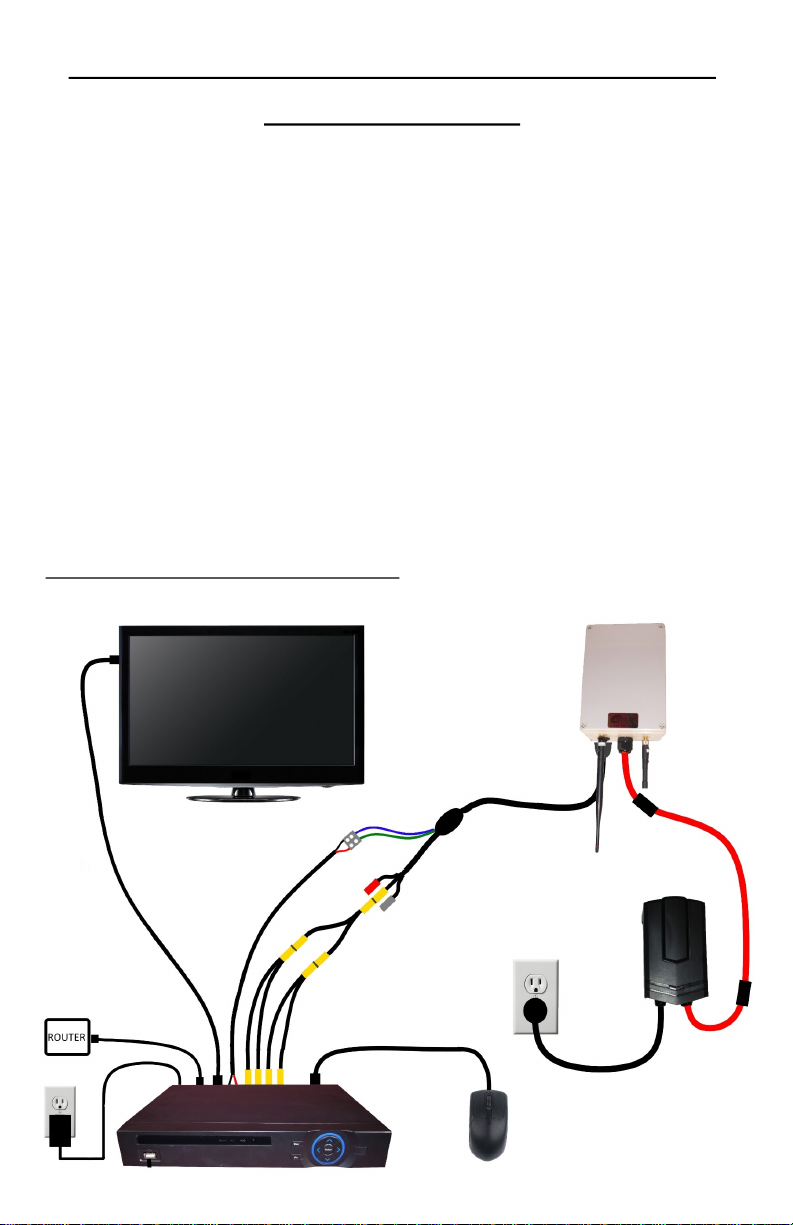
SETTING UP AT THE HOUSE: OUTDOOR RECEIVER
SETUP WITH A DVR
Seng up an outdoor receiver to be used with a DVR is the same as seng it up to be
used with a TV and joysck controller, except instead of connecng the RCA cables to
the TV, you will connect them to the video input of the DVR, and instead of connecng
the controller cable to the PTZ joysck controller, you will connect it to the A/B ports
on the DVR.
• You will not need to use a data box for this type of setup.
• When connecng the controller cable to the back of the DVR, the red wire goes
to the A port, and the black wire goes to the B port.
• If you are using the outdoor receiver with more than one camera, you will need
to use RCA spliers to feed the video signal into all the video inputs of the DVR.
• Please see the DVR setup secon for detail instrucons on seng up your DVR
(pages 28-30).
Outdoor receiver with DVR setup diagram:
12

SETTING UP AT THE HOUSE: LCD CONTROLLER SETUP
To set up the PTZ joysck controller with built in LCD monitor, you will need the LCD
controller, controller power supply, controller antenna, receiver, RCA cable, receiver
power supply, receiver antenna, and BNC to RCA adapter.
• Twist the antenna marked “for controller” onto the antenna connector on the
back of the controller, and point the antenna up.
• Next, connect the power supply to the power in port on the back of the
controller and plug it in to a wall power connecon.
• Place the controller on a stable surface where it will not be exposed to high
levels of stac electricity.
• Twist the antenna marked “for receiver” on to the gold antenna connector on
the back of the receiver unit and point it up.
• Next, connect one end of the RCA video cable to the audio and video out
connectors on the back of the receiver. Normally you can match the colors of
the connectors, but if your cable does not have a yellow plug, you will have to
use another one of the connectors in its place such as black.
• Now, connect the other end of the RCA cable to the controllers video input
connector using the BNC to RCA adapter. Please note the LCD controller does
not support audio, so you will not need to connect the red or white audio
cables to it.
• Connect the power supply to the power input on the back of the receiver unit
and plug it in to a wall power outlet.
• Place the receiver on a high surface with the antenna facing the wall that faces
the barn or camera locaon (see page 33 for more ps on receiver placement).
LCD controller setup diagram:
13
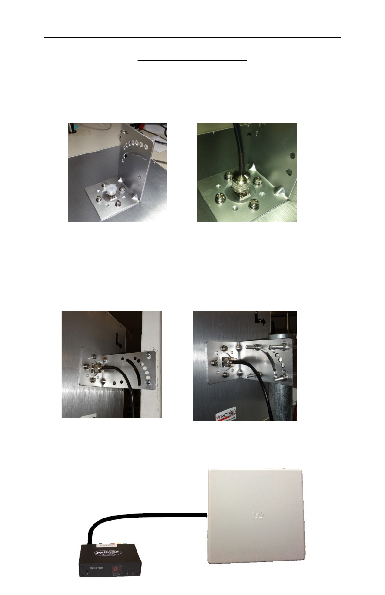
SETTING UP AT THE HOUSE: HIGH GAIN PANEL
ANTENNA SETUP
To set up the high gain panel antenna you will need the panel antenna, mounng
bracket, antenna cable, and mounng hardware.
• Start by aaching the mounng bracket to the back of the panel antenna using
the supplied mounng hardware, and connect the antenna cable.
• Now, mount the antenna with the curved side facing toward the transmier at
the barn. You can mount it using 2 standard wood screws, or with the supplied
pole mounng kit. Pay aenon to the direcon of the H and V arrows to en-
sure the correct orientaon of the antenna. The V arrow should point up, and
the H arrow should point to the right. You may need tweak the orientaon of
the antenna to get the best signal.
• Then run the antenna cable into your house and connect it to the antenna
connector on the back of your receiver. If you already have an antenna on the
receiver it will need to be removed before connecng the cable (max recom-
mended cable length is 20’).
14
SETTING UP AT THE BARN: MOUNTING THE CAMERA
The rst step to seng up at the barn is mounng the camera. You will need your
camera, camera power supply, camera power cable, camera cable, mounng hard-
ware, and your mount. If you have a xed camera, you will not need the mount,
camera power cable, or camera power supply.
• It is ok to mount the camera outside as it is completely weather proof, however
we don't recommend mounng it directly below the eaves trough or roof line
as this will expose the camera to more water and ice which may hinder its
performance.
• You will need to have a power connecon within 30 feet of the camera
mounng locaon. If you have a xed you do not have to worry about this as
the camera is powered through the camera cable.
• Before starng the installaon, make sure you will be able secure the camera
mount directly to a stud or into a solid pole. If this is not possible, we
recommend reinforcing with 3/4” plywood or beer.
Your mounng kit includes: 1 camera mount, 4 track bolts, 4 washers, 4 lock nuts, and
4 lag bolts.
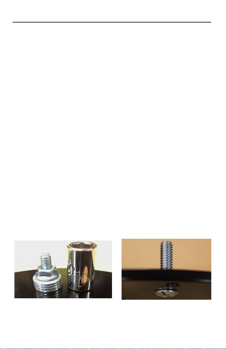
• The rst thing you need to do is set the 4 track bolts in the mount to create
studs for the camera. To do this, put the bolt through the correct hole, then on
the opposite side, stack up the 4 washers on the bolt with the nut on top, then
ghten the nut unl the track bolt pulls itself into the hole. You can also use a
hammer to set the bolts in place if you wish.
• To determine what holes to put the track bolts in, put the camera over the
mount and observe which holes line up with the mounng plate of the camera.
• Now, place the mount where you wish to install the camera, mark out and drill
the 4 mounng holes with the appropriate sized drill bit, and fasten the mount
with the 4 included lag bolts.
15
Table of contents
Other Precision CAM Measuring Instrument manuals


