VEGA
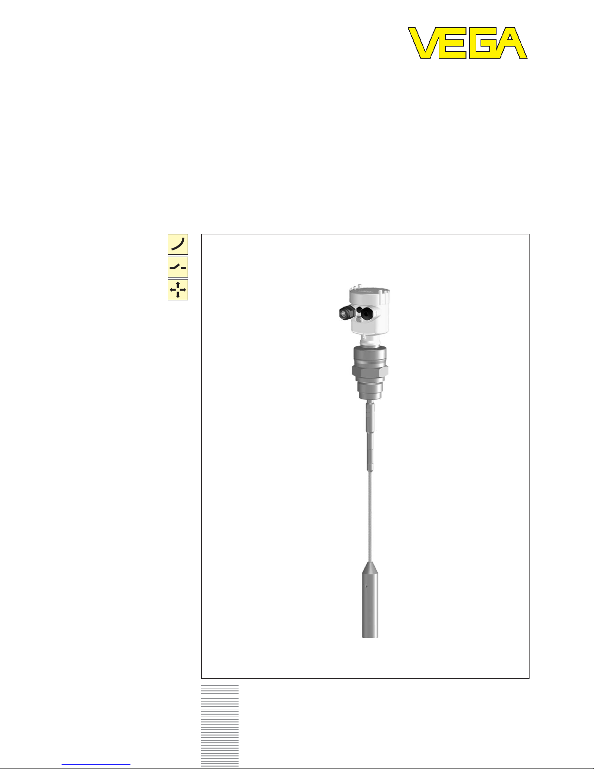
FLEX 62 – 4 … 20 mA/HART®
5
2
7822-EN-030715
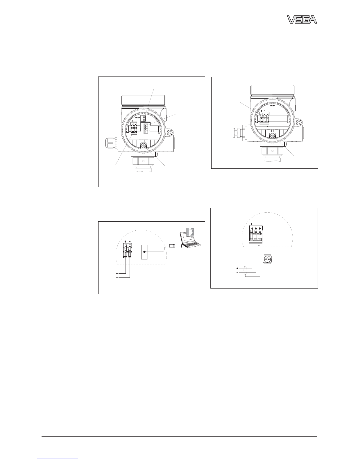
Connection to power supply
2 Connection to power supply
2.1 Preparing the connection
Take note of safety instructions for Ex
applications
In hazardous areas you should take
note of the appropriate regulations and
type approval certificates of the sen-
sors and power supply units. The sen-
sors must only be operated on intrinsically safe
circuits. The permissible electrical values are
stated in the certificate.
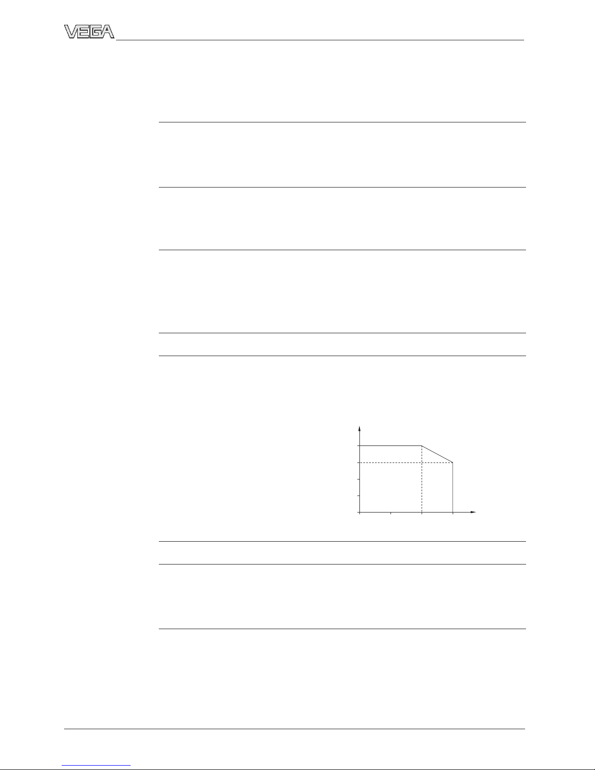
Select voltage supply
VEGAFLEX requires a supply voltage of
14 … 36 V DC. Power supply and current signal
are led via the same two-wire connection cable.
Provide a reliable separation between the exter-
nal energy source and the mains circuits acc. to
DIN VDE 0106 part 101. The VEGA power supply
units VEGATRENN 149AEx, VEGASTAB 690,
VEGADIS 371 as well as all VEGAMETs meet this
requirement. When using one of these instru-
ments, protection class II is ensured for
VEGAFLEX 62.
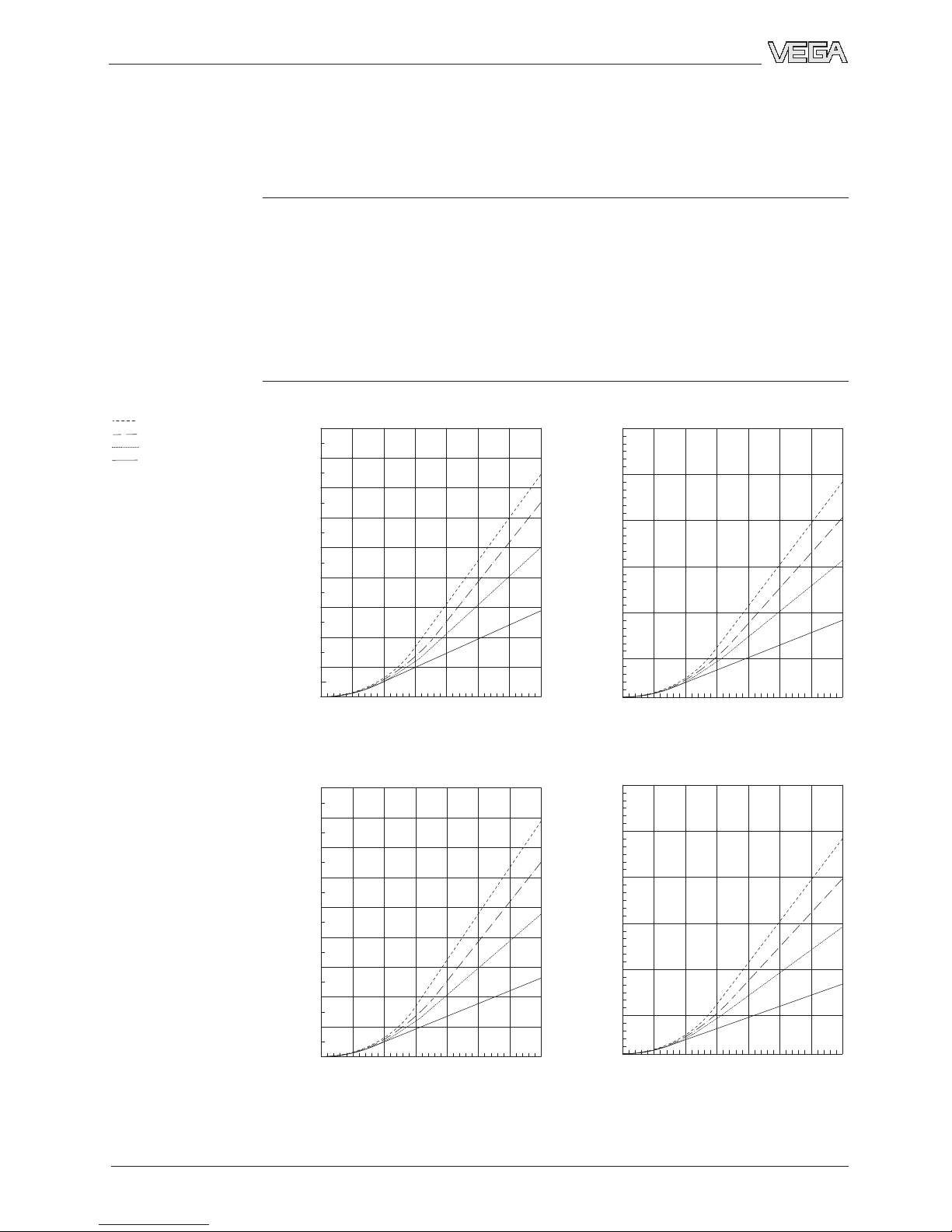
Bear in mind the following factors regarding
supply voltage:
• Reduction of the output voltage of the power
supply unit under nominal load
• Influence of additional instruments in the cir-
cuit (see load values in Technical data).
Anschlusskabel auswählenSelect connec-
tion cable
VEGAFLEX is connected with standard two-wire
cable. An outer diameter of 5 … 9 mm ensures
the seal effect of the cable entry.
If strong electromagnetic interference is ex-
pected, shielded cable is recommended. The
screen should be applied on both ends.
Select connection cable for Ex
applications
Take note of the corresponding installa-
tion regulations for Ex applications.