Precision CAM Cow Cam User manual


1
Table of Contents
Introduction ……………………………………………………………………..……… 1
Table of Contents .……………………………………………………………. …………1
Warranty ………………………………………………………………………...……… 2
New Customers ………………………………………………………………....……… 2
Basic Kits ……………………………………………………………………..………... 3
General Information ..………………….………………………………….. …………... 4
Transmitter Information ……………………………………………….…….…………. 4
Setup Instructions ……………………………………………………………….……... 5
Indoor Equipment ……………………………………………………….……….. 5
Outdoor Equipment ……………………………………………………..……….. 5
Small PTZ Camera Mounting ……………………………………………………......... 6
Large PTZ Camera Mounting ……………………………………………………......... 7
Top Mount PTZ Camera Mounting
Programming /Camera Operation …………………………………………..……......... 8
Creating Preset Location Points ………………………………………………..... 8
Tour ……………………………………………………………………...……..... 9
Quick Presets …………………………………………………………………… 10
Troubleshooting …………………………………………………………….……......... 10
Additional Equipment
DVR …………………………………………………………………………….. 11
Audio Mod ……………………………………………………………...……… 13
Expansion Pack ………………………………………………………………… 14
High Gain Antenna ……………………………………………………..………. 14
Thank you for purchasing your PTZ-IR Livestock Monitoring System (Cow Cam) from
us. You will get many years of use from your new wireless video system, it comes with
a one-year warranty on parts and labor, and we guarantee it to work when installed
according to our assessment.
If you have any problems please contact our office at
1 (204) 728-8878 1-866-289-8164
Thank You! And Enjoy!
Like us on Facebook /AllenLeighSC
Follow us on Twitter @AllenLeighSC
Also check out additional accessories on
www.allenleigh.ca

2
Attention:
New Customers
Please ensure that you set up your complete Camera System in house
first before final outside installation.
This will enable our Technicians to accurately assist you, should you
have any problems. You can also visit www.cowcam.cathen click support
on the left hand side for after hours troubleshooting steps
If you are within Manitoba or Saskatchewan please do not forget to send one copy of your
invoice back to us with your section/township/range and signature for Cow Cam to be PST exempt!
WARRANTY COVERAGE:
Allen Leigh Security is proud to offer one year warranty on our livestock monitoring systems
which covers parts and manufacturer defects. The warranty does not include the following;
キActs of nature (this includes tornado, hail, voltage surges caused by lightning or improper
wiring and flooding damage etc.)
キImproper use or installation of CowCam systems causing damage or improper
functionality of camera or equipment
キAbuse or mechanical damage resulting in system failure. Such as dropping or hitting
equipment
キFull submersion in liquids of any sorts accidental or otherwise.
キUser error resulting in equipment damage or failure.
If there is a requirement to return your system to ALSC, please contact us to receive an
RMA#, write your RMA# on the package being shipped, and ensure that it is shipped properly
with adequate packaging to protect it in transport, ALSC covers shipping one way.
Please note that in any case warranty is needed ALSC wants to ensure that we can provide
you with a replacement or loaner as soon as possible so you continue to use your camera
system. In order for ALSC to offer this service we will charge your credit card, once ALSC has
received the faulty equipment and it has been verified we will fully refund the deposit charge
on the card provided. In the care of a loaner equipment, you will be charged a deposit which
will be credited back to your card upon return of the loaner equipment.
3
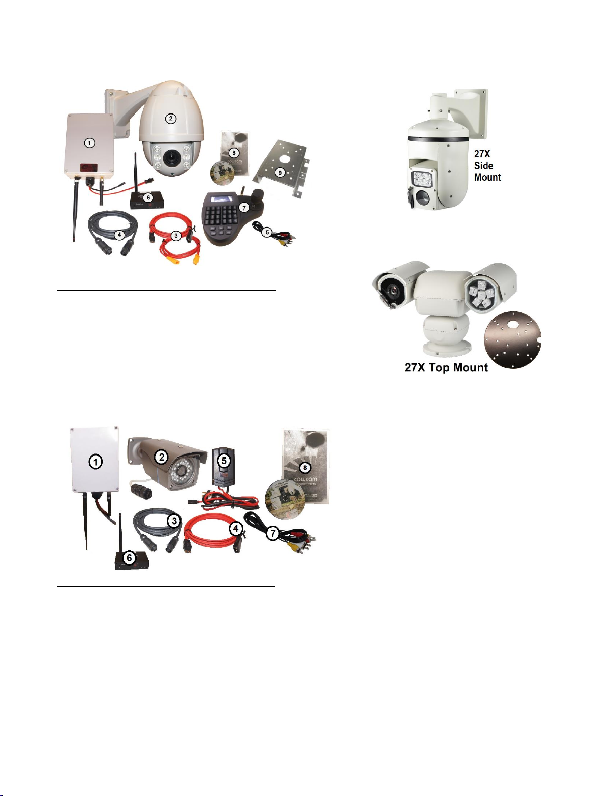
Your Complete PTZ CowCam Kit comes with:
1. 1 - Transmitter Box
2. 1 - PTZ Camera (Large/ Mini) - 10X PTZ shown above
3. 2 -30 ft. Power Cables (red with black & Orange ends)
4. 1 - 6 pin 30 ft. PTZ Camera Cable (Black)
5. 1 –15’ RCA Cable
6. 1 - Wireless Receiver
7. 1 - Camera Controller
8. PTZ-IR Cam Manual and PTZ Installation DVD
9. Camera mounting bracket (and hardware)
Camera and transmitter power supplies
Your Complete Fixed Camera Kit comes with:
1. Transmitter Box
2. Color Camera with stand and IR LED lights
3. 30ft of camera cable
4. 30 ft. Power Cable (red with black ends)
5. Transmitter power supply
6. Receiver with a power supply & remote
7. RCA cable (red, yellow, white ends)
8. Instruction manual

4
General Information
The system consists of two main parts, a barn side, and a house side.
On the end where the camera will be located (the barn) is also where the transmitter box and power supply will
be mounted (on the outside of the building facing the house where the receiver will be located) The transmitter
and camera will be connected together with the camera cable. A power supply will also be connected to the
camera. The receiver will be located at the viewing location (your house) and connected to your TV with the
RCA cables. The joystick controller will also be located at the house
.
The camera and transmitter will be provided with a power supply and color coded 10 meter cable
We strongly recommend using a surge protector and grounding the camera mount to prevent potential damage
in the case of power surges or lightning.
Basic Setup Instructions:
*NOTE: Please see the Optional Equipment section for setup and information on any additional
equipment you have purchased.*
Indoor Equipment (House Side)
Begin by plugging the power supply for the receiver into the back of the receiver (DC 12V). Plug the
Yellow RCA cable into (video) the back of the receiver and the other end will plug into your T.V or DVR (into
the yellow video jack). (The standard channel select setting for the receiver is #1). You only need to connect the
audio RCA cables (white/red) if you purchased the optional Audio modification box.
Screw the mini bud antennae to the back of the PTZ controller, finger tight. Connect the power supply to the
PTZ camera controller. This will be the only connection to the controller that is required—the unit operates
wirelessly.
Please note that the controller is not connected to video it controls camera
movement only.
The signal to operate the movement of the camera will be sent wirelessly via the
antenna on the PTZ controller.
Outdoor Equipment (Barn Side)
Now that you have the receiver and controller set up, we will now set up the outdoor equipment. Starting
with the camera, plug the camera cable into the 6-pin male connecter end on the camera. The other end of the
camera cable will be connected to the bottom of the transmitter where there is a 6-pin female connector that it
will plug into.
Each of the power cables will get plugged into their associated power supply. Making sure that the color
coordinated cables are matched Plug in the power supply box to a 110V outlet and the camera will begin is
startup routine. During which time it will display on the TV screen its information such as its address, baud rate,
and protocol.
Once you plug in the controller, make sure that the controller and camera are on the same address, take

5
note of what the address of the camera is from the TV s when it does its startup routine, and then enter in that
address number on the keypad of the PTZ Controller followed by the CAM button. (Eg Dome ID: 001, on the
keypad of the controller press: 01 on the PTZ controller then CAM button. That will set the address on the
keypad to 01 and you will be able to control the camera with address 01.) Normally the camera and controller
addresses will be 01 (001), but that is not always so.
Transmitter Information
If you unscrew the 4 Phillips screws on the front of the transmitter you will be
able to take the cover off. Please do not over tighten them as they will break. Be sure
to replace the lid in the correct orientation or it will not seal correctly. Tip: note the
position of the logo before removing the lid.
Inside of the transmitter box you will find a LED display this will tell you what
channel this particular transmitter is on, it can be switched to one of seven frequencies.
You can change the channels by using the two buttons. If you push the channel selector
once, it will go to channel two, once more to three etc. go to channel 3, and so forth.
Be sure not to have more than one transmitter set on the same channel, i.e.
channel one (you won’t damage anything but the video picture at the house will look
very scrambled). Ensure that the channel you have the transmitter set on matches the
channel on the receiver at the house.
There is no on/off switch for the transmitter or camera; the only way to turn it off is to unplug the unit.
We strongly recommend that you unplug the unit after your calving season is complete, and wrap up the
plug end, as damage may occur during thunderstorms and extremely high winds due to power lines clashing.
You will know that the unit is powered on when the channel indicator is lit inside the transmitter box.
There is a mounting bracket that is sent with the
unit so you can mount it to a pole or wall. The
transmitter must be mounted outside. Install it
so it fits tightly to the mounting location.
Connect camera to mount. Connect power
cables to power boxes. Finally run the camera
cable from the transmitter to the camera.
Caution: ensure the cable does not get cut by
any sharp edges from the hole you cut. Also be
sure to aim the transmitter so that it points
towards where the receiver is located. The
transmitter should be mounted in the vertical
position with the mounting hardware on the
bottom, the transmitter sticker facing the
receiver location and the antennas pointed down.

6
Camera Mounting Instructions
Small PTZ
Kit Includes:
(1) LMS-MNT-PTZ-SM universal mount bracket
(4) 1‖ X 1/4‖ track bolts for camera attachment
(4) 1/4‖ lock washer nuts
(1) 5/16‖ flat washer (for setting track bolts)
Step #1: Installing track bolts
Choose the camera mount bolt pattern before installing
track bolts.
If a bolt pattern is not available drill 17/64‖ holes for other patterns.
Install the track bolt from the inside of the mount and use the four 5/16 flat washer (between the
nut and mount base) to help the bolt into the 17/64‖ hole
Use a wrench to tighten the nut thus pulling the track bolt into firm position.
The track bolts can also be hammered into place
Step #2: The MNT-PTZ-SM-001 mount bracket
Can be used for the following applications:
* Flat Mounting
*Corner Mounting
*Pole Mounting
*Flat mounting example:
Installing #14 or 1/4‖ self taping hex head screws after track bolts
installed (plywood is only used for demonstration purposes, not needed for
installation. Use six screws for a solid mounting into wall.) - See image to the left
*Corner Mounting example:
Bending of mounting flanges in a vise to the appropriate angle is required (#14 or 1/4‖
diameter attachment screws required) - See images to the right
Pole mounting example:
Flanges bent to appropriate angle for pole diameter (use a Stainless
large size hose clamps or self taping screws #14 or 1/4‖) - See below
Step #3:
After the LMS-MNT-PTZ-SM mount bracket is fixed to the wall or
pole, the camera can be attached to it using 1/4‖ nuts (supplied). The wiring can led through the
hole or outside as necessary.
Example: (flat mount shown)
Step #4: Next take the power cable from the power supply box with orange end and plug
it into the matching plug on the camera. An optional extension cable may be supplied.
The cable with the black end from the power supply box will get plugged into the matching plug on the
transmitter.

7
Large PTZ
The large camera mount LMS -MNT-PTZ-LRG can be used to mount the camera on a telephone pole or exterior corner of
a building.
It is made of stainless steel and supplied with 3/8‖ course thread track bolts and flange nuts.
The track bolts must be installed in the mount so that they project out toward the camera mount.
To install the track bolts, use the 4 washers provided as a spacer, then pull the track bolt into the mount with the supplied
3/8‖ course flanged nuts. The track bolts may also be hammered in.
**mount the bracket on the pole or wall before installing the camera**
Two methods of attachment to a pole are available:
Step #1: use 4 or 6, 3/8‖ lag screws –see left image
Step #2: 4 or 6, large stainless adjustable tie straps –see right
image
Exterior Corner Mounting:
The camera mount bracket is designed to fit on a corner of a building.
Use 2‖X3/8‖ lag screws to solidly mount it on an exterior corner.
Flat Wall Mounting:
Large 3/8‖ hex self-taping lag screws are available for fastening
the mount directly to a wall. It is recommended that if the camera
is being mounted directly to a wall, that 1‖ plywood backing plate
be solidly attached to the wall, then the camera attached to the
plywood backing using 3/8‖ X 2‖ lag screws.
Step #3: Next take the power cable from the power supply
box with orange end and plug it into the matching plug on
the camera. An optional extension cable may be supplied.
The cable with the black end from the power supply box
will get plugged into the matching plug on the transmitter.
Top Mount Installation
Kit Includes:
(1) LMS-MNT-PTZ-TM (Mounting Plate)
(2) 1‖x1/4‖ track bolts X4 (for mounting the plate)
(3) ¼‖ lock washer nuts X4
(4) 5/16‖ washers
Mounting Plate: Hardware:

8
Instructions include the following:
How to pull track bolts into the mounting plate.
How to fasten the mounting plate to top of pole.
How to fasten camera to the mounting plate.
Step #1 –Setting Track Bolts:
Step #2 –Fastening Mounting Plate to Pole:
-Typically the mounting plate would be fastened to the top of a light post (telephone pole). In this
case a 4x4 Post was just used as an example.
-If using a wooden pole - Pre-drill 1/8” holes for lag bolts
-Paint can also be removed from bottom of plate, and welded in the case of a metal pole.
-Locate four holes in a square pattern
you will be using to mount the camera.
-Put your track bolt through one of the 4 holes.
-Put all 4 washers over the end of the bolt and thread on a
nut.
-Using an 11mm Socket or wrench. Firmly tighten the nut
to pull the bolt into a properly set position.
-A hammer can also be used to set the track bolt.

9
-When fastening the mounting plate to a proper
pole, much more holes can be utilized for added
strength.
-If mounting surface is big enough, outside holes can
also be used.
Step #3 –Fastening Camera to Mounting Plate:
-To ensure camera cable does not get pinched, and make the running of the cables easier, first feed
connectors through the oval shaped hole in the plate (Only if Mounting surface allows an opening
underneath!)
Lastly put camera on the mounting plate with bolts coming through the mounting holes on camera.
-Add lock nuts. And tighten down firmly.

10
Programming / Camera Operations
Moving Camera
To move the camera you push the joystick left to move to left and right to move the camera to the right.
The harder you push the joystick, the faster the camera moves; a slight push moves the camera slowly.
You can also use the joystick for zooming out by turning the knob clockwise and zoom in by turning the
knob counter clockwise.
Controller Buttons
The top rows of 12 buttons are accessory buttons that will not be used for the
application you will be using the controller for.
The 6 buttons on right hand side closest to the joystick
are your manual camera functions i.e. Wide = zoom in, tele=zoom out, open & close will be
how you open & close the menu, near & far are your focusing buttons.
You can change the ID of the camera by pressing the prev & next buttons i.e. If your on
camera ID 01 it will change it to camera ID 02, so if your camera ID is 01 and the controller
is on camera ID 2 then it will not control your camera. Please remember for cases you don’t
have control.
Note that, when using the screen controller, the image on the screen will not change automatically when the ID
is changed. To change the camera being viewed, first change the ID on the controller and then move the joystick
in any direction.
These are the main buttons that you will use on the controller.
- Press 95 &Pre to enter the menu of the camera.
-To display the menu of the controller to ensure that everything
matches the camera (baudrate, protocol & camera ID), press and
hold shi & set, do the same to remove this menu. This should
only be done to verify the controller settings match the camera
settings in the event you are having trouble controlling the
camera.
How to make an Auto Scan
For 27X Side Mount and Top Mount
1. Move your camera to the furthest left position that you want the camera to scan to
2. On controller keyboard press ―SET‖ and then ―1‖ then the ―SCAN‖ button (your left limiter is now set)
3. Move the joystick to position the camera to the furthest right location you want to scan to
4. On controller keyboard press ―SET‖ and then ―2‖ then the ―SCAN‖ button (your right limiter is now set)
5. To view the Auto Scan that you set press ―1‖ and then ―SCAN‖ button to the start scan
Note: to change the speed of the scan, see the keyboard controlling section in the keyboard manual
For 10X
1On the Keyboard PTZ Controller, press ―95‖ ―PRE‖ to get into the PTZ cameras on-screen display
2When you see the on-screen display on your TV, use the joystick (push down) to scroll down to #2 Dome,
then press the ―NEAR‖ button to enter (NEAR button is on the left 3 from the top)
3On the next screen use the joystick to go down to #3 A–B SCAN, and press the ―NEAR‖ button to enter
4Select which preset points (see below)
11
To Stop the Auto Scan, just move the joystick, to restart use the appropriate speed number and CALL button
again
Creating Preset Location Points
1. Position your camera on the point of interest that you want to view, you can zoom in/out on the object
location.
2. Once you have your location determined, on the Controller keypad press ―PRESET‖ then the location
number you want to create (such as 1, 2,3, etc) and ―PRESET‖ button again
3. Continue the above step for each separate location you want to create (giving it its own number preset 1-
90)
4. There is room to create up to 90 locations ranging from #1 to #90
5. To check your preset locations press the preset number on the keypad (for that location) and then PRESET
button. An example sequence would be ―3‖ ―PRE‖ which would move the camera to the preset location
you made called #3.
To Create a Tour of your Preset Locations
When you have all of your preset location made you can use this next step to view them automatically in
whatever order you want in a continuous order.
For 27X Side Mount and Top Mount
1. On the Keyboard PTZ Controller, press ―95‖ ―PRE‖ to get into the PTZ cameras on-screen display
2. When you see the on-screen display on your TV, use the joystick (push down) to scroll down to #3 Auto-
Run, then press the ―NEAR‖ button to enter (NEAR button is on the left 3 from the top)
3. On the next screen use the joystick to go down to #3 TOUR, and press the ―NEAR‖ button to enter
4. On the next screen use the joystick to go down to #2 SETUP, and press the ―NEAR‖ button to enter
5. You will now be in the setup screen to setup up the Tours.
For 10X
6. On the Keyboard PTZ Controller, press ―95‖ ―PRE‖ to get into the PTZ cameras on-screen display
7. When you see the on-screen display on your TV, use the joystick (push down) to scroll down to DOME,
then press the ―NEAR‖ button to enter (NEAR button is on the left 3 from the top)
8. On the next screen use the joystick to go down to GUARD TOURS, and press the ―NEAR‖ button to enter
9. On the next screen use the joystick to go down to SETTING, and press the ―NEAR‖ button to enter
10. You will now be in the setup screen to setup up the Tours.
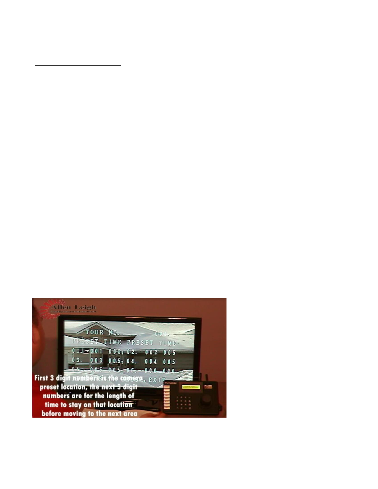
If you see this information displayed you
have made the correct option choices. The
numbers may look a bit confusing,
hopefully the following explanation helps.
Where you see 01. 001 005
1. 01. represents the start of the Tour
(there are 12 tour locations)
2. 001 represents the camera pre-set
location
3. 005 is the length of time to stay on
that pre-set point in seconds
Use the joystick to move the arrow to the
number that you want to change, when
you are on the number you want to change use the ―NEAR‖ and ―FAR‖ buttons to increase or decrease the
number.
12
You can set the tour to start with any one of your pre-set locations, and have it stay on for the length of time you
want in seconds. You can have up to 12 tour locations set if you like.
Once you have the tour set to your liking, press the ―OPEN‖ button (also known as Iris +) to save and then Press
―CLOSE‖ button to exit.
To View your tour on the Controller keyboard press tour number (ex. “1”) and then “TOUR”
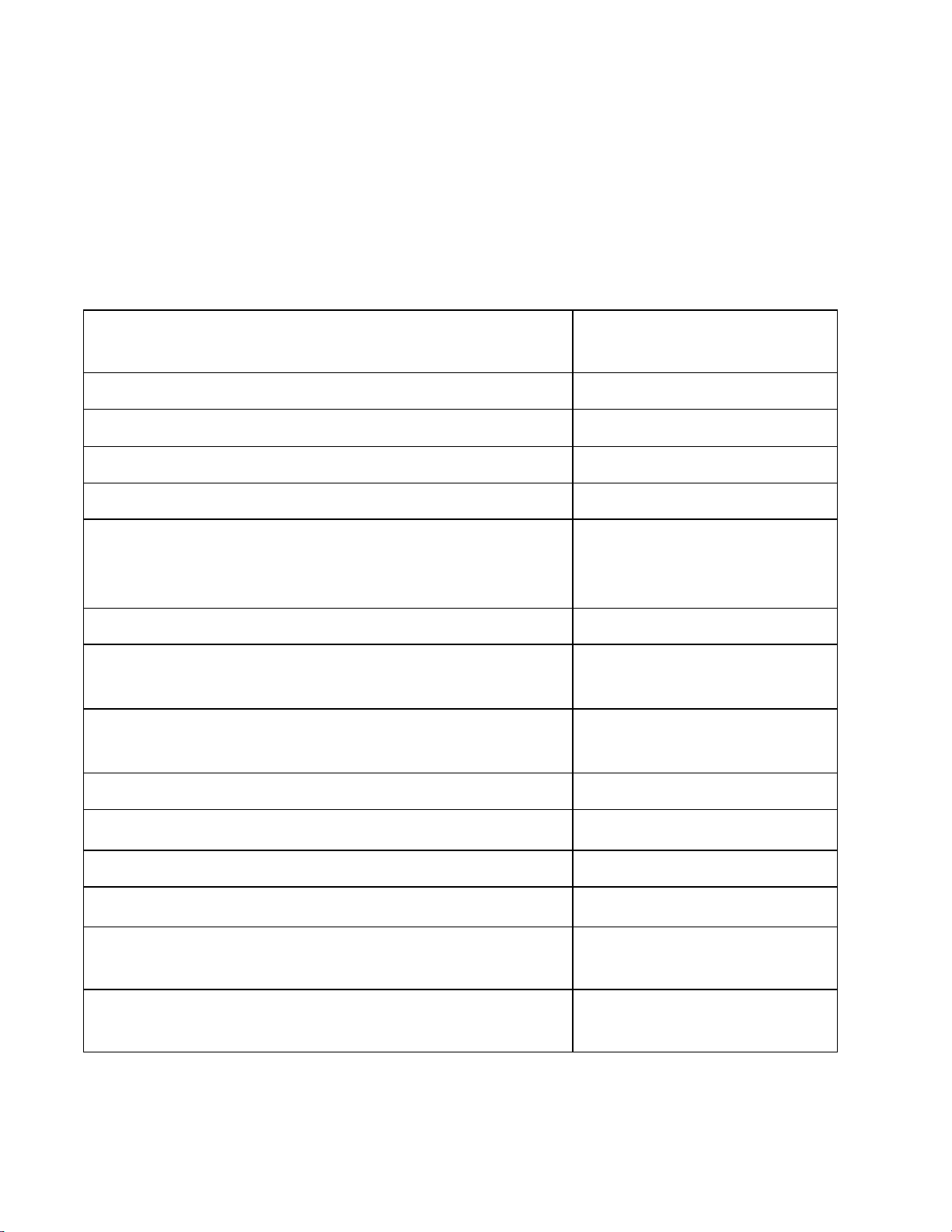
Quick Guide
Joystick
Move camera
- turn knob to zoom
9 + 5 + PRE
Open camera menu
SET
Open and close controller menu
SET + # + PRESET
Set up Preset location
# + PRESET
Call Preset location
“9+5+PRESET” - “Function Settings” - “Tour” - “Edit Tour”
OR
“9+5+PRESET” - “Dome” - “Guard Tours” - “Setting”
Set up Tour
# + TOUR
Call Tour
SET + # + PAT (start)
SET + 0 + PAT (end)
Set up Pattern
“9+5+PRESET” - “Function Settings” - “Patterns” - “Program
Pattern” - “Run Pattern”
Call Pattern
6 +3 + PRESET
Activate camera wiper
PREV & NEXT
Change camera ID on controller
WIDE & TELE
Zoom in and zoom out
NEAR & FAR
Focus camera
“9+5+PRESET” - “Camera Settings” - “Advanced Settings 1” -
“IR Cut Filter” and Change it to “Auto/Colour/(Black/White)
Turn on/off IR LED’s
6 + 2 + Preset
SET + 6 + 2 + PRESET
Turn on/off IR LED’s (If IR’s are
set to manual)

13
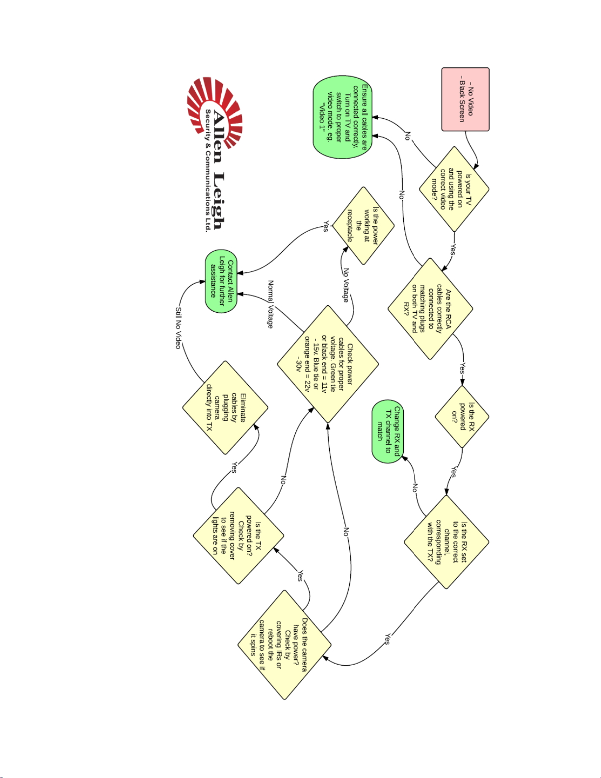
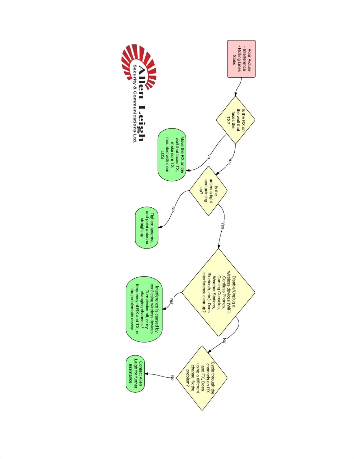
Picture Problems
If you do not get a picture right away, upon completing your connection you may have to unplug and
plug the transmitter back in, this does a system reset, and usually rectifies the problem if there is no picture
from the system.
If you have any problems please refer to our website for a step by step troubleshooting chart www.cowcam.ca
this will take you directly to the support page:
If you have tried these steps and still unable to fix the problem please give us a call to speak to our helpdesk;
**Please note for the basic system it is very important that the receiver be located on the same side of the
house as the transmitter is located (you may try other locations once you have acquired your signal)
preferably on the inside of the outside wall so the two units can see one another through only one wall with
as little obstruction as possible.
Trees, shrubs and hay bales do not seem to hinder the picture quality too much during the
winter, trees do effect the signal once the leaves come out. You may find that you may have to adjust
the antenna or the receiver unit by lifting it up for better reception.
If you have buildings or machinery in the way, it will possibly lower your picture quality, it also
depends on what the buildings are made of, metal or large machinery block the signal. It is best not to
have anything in the way of the signal path, we understand that you cannot move buildings so try to
position the transmitter higher up above the roofline or higher than the objects in the way.
If you are placing the receiver in front of a window and you are not getting a good picture it
could be due to the type of windows. High energy efficiency windows in particular may restrict or
block the signal. These windows contain Argon gas or a coating that seems to block the signal, just
move the receiver over from the window and you will more than likely get a signal.
Metal siding will not allow a strong signal into the home if the receiver is placed behind it, so
you will want to try to place the receiver near a window location. You may have to re-position the
antenna angle on the receiver in order to find the best signal with the basic models you may find that
you have to move the receiver up or down, trial and error will get you the best signal.
Stucco, foil covered foam, cement board, and brick may also disrupt or block the signal.
If you continue to have problems receiving a signal we do have optional external antennaes that
are available as well as outdoor receivers.
If you have any problems please refer to our website for a step by step troubleshooting
chart www.cowcam.ca this will take you directly to the support page:
If you have tried these steps and still unable to fix the problem please give us a call to
speak to our helpdesk;
Office: 204-728-8878 Or Toll Free: 1-866-289-8164
Thank You and Enjoy!
Allen Leigh Security & Communications Team
14
15

16

17
DVR Installation Instructions:
Step 1: Unpack everything from the DVR box. You should have:
(1) DVR
(1) Remote
(1) Mouse
(1) Power supply
(1) HDMI cable
(*) RCA to BNC connectors 1 per receiver
(1) Data Box
Step 2: connect the RCA to BNC connectors to the back of the DVR.
Step 3: plug the mouse into the USB port on the front of the DVR
Step 4: plug one end of the HDMI cable into the HDMI port on the
back of the DVR. Plug the other end into your TV
Step 5: Plug the cable on the Data Box into the USB port on the back of
the DVR.
Step 6: Plug the two bare wires on the
Data Box adapter into the green slots on
the back of the DVR. Use a screwdriver
to depress the red tabs and allow you to
plug in or remove wires.
A = Red wire B = Black wire
Step 7: plug the power supply into the wall and into the back of the
DVR.
Step 8: plug one end of the RCA cable provided with your receiver into the back of the receiver and the
other end into the corresponding port on the back of your DVR. (ie. CH 1, CH 2, CH 3, CH 4)
You should be able to view your cameras and DVR screen on your TV
Getting your cameras on your smart phone
Peer to Peer(P2P)
Step 1: enable DHCP:
A) Log into your DVR:
User name: user
Password:8878
B) go to Settings>Network>choose tcp/ip
C) for mode click the DHCP box and hit apply then save .
Step 2: enable P2P
A) From the main menu go to Settings>Network choose P2P on the left. Click the enable box and hit the Save button at
the bottom
B) go to Settings>Network to the P2P menu and click online. Then Save.

18
Step 3: get your Serial Number and QR scan Code
A) From the main menu go to Info>System
B) On the left hand side go to Version. This will show your scan code and Serial Number. Keep this screen up for the
next part.
If you have an Iphone download an app called IDMSS LITE then open the app.
1push the lines ichon in the upper left. This is your menu push the device manager menu option to open.
2Push the + ichon on upper right for a new connection.
3Choose P2P
4Hit the QR Scan at the top
5Take a picture of the QR Scan Code on your Monitor
6Give the connection a name
7Enter your user name and password for the DVR
8Click Live preview at the bottom to see your cameras
If you have an Android phone.. Download an App called GDMSS LITE and launch it
1Click the Play button in the upper right
2Click the plus button to make a new connection
3Click the QR Scan Code
4Take a picture of the QR Scan Code on your monitor
5Enter a name for the connection
6Enter your user name and password for the DVR
7Click Live Preview at the bottom to see your cameras
Port Forwarding:
Port forwarding requires a bit more knowledge of your router in order to set up for you. For assistance with port
forwarding please call technical support.
Office: 204-728-8878
or
Toll Free: 1-866-289-8164
Port Forwarding:
What is port forwarding?
port forwarding or port mapping is an application that redirects a communication request from one address and port
number combination to another while the packets are traversing a network gateway, such as a router or firewall This
technique is most commonly used to make services on a host residing on a protected (internal) network available to hosts
on the opposite side of the gateway (external network), by remapping the destination IP address and port number of the
communication to an internal host.
Why is it important?
We use port forwarding to remove any barriers that may block your camera signals going up through the internet and down
to your phone or tablet. Your Internet Service Provider (ISP) may also block ports on their end and prevent you from
getting the signal through. The ports we use are 37777, 5554 and 8080. It is important that these ports be opened by your
ISP or you will be unable to have your smart phone connect to your cameras outside your local network..
19
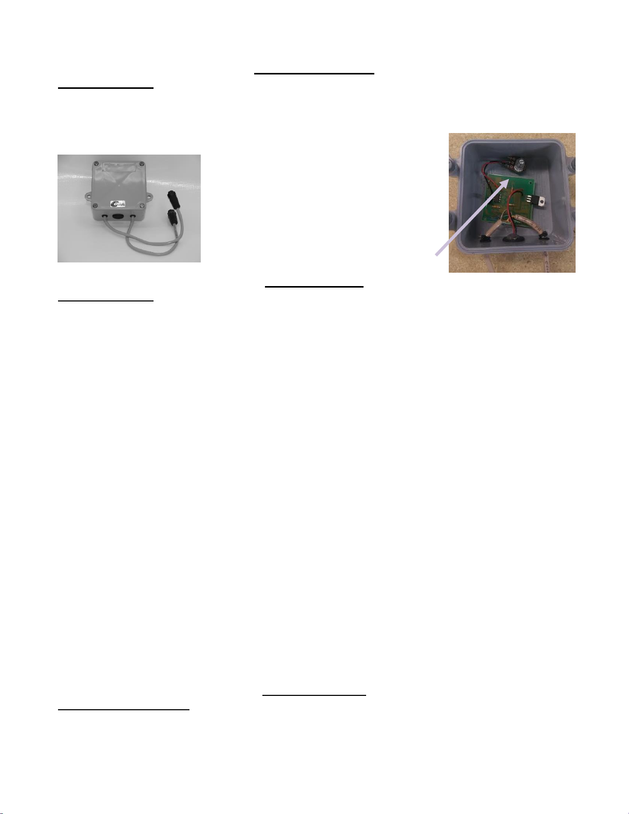
Audio
Box
Audio Modification
Installation Steps:
If the Audio Modification Box option was purchased, you will have two cable ends, they are
setup so that the camera end will fit into one side and the camera cable into the other the connectors,
the connectors on the audio box are opposites. The audio modification box is
designed to be mounted onto the wall it has
mounting holes for it. You can mount the
audio mod either right before the camera or
the transmitter box which ever works best for
you. On the inside of the Audio device you
will see an adjustment knob, this is how you
would adjust your audio sensitivity.
Expansion Pack
Installation Steps:
You will notice that the cameras are labelled ID1, ID2, ID3, & ID4.
This is to match the ports on the expansion box (white) Cam1, Cam2, Cam3 & Cam4. Please plug the
camera into the corresponding plug, this is to ensure movement of your camera.
You will plug the receiver using the stereo plugs or RCA cords that have come with your system into
the video port of your TV. All the camera's video signal will be coming in on one channel (usually CH
1). The way you would switch back and forth from camera1 to camera2 and so forth will be though
your PTZ controller.
If you would like to see the camera that is plugged into Cam Port1 you will press 1 CAM on the
controller then move the joystick. If it’s the camera that is plugged into Cam Port2 then you will press
2 CAM on the controller then move the joystick and so on.
If you have purchased a DVR with your Expansion Pack you will have special adaptors that will plug
into all 4 channel ports on the DVR. (You will see the same camera on all 4 channels) In order to
switch from camera to camera, whether it be on the DVR itself or through the app on your phone, you
will right click and click on View1 then you will select the camera in the drop down box that you wish
to view. This will switch to that camera on that port of the expansion box. You will then need to right
click again and click on pan tilt/ zoom once the little screen pops up you can press on any of the arrows
to send a signal and that video on that port will open up. You will need to continue these steps for every
other camera you wish to view.
**Please note that the Expansion pack was not originally designed to work with a DVR. This is a new
development that we have made to help make your calving easier, safer and more profitable. Some
extra steps are required to use it in this way.
High Gain Antenna
Installation Instructions:
If you purchased the optional external High Gain Antenna to get better distance, you will want to use
the same guide lines as for the standard antenna. You will need to remove the rubber spike antenna and
This manual suits for next models
1
Table of contents
Other Precision CAM Measuring Instrument manuals

Popular Measuring Instrument manuals by other brands


FujiFilm
FujiFilm FUJI DRI-CHEM IMMUNO AU CARTRIDGE vf-SAA Instructions for use

Endress+Hauser
Endress+Hauser Proline Promass E 300 operating instructions

FuturePlus Systems
FuturePlus Systems FS2010 user manual

Agilent Technologies
Agilent Technologies 100 user guide

Zico
Zico ZI-9100 Operating instruction

Endress+Hauser
Endress+Hauser Soliwave FQR56 operating instructions