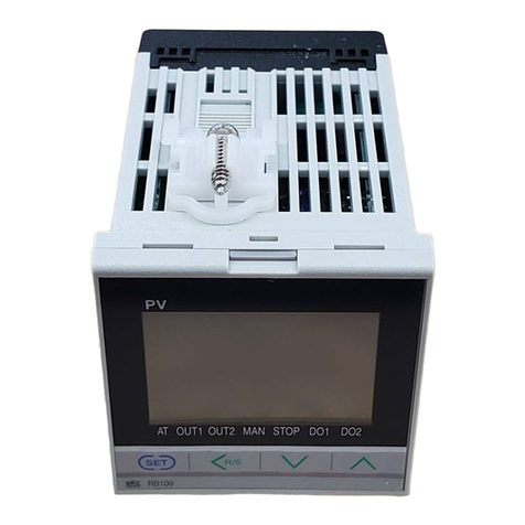
Precision Digital Corporation SuperNova PD500 User manual

SuperNova PD500 PID Process & Temperature Controllers
Instruction Manual
PRECISION DIGITAL CORPORATION
233 South Street • Hopkinton MA 01748 USA
Tel (800) 343-1001 • Fax (508) 655-8990
www.predig.com
•1/16, 1/8, and 1/4 DIN Auto-Tuning PID Process & Temperature Controllers
•Thermocouple and RTD Inputs
•DC Voltage and Current Inputs (1-5 V, 0-5 V, 0-10 V, 0-50 mV, 0-100 mV; 4-20 mA with Resistor)
•250 Ω Resistor(s) Included Standard
•High Accuracy Auto-Tuning PID
•High Durability Front with Hard Plastic Pushbuttons
•Large Easy to Read 14-Segment PV Display up to 1.1" (29 mm)
•Input Power 100-240 VAC
•Heating, Cooling, and Heating & Cooling Control
•Primary Control Output Options: 4-20 mA (SCR), Voltage Pulse (SSR), or Relay
•Secondary Control Output Relay Standard on All Models
•Easily Switch Between Auto and Manual Control Modes
•Up to 2 Alarm Relays & 4-20 mA Retransmit Outputs
•Remote Set Value 1-5 V Input Option (4-20 mA with External Resistor)
•Digital Input Set Value Selection
•RS-485 Serial Communications Option
•Modbus® RTU/ASCII Communications
•Mini-USB Port Standard
•FREE Programming and Monitoring Software
•1/16, 1/8, 1/4 DIN Sizes Available
•Shallow Depth Case Extends Only 2.5" (63 mm) Behind Panel
•IP65 Fronts
•UL & C-UL Recognized Process Control Equipment, Electrical - Component

SuperNova PD500 PID Process & Temperature Controllers Instruction Manual
2
Disclaimer
The information contained in this document is
subject to change without notice. Precision Digital
makes no representations or warranties with
respect to the contents hereof and specifically
disclaims any implied warranties of
merchantability or fitness for a particular purpose.
See Warranty Information and Terms &
Conditions on www.predig.com for complete
details.
•Read complete instructions prior to installation
and operation of the controller.
•Risk of electric shock or personal injury.
•This product is not recommended for life support
applications or applications where malfunctioning
could result in personal injury or property loss.
Anyone using this product for such applications
does so at his/her own risk. Precision Digital
Corporation shall not be held liable for damages
resulting from such improper use.
WARNING
Cancer and Reproductive Harm - www.P65Warnings.ca.gov
Operation & Care Notes
Limited Warranty
Precision Digital Corporation warrants this
product against defects in material or
workmanship for the specified period under
“Specifications” from the date of shipment from
the factory. Precision Digital’s liability under this
limited warranty shall not exceed the purchase
value, repair, or replacement of the defective unit.
See Warranty Information and Terms &
Conditions on www.predig.com for complete
details.
Registered Trademarks
All trademarks mentioned in this document are
the property of their respective owners.
© 2021 Precision Digital Corporation.
All rights reserved.

SuperNova PD500 PID Process & Temperature Controllers Instruction Manual
3
Table of Contents
Introduction......................................................................................................... 6
Abbreviations ................................................................................................. 6
General Controller Term Descriptions.......................................................... 6
Range and Scale Descriptions..................................................................... 6
Engineering Unit Descriptions...................................................................... 7
Ordering Information.......................................................................................... 8
Enclosures...................................................................................................... 9
Accessories .................................................................................................... 9
Specifications ................................................................................................... 10
General.......................................................................................................... 10
Process Input ............................................................................................... 10
Temperature Input........................................................................................ 11
Control Outputs............................................................................................ 11
Alarm Relay Outputs.................................................................................... 12
4-20 mA Retransmit Output......................................................................... 12
Remote SV Process Input............................................................................ 12
USB Connection........................................................................................... 12
Digital Inputs ................................................................................................ 12
Modbus® RTU Serial Communications...................................................... 13
SuperNova TCS Software ............................................................................ 13
Compliance Information................................................................................... 14
Safety ............................................................................................................ 14
Electromagnetic Compatibility.................................................................... 14
Safety Information ............................................................................................ 14
Operation & Care Notes............................................................................... 15
Installation......................................................................................................... 15
Unpacking..................................................................................................... 15
Panel Mounting Instructions ....................................................................... 16
Controller Dimensions................................................................................ 17
Connections ................................................................................................. 18
Connectors Labeling .................................................................................. 18
Power Connections.................................................................................... 19
Signal Connections .................................................................................... 19
Relay Connections..................................................................................... 19
4-20 mA Output Connections..................................................................... 20
Digital Input Connections ........................................................................... 20
Remote SV Input Connections................................................................... 20
Modbus RTU Serial Communications ........................................................ 20
Digital Input Connections ........................................................................... 20
Controller Operation ........................................................................................ 21
Change Control Set Value (SP) ................................................................. 21
RUN/STOP Modes..................................................................................... 21
Menu Timeout ............................................................................................ 21
Front Panel ................................................................................................ 21
Front Panel Buttons and Status Indicators................................................ 22
Setup and Programming.................................................................................. 23
Overview ....................................................................................................... 23
Setting Up the Controller............................................................................. 23
Programming the Controller ....................................................................... 24
Set Value Group (G.SV) ............................................................................ 24
G.SV Parameter Details............................................................................. 24
Input Group (G.IN) ..................................................................................... 25
G.IN Parameter Details.............................................................................. 26
Output Group (G.OUT) .............................................................................. 27
Output Limit High (OL-H) and Low (OL-L).................................................. 28
G.OUT Parameter Details.......................................................................... 29
Settings Group (G.SET)............................................................................. 30
Power-On Operation Mode (POOM).......................................................... 30
G.SET Parameter Details........................................................................... 31
Communication Group (G.COM)................................................................ 32

SuperNova PD500 PID Process & Temperature Controllers Instruction Manual
4
G.COM Parameter Details ......................................................................... 33
Sub Relay Group (G.SUB)......................................................................... 34
G.SUB Parameter Details .......................................................................... 36
Transmit & Remote Group (G.TRS)........................................................... 37
G.TRS Parameter Details .......................................................................... 38
Alarm Group (G.ALM) ................................................................................ 39
G.ALM Parameter Details .......................................................................... 43
Control Group (G.CTL) .............................................................................. 44
G.CTL Parameter Details........................................................................... 47
SuperNova TCS Software ................................................................................ 49
Remote Programming.................................................................................. 49
Data Acquisition........................................................................................... 49
Monitoring..................................................................................................... 49
Monitoring with RS-485 Connection........................................................... 49
SuperNova TCS Installation ........................................................................ 49
Running SuperNova TCS the First Time......................................................... 50
SuperNova TCS Main menu ........................................................................ 50
Top Level Menus .......................................................................................... 50
Troubleshooting Tips....................................................................................... 52
Error Messages ............................................................................................ 53
Modbus Register Tables .................................................................................. 54
Fixed Modbus Tables................................................................................... 54
General Process and Indication, Address 0 - 99........................................ 54
Set Value Group (G.SV), Address 100 - 199 ............................................. 54
Control Group (G.CTL), Address 200 - 299 ............................................... 55
Alarm Group (G.ALM) Address, 300 - 399................................................. 56
Transmit Group (G.TRS), Address 400 - 499............................................. 56
SUB Relay Group (G.SUB), Address 500 - 599......................................... 57
Communication Group (G.COM), Address 600 - 699 ................................ 57
Set Value Group (G.SET), Address 700 - 799 ........................................... 57
Output Group (G.OUT), Address 800 - 899) .............................................. 58
Input Group (G.IN), Address 900 - 999 ...................................................... 58
User Defined Modbus Map .......................................................................... 58
Modbus Register Bit Information................................................................ 59
Register Bit Assignment............................................................................. 59
Bit Definitions............................................................................................. 59
EU Declaration of Conformity.......................................................................... 61

SuperNova PD500 PID Process & Temperature Controllers Instruction Manual
5
Table of Figures
Figure 1. Panel Cutout Dimensions ................................................................ 16
Figure 2. PD510 Mounting Bracket Installation.............................................. 16
Figure 3. PD520 and PD530 Mounting Bracket Installation .......................... 16
Figure 4. Controller Dimensions ..................................................................... 17
Figure 5. Recommended Terminal Connectors ............................................. 18
Figure 6. PD510 Connector Diagram .............................................................. 18
Figure 7. PD520 & PD530 Connector Diagram............................................... 18
Figure 8. PD510 Power Connection ................................................................ 19
Figure 9. PD520 & PD530 Power Connection................................................. 19
Figure 10. PD510 Signal Connection .............................................................. 19
Figure 11. PD520 & PD530 Signal Connection............................................... 19
Figure 12. PD510 Relay Connections ............................................................. 19
Figure 13. PD520 & PD530 Relay Connections.............................................. 19
Figure 14. PD510 4-20 mA Retransmit Connections ..................................... 20
Figure 15. PD520 & 530 4-20 mA Retransmit Connections........................... 20
Figure 16. PD510 Digital Input Connections .................................................. 20
Figure 17. PD520 & PD530 Digital Input Connections................................... 20
Figure 18. PD510 Remote SV Input Connections .......................................... 20
Figure 19. PD520 & PD530 Remote SV Input Connections........................... 20
Figure 20. PD510 RS-485 Connection............................................................. 20
Figure 21. PD520 & PD530 RS-485 Connection ............................................. 20
Figure 22. Front Panel Buttons and Indicators .............................................. 22
Figure 23. Input Type and Range Selection ................................................... 25
Figure 24. Heating & Cooling Hysteresis........................................................ 28
Figure 25. Alarm Operation when ON & OFF Time delays are Set............... 34
Figure 26. Alarm Type and Number Table...................................................... 39
Figure 27. Alarm Operation Description Table............................................... 40
Figure 28. High Absolute Alarm Operation .................................................... 41
Figure 29. High Absolute Alarm Operation without Standby........................ 41
Figure 30. High Absolute Alarm Operation with Standby ............................. 41
Figure 31. High Absolute Alarm with Latch Function ................................... 41
Figure 32. Loop Break Alarm (LBA) Operation in Reverse Action Mode..... 42
Figure 33. Standard and Low PV Auto-Tuning SV......................................... 45
Figure 34. Response Adjustment with Alpha................................................. 46
Figure 35. Set Value Ramp Up......................................................................... 46
Figure 36. Set Value Ramp Down.................................................................... 46

SuperNova PD500 PID Process & Temperature Controllers Instruction Manual
6
Introduction
The SuperNova PD500 Series of PID Process & Temperature Controllers is a complete line of PID and on/off
controllers. Available in popular 1/4, 1/8, and 1/16 DIN sizes, and with a shallow depth behind panel of only 2.5"
(63 mm) it is easy to fit into almost any panel, product, or enclosure.
Voltage, current (with external resistor), and direct temperature thermocouple and RTD inputs make it an excellent
choice for any control application requiring easy to change, visible set points.
This modern line of controllers shows the process variable (PV), set value (SV), and manipulated value (output
level%, MV) on a striking reverse polarity LCD screen. Indicators for units (˚C, ˚F,%, or none)
Auto and manual control modes can be easily changed by holding two buttons, and this is indicated on the front panel
to make it easy for operators to know how to use this feature.
Main control outputs can be 4-20 mA (SCR), voltage pulse (SSR), or relay outputs. A secondary relay control output
is standard, which allow for one or two direction SV control (i.e., heating and cooling).
Additional outputs may include two SPST alarm relays and a 4-20 mA retransmit output. Other options include a
secondary 4-20 mA input to remotely control the set point, and RS-485 for Modbus communication.
A mini-USB port may be used for a direct PC connection to run the SuperNova software for monitoring, programming,
and data logging. This USB port is located on the rear behind the panel for PD510 1/16 DIN models, and on the front
behind a rubber tab on PD520 and PD530 1/8 and 1/4 DIN models.
Abbreviations
The following abbreviations are used throughout this manual.
General Controller Term Descriptions
Abbreviation Full Meaning
PV Process value
SV Set value
MV Manipulated value (Output value %)
AT Auto-tuning
REM Remote set value
RET Retransmission 4-20 mA output
SUB1 SUB1 output (alarm relay 1)
SUB2 SUB2 output (alarm relay 2)
LBA Loop break alarm
EU Engineering unit
EUS Engineering unit, total span
Range and Scale Descriptions
FR.L Full Range Low: The temperature range is defined according to the thermocouple or RTD type selected.
The minimum temperature value of this range is referred to as the FR.L (full range, low).
Example: For a type K thermocouple, the FR.L is -200 °C.
FR.H Full Range High: The temperature range is defined according to the thermocouple or RTD type
selected. The maximum temperature value of this range is referred to as the FR.H (full range, high).
Example: For a type K thermocouple, the FR.H is 1370 °C.
SL.L Scale Limit Low: The scale range is used when the input is a process signal, voltage or current (with an
external sense resistor). The minimum scale value of the process input is referred to as the SL.L. This
value may be changed with the SL-L parameter to scale the process input to the desired engineering
unit.
Example: For a 1 to 5 VDC input, the default SL.L is -1999. To represent an input value of 0 to 100%,
the SL-L parameter would be changed to 0, making the SL.L 0.
SL.H Scale Limit High: The scale range is used when the input is a process signal, a voltage or current (with
an external sense resistor). The maximum scale value of the process input is referred to as the SL.H.
This value may be changed with the SL-H parameter to scale the process input to the desired
engineering unit.
Example: For a 1 to 5 VDC input, the default SL.H is 9999. To represent an input value of 0 to 100%,
the SL-H parameter would be changed to 100, making the SL.H 100.

SuperNova PD500 PID Process & Temperature Controllers Instruction Manual
7
Engineering Unit Descriptions
During the programming of the controller, there are two types of engineering units referred to, EU, and EUS.
EU: The value in engineering units according to the input range.
EUS: The value in engineering units according to the full span of the input.
Engineering Units (EU)
A parameter or other value defined in EU is defined in the actual absolute engineering unit value of the input type (or
scaled engineering units for the case of voltage or current inputs).
This means the EU value takes on the actual engineering unit value, which may be negative in some cases.
In the example below, the controller has been programmed for a type J thermocouple. A type J thermocouple has a
range of -200°C (FR.L) to 1200°C (FR.H). Any parameter or value using EU unit definitions could be defined in values
from -200°C to 1200°C.
If the parameter or value is defined in EU, but listed as a percentage (EU %), 0% represents the value of -200°C and
100% represents a value of 1200°C.
Engineering Unit Span (EUS)
A parameter or other value defined in EUS is defined in the actual engineering units of the input type (or scaled
engineering units for the case of voltage or current inputs) but represents the span value in those engineering units.
This means the EUS value is defined in engineering units, but begins at 0, representing the low range of input (FR.L
or SL.L) and will not be a negative value, regardless of the actual input range.
In the example below, the controller has been programmed for a type J thermocouple. A type J thermocouple has a
range of -200°C (FR.L) to 1200°C (FR.H), but a span of 1400°C. Any parameter or value using EUS unit definitions
could be defined in values from 0°C to 1400°C.
If the parameter or value is defined in EUS, but listed as a percentage (EUS %), 0% represents the value of 0°C and
100% represents a value of 1400°C.

SuperNova PD500 PID Process & Temperature Controllers Instruction Manual
8
Ordering Information
Model Number
DIN Size
Main Control Output
Additional Features
PD510-A
1/16
4-20 mA (SCR)
Relay Control Output, 2 Alarm Relays
PD510-A-CD
1/16
4-20 mA (SCR)
Relay Control Output, 2 Alarm Relays, RS-485, 2 Digital Inputs
PD510-A-CTR
1/16
4-20 mA (SCR)
Relay Control Output, 2 Alarm Relays, RS-485, 4-20 mA Retransmit, 4-20 mA SV
Input
PD510-S
1/16
Voltage Pulse (SSR)
Relay Control Output, 2 Alarm Relays
PD510-S-CD
1/16
Voltage Pulse (SSR)
Relay Control Output, 2 Alarm Relays, RS-485, 2 Digital Inputs
PD510-S-CTR
1/16
Voltage Pulse (SSR)
Relay Control Output, 2 Alarm Relays, RS-485, 4-20 mA Retransmit, 4-20 mA SV
Input
PD510-R
1/16
Relay (On/Off)
Relay Control Output, 2 Alarm Relays
PD510-R-CD
1/16
Relay (On/Off)
Relay Control Output, 2 Alarm Relays, RS-485, 2 Digital Inputs
PD510-R-CTR
1/16
Relay (On/Off)
Relay Control Output, 2 Alarm Relays, RS-485, 4-20 mA Retransmit, 4-20 mA SV
Input
PD520-A
1/8 (V)
4-20 mA (SCR)
Relay Control Output, 2 Alarm Relays
PD520-A-CTD
1/8 (V)
4-20 mA (SCR)
Relay Control Output, 2 Alarm Relays, RS-485, 4-20 mA Retransmit, 2 Digital
Inputs
PD520-A-CTDR
1/8 (V)
4-20 mA (SCR)
Relay Control Output, 2 Alarm Relays, RS-485, 4-20 mA Retransmit, 2 Digital
Inputs, 4-20 mA SV Input
PD520-S
1/8 (V)
Voltage Pulse (SSR)
Relay Control Output, 2 Alarm Relays
PD520-S-CTD
1/8 (V)
Voltage Pulse (SSR)
Relay Control Output, 2 Alarm Relays, RS-485, 4-20 mA Retransmit, 2 Digital
Inputs
PD520-S-CTDR
1/8 (V)
Voltage Pulse (SSR)
Relay Control Output, 2 Alarm Relays, RS-485, 4-20 mA Retransmit, 2 Digital
Inputs, 4-20 mA SV Input
PD520-R
1/8 (V)
Relay (On/Off)
Relay Control Output, 2 Alarm Relays
PD520-R-CTD
1/8 (V)
Relay (On/Off)
Relay Control Output, 2 Alarm Relays, RS-485, 4-20 mA Retransmit, 2 Digital
Inputs
PD520-R-CTDR
1/8 (V)
Relay (On/Off)
Relay Control Output, 2 Alarm Relays, RS-485, 4-20 mA Retransmit, 2 Digital
Inputs, 4-20 mA SV Input
PD530-A
1/4
4-20 mA (SCR)
Relay Control Output, 2 Alarm Relays
PD530-A-CTD
1/4
4-20 mA (SCR)
Relay Control Output, 2 Alarm Relays, RS-485, 4-20 mA Retransmit, 2 Digital
Inputs
PD530-A-CTDR
1/4
4-20 mA (SCR)
Relay Control Output, 2 Alarm Relays, RS-485, 4-20 mA Retransmit, 2 Digital
Inputs, 4-20 mA SV Input
PD530-S
1/4
Voltage Pulse (SSR)
Relay Control Outputs, 2 Alarm Relays
PD530-S-CTD
1/4
Voltage Pulse (SSR)
Relay Control Output, 2 Alarm Relays, RS-485, 4-20 mA Retransmit, 2 Digital
Inputs
PD530-S-CTDR
1/4
Voltage Pulse (SSR)
Relay Control Output, 2 Alarm Relays, RS-485, 4-20 mA Retransmit, 2 Digital
Inputs, 4-20 mA SV Input
PD530-R
1/4
Relay (On/Off)
Relay Control Output, 2 Alarm Relays
PD530-R-CTD
1/4
Relay (On/Off)
Relay Control Output, 2 Alarm Relays, RS-485, 4-20 mA Retransmit, 2 Digital
Inputs
PD530-R-CTDR
1/4
Relay (On/Off)
Relay Control Output, 2 Alarm Relays, RS-485, 4-20 mA Retransmit, 2 Digital
Inputs, 4-20 mA SV Input

SuperNova PD500 PID Process & Temperature Controllers Instruction Manual
9
Enclosures
Model/Series
Meters
DIN
Material
PDA2301-V
1
1/8 (V)
Plastic NEMA 4X
PDA2302-V
2
1/8 (V)
Plastic NEMA 4X
PDA2303-V
3
1/8 (V)
Plastic NEMA 4X
PDA2304-V
4
1/8 (V)
Plastic NEMA 4X
PDA2305-V
5
1/8 (V)
Plastic NEMA 4X
PDA2306-V
6
1/8 (V)
Plastic NEMA 4X
PDA2301-4
1
1/4
Plastic NEMA 4X
PDA2301-16
1
1/16
Plastic NEMA 4X
PDA3408 1 1/4
Plastic NEMA 4X
with Clear Cover
PDA2600 1-6 1/8 (V)
Stainless Steel
NEMA 4X
PDA2700 1-6 1/8 (V)
Painted Steel
NEMA 4
Need help selecting the right enclosure?
Go to www.predig.com/esu
Accessories
Model
Description
PDX-RES2
250 Ω0.1% Precision Resistor for
SuperNova 4-20 mA Input
PDA7485-I
RS-232 to RS-485 isolated converter
PDA8485-I
USB to RS-485 isolated converter
PD9501
Multi-function calibrator
PDA-LH
Light / horn accessory
MOD-LH
Light / horn / enclosure modification
PDA-
MINIUSB
USB Cable for SuperNova Series, Type
A Male to Type Mini-B Male
PDX6901
Snubber: 0.01 μF/470 Ω, 250 VAC
Signal Splitter & Conditioner Accessories
Model Description
PD659-1MA-1MA
Signal Isolator with One 4-20 mA
Input and One 4-20 mA Output
PD659-1MA-2MA
Signal Splitter with One 4-20 mA
Input and Two 4-20 mA Outputs
PD659-1V-1MA
Signal Conditioner with One 0-10
VDC Input and One 4-20 mA Output
PD659-1MA-1V
Signal Conditioner with One 4-20
mA Input and One 0-10 VDC Output

SuperNova PD500 PID Process & Temperature Controllers Instruction Manual
10
Specifications
Except where noted all specifications apply to
operation at +25°C.
General
Display Wide viewing angle reverse polarity
LCD; PV: white, SV: green, MV: amber
PD510: PV and SV display
PD520: PV, SV, and MV display
PD530: PV, SV, and MV display
Display Height inches (mm)
PV SV MV
PD510 0.60 (15.2) 0.29 (7.4) N/A
PD520 0.81 (20.5) 0.50 (12.8) 0.37 (9.3)
PD530 1.14 (29.0) 0.59 (15.0) 0.43 (11.0)
PV Display
Update Rate
4/second (250 ms)
Non-Volatile
Memory
Settings stored for a minimum of
10 years.
EEPROM life: 1 million writes
Included
Components
Controller with rubber gasket and
mounting bracket, 250 Ω resistor (1%),
and Quick Start Guide. Additional 250 Ω
resistor (1%) provided for models with
remote setpoint input option.
EEPROM Lock Programmable lock or unlock write
access to the EEPROM. When locked,
setting changes stored in RAM (not
saved on power down).
Power 100 - 240 VAC ±10%, 50 / 60 Hz
8.5 VA max.
Insulation
Resistance
20 MΩ minimum, 500 VDC
Dielectric
Strength
3,000 VAC; 50/60 Hz for 1 minute
across power terminals
Environmental
Operating temperature range:
-10 to 50°C (14 to 122°F)
Storage temperature range:
-25 to 65°C (-40 to 185°F)
Relative humidity:
35 to 85% non-condensing
Front Panel IP65
Depth Behind
Panel
Case extends 2.5 in (63 mm) behind
panel.
Required Fuse
UL Recognized, 250 VAC 0.5 A max,
slow-blow fuse.
Use fuses or circuit breakers compliant
with IEC60947-1 or IEC60947-3
Connections Fixed rear screw terminals and
mini-USB
Mounting 1/4, 1/8, or 1/4 DIN panel cutout
required: panel mounting bracket
assemblies are provided.
Weight PD510: 4.2 oz (120 g)
PD520: 7.1 oz (202 g)
PD530: 10.2 oz (290 g)
Warranty 1 year parts & labor. See Warranty
Information and Terms & Conditions on
www.predig.com for complete details.
Process Input
Process Input
Selection
Voltage or current (with external
resistor)
Process Input 1-5 V (4-20 mA), 0-5 V, 0-10 V,
0-50 mV, 0-100 mV
External 250 Ωresistor required to read
4-20 mA. Recommended accessory
PDX-RES2.
Decimal Point Up to 3 decimals.
Input Sampling 20 samples/sec (50 ms per sample).
For display update rate, see Display
Update Rate
Input Accuracy
Input Type
Prog.
No.
Display
Scale Range
Accuracy
4-20 mA*
30
1-5
-1999 to 9999
±0.2% of FS
± 1 digit
1-5 V
30
1-5
0-5 V
31
5V
0-10 V
32
10V
0-50 mV
33
0.05V
0-100 mV
34
0.1V
*To achieve the highest accuracy with a 4-20 mA input to the
controller, connect a 250 Ω(0.1% or higher precision) resistor across
the input terminals. The 250 Ω(1%) resistor included with the product
is not a precision resistor. For precision resistor, order PDX-RES2.

SuperNova PD500 PID Process & Temperature Controllers Instruction Manual
11
Temperature Input
Temperature
Input Selection
Field programmable for thermocouple
or RTD
Thermocouple
Type
K, J, E, T, R, B, S, L, N, U, W, PLII
RTD Type JPT100, PT100
Cold Junction
Compensation
(RJC)
±1.5°C (-10 to 50°C)
RTD Max Line
Resistance
Three wire RTD with identical line
resistance up to 10 Ω
Input Sampling 20 samples/sec (50 ms per sample).
For display update rate, see Display
Update Rate
Input Accuracy
Input
Type
Prog.
No.
Display
Range
Accuracy
K 1 K0 -328 to 2498°F
-200 to 1370°C
±0.2% of FS
± 1 digit
2
K1
-148 to 932°F
-100.0 to 500.0°C
J 3 J0 -328 to 2192°F
-200 to 1200°C
4
J1
-328 to 1652°F
-199. To 900.0°C
E
5
E1
-328 to 1652°F
-199.9 to 900.0°C
T 6 T1 -328 to 752°F
-199.9 to 400.0°C
R
7
R0
32 to 3092°F
0 to 1700°C
B 8 B0 212 to 3272°F
100 to 1800°C
±0.2% of FS
± 1 digit
100 to 200°C:
±2.0% of FS
± 1 digit
S 9 S0 32 to 3092°F
0 to 1700°C
±0.2% of FS
± 1 digit
L
10
L1
-328 to 1652°F
-199.9 to 900.0°C
N 11 N0 -328 to 2372°F
-200 to 1300°C
U
12
U1
-328 to 752°F
-199.9 to 400.0°C
W
13
W0
32 to 4172°F
0 to 2300°C
PLII 14 PL0 32 to 2372°F
0 to 1300°C
JPt100
20
JPt0
-328 to 932°F
-200 to 500°C
21 JPt1 -328 to 932°F
-199.9 to 500.0°C
Pt100
22
Pt0
-328 to 1184°F
-200 to 640°C
23
Pt1
-328 to 1184°F
-199.9 to 640.0°C
Control Outputs
Control
Outputs
Each controller has a main control output
and a secondary control relay output for
two directions of control. The secondary
control relay output is always used for
On/Off operation.
Main Control
Output
4-20 mA output (SCR), voltage pulse
(SSR), or electromechanical relay (On/Off)
outputs available.
Control Type ON/OFF, PID control
Output
Operation
Programmable for reverse or direct action.
Current SCR
Output
4-20 mA linear current output
Load resistance: 600 Ω maximum
± 0.2% of FS ± 1 digit
Voltage Pulse
SSR Output
12 V ± 1 VDC
Load resistance: 600 Ω minimum
Recommended minimum cycle time: 1 sec
Relay Output Rated resistive load switching capacity:
5 A, 250 VAC; 5 A, 30 VDC
Max switching power: 750 VA, 90 W
Max switching voltage: 250 VAC, 110 VDC
Max switching current: 5 A
Mechanical life: 20 million cycles (at 180
CPM)
Recommended minimum cycle time: 20 sec

SuperNova PD500 PID Process & Temperature Controllers Instruction Manual
12
Alarm Relay Outputs
Function Programmable for 13 different alarm
types or off.
Number Two alarm relays standard on all
models.
Alarm Relay
Ratings
Rated resistive load switching capacity:
5 A, 250 VAC; 5 A, 30 VDC
Deadband 0-100% FS, user selectable
High or Low
Alarm
User may program any alarm for high,
low, or high-low range operation.
Absolute or
Deviation Alarm
User may program any alarm as an
absolute value alarm or a set value
deviation alarm.
Loop Break
Alarm
User may program any SUB alarm relay
as a loop break alarm.
Alarm Relay
Operation
•Automatic (non-latching)
and/or manual reset
•Latching (requires manual
acknowledge) with/without
clear
•Off (disable unused relays)
Relay Reset
(Acknowledge)
Automatic, front panel button, in setup
parameter menu, or through serial
communications
Time Delay
0 to 999 seconds, on and off delays;
programmable for each SUB relay.
Fail-Safe
Operation
Programmable, independent for each
alarm relay. Relay coils are energized in
non-alarm condition. In case of power
failure, relays will go to alarm state.
Standby
Operation
Programming, independent for each
alarm relay
Auto
Initialization
When power is applied to the controller,
relays will reflect the state of the input to
the controller unless standby mode is
enabled.
4-20 mA Retransmit Output
Function
4-20 mA linear current output
Scaling Range 0-100% of full scale
Output Loop
Resistance
600 Ω maximum load
Output Accuracy
±0.2% of full scale ± 1 digit
0-10 VDC Output The PD659-1MA-1V can convert the
optional 4-20 mA output to a 0-10 VDC
output
Remote SV Process Input
Function Process input to remotely change SV
Input Type &
Range
1-5 V, 4-20 mA
External 250 Ωresistor required to read
4-20 mA.
Input Accuracy
±0.2% of full scale ± 1 digit
USB Connection
Function
SuperNova software connection only
Location PD510: Top, behind panel
PD520 & PD530: Front mounted behind
rubber seal, accessible from front panel
Communication
UMS (USB Mass Storage) 2.0
Compatibility USB 2.0 Standard, Compliant
Connector Type Mini-USB receptacle
Cable
USB A Male to Mini-USB Cable
Protocol Protocol: PC-LINK
Baud rate: 38400 bps
Start bit: 1 bit
Data bits: 8 bits
Parity bit: None
Stop bit: 1 bit
Communication
Distance
16.4 ft (5 m) maximum
Digital Inputs
Function Digital Input 1: Select Run/Stop Mode
Digital Input 2: Select SV 1 or SV4/REM
Contacts DI1 and DI2, shared common
Logic Levels On: 1.5 V; Off: 0.1 V
Input Current
Approximately 2 mA each contact
Input
Impedance
On : 1 kΩ max, Off: 100 kΩ min.
Open Contact
Voltage
Open contact voltage approximately
5 VDC

SuperNova PD500 PID Process & Temperature Controllers Instruction Manual
13
Modbus®RTU Serial
Communications
Communica-
tion Method
EIA RS-485 standard, 2-wire half-duplex
with grounded, shielded cable
Slave Id 1 – 99 (Controller address); 31 maximum
bus connections
Max Range
3,937 ft (1.2 km)
Baud Rate Programmable for 4800, 9600, 14400,
19200, 38400, 57600 bps.
Start Bit 1 bit
Data Bits Programmable for 7 or 8 bits
Parity
Programmable for none, even, or odd.
Stop Bit Programmable for 1 or 2 bits
Protocol PC-LINK STD, PC-LINK SUM, MODBUS-
ASCII, MODBUS-RTU
Response
Time
Actual response time =
processing time + (response time x 50 ms)
SuperNova TCS Software
Availability
Download directly from
www.predig.com/download_software
Operating
System
Requirements
Microsoft
®
Windows
®
7/8/10
64-bit (x64) or 32-bit (x86)
Minimum
Hardware
Requirements
Pentium 1 GHz
512 MB RAM
1 GB available hard drive space (x86)
2 GB available hard drive space (x64)
Communications
USB 2.0 (single controller only)
(Standard USB A to Mini-B USB)
RS-232 to RS-485 converter or
USB to RS-485 converter
(programming, monitoring, and data
logging of multiple units)
Configuration
Configure parameters of all connected
controllers.
Data Log
Data log onto computer hard drive.
Data log files may be exported to
HTML, .xls, .xlsx, or .pdf format as
graphs or data tables. Graphs may
also
be exported as .bmp, .gif, .jpeg, or
.png. Data tables may also be exported
as .csv.
USB Powered
USB port provides power to the
controller for programming.
Apply normal power for general
controller operations.

SuperNova PD500 PID Process & Temperature Controllers Instruction Manual
14
Compliance Information
Safety
UL & C-UL
Recognized
Component
USA & Canada
Process Control Equipment, Electrical –
Component
Process Control Equipment, Electrical
Certified for Canada - Component
UL File Number
E171428
Electromagnetic Compatibility
CE Marked
EN 55022
Class A ITE emissions requirements
Electrostatic
Discharge
KN61000-4-2
Electrical Fast
Transients
EFT(RS): KN61000-4-3
Surge
KN61000-4-5
Conductivity RF
(CS)
KN61000-4-6
Note:
Testing was conducted on controllers installed through
the covers of grounded metal enclosures with cable
shields grounded at the point of entry representing
installations designed to optimize EMC performance.
Safety Information
•Read complete instructions prior to installation
and operation of the controller.
•Install outdoors only with appropriate protection.
•Use it only in the ambient temperature and
humidity ranges indicated in this manual.
•Do not use in locations where corrosive and
flammable gases are present.
•Use it in places where vibrations and impacts are
not directly applied to the unit.
•Use it in places without liquids, oils, chemicals,
steam, dust, salt, iron, etc. (pollution degree 1 or
2).
•Avoid places where large amounts of inductive or
electromagnetic noise or static electricity are
generated.
•Avoid places with heat accumulation caused by
direct sunlight, radiant heat, etc.
•Use it in places with elevation below 2000 m.
•Installation Category II.
•Risk of electric shock or personal injury.
•The input/output terminals are subject to electric
shock risk. Never let the input/output terminals
come in contact with your body or a conductive
material.
•This product is not recommended for life support
applications or applications where malfunctioning
could result in personal injury or property loss.
Anyone using this product for such applications
does so at his/her own risk. Precision Digital
Corporation shall not be held liable for damages
resulting from such improper use.
•This controller is not equipped with a power
switch or fuse, install them separately (fuse
rating: 250 VAC, 0.5 A).
•Supply the rated power voltage to prevent
product damage or malfunction.
•To reduce risk of electric shocks, do not supply
power until all installation wiring is complete.
•Do not connect or disconnect any wiring while the
power terminal wires are live.
•The product has no hazardous area
classifications. Use only in safe areas.
•Never modify, repair, or disassemble this
controller. This may result in electric shock, fire,
or damage to the controller.
•Please use this controller only after installing it to
a panel to reduce risk of shock or injury.
•When used in equipment with a high risk of
personal injury or property damage, installing a
redundant fuse and other safety devices is
recommended.

SuperNova PD500 PID Process & Temperature Controllers Instruction Manual
15
Operation & Care Notes
•Please do not clean the controller with organic
solvents such as alcohol, benzene, etc. Clean it
with neutral detergents.
•If water enters the unit, a short circuit or fire may
occur, so please inspect the product carefully.
•For thermocouple input, use the predetermined
compensating cable (temperature errors occur
when using ordinary cable).
•For RTD input, use a cable with small lead wire
resistance and without resistance difference
among the 3 wires (temperature errors occur if
the resistance value among the 3 wires is
different).
•Keep the input signal line away from power line
and load line to avoid the influence of inductive
noise.
•The input signal line and the output signal lines
should be separated from each other. If
separation is not possible, use shield wires for
the input signal line.
•Use a non-grounded sensor for thermocouple
(using a grounded sensor may cause
malfunctions).
•When there is a lot of noise from the input power
source, we recommend using an isolation
transformer and noise filter. Please install the
noise filter to a grounded panel or structure and
make the wiring of the noise filter output to the
controller power supply terminal as short as
possible.
•Tightly twisting the power cables helps prevent
noise.
•Be sure to program the alarm functions to behave
as desired in the case of abnormal operation.
Confirm this before operation.
•When replacing the sensor, be sure to turn off the
power to the controller.
•Use an intermediate relay when the frequency of
operation (such as proportional operation) is
high, because connecting the load to the output
relay directly may shorten the life of the
controller. In these cases, using the voltage
pulse/SSR drive output type is recommended.
•When using an electromagnetic relay for control,
set the proportional cycle to at least 20 sec.
•When using SSR output for control, set the
proportional cycle to at least 1 sec.
•Do not wire anything to unused terminals.
•Confirm all terminal polarities before wiring any
inputs or outputs to avoid damage.
•When you install this product to a panel, use
switches or circuit breakers compliant with
IEC60947-1 or IEC60947-3.
•Install switches or circuit breakers at close
distance for easy user accessibility.
•Specify on the panel that, since switches or
circuit breakers are installed, if the switches or
circuit breakers are open, the power will be cut
off.
Installation
There is no need to remove the controller from its
case to complete the installation, wiring, and
setup of the controller.
Unpacking
Remove the controller from box. Inspect the
packaging and contents for damage. Report
damages, if any, to the carrier.
If any part is missing or the controller
malfunctions, please contact your supplier or the
factory for assistance.

SuperNova PD500 PID Process & Temperature Controllers Instruction Manual
16
Panel Mounting Instructions
•Prepare the appropriate standard DIN panel
cutout. Refer to Figure 1. Panel Cutout
Dimensions below for more details.
•Clearance: allow at least 3.5" (88.4 mm) behind
the panel for wiring.
•Panel thickness: 0.04" - 0.28" (1.0 mm - 7.0 mm).
•Remove the mounting bracket(s) provided with the
controller.
•Insert controller into the panel cutout.
•Install mounting bracket(s) and tighten the
screws against the panel. To achieve a proper
seal, tighten the mounting bracket screws evenly
until controller is snug to the panel. DO NOT
OVER TIGHTEN, as the rear of the panel may be
damaged. See Figure 2. PD510 Mounting
Bracket Installation
•and Figure 3. PD520 and PD530 Mounting
Bracket Installation.
Panel Cutout
Units: in (mm)
Dimension
PD510
PD520
PD530
W11
45.0
45.0
93.0
H11
45.0
93.0
93.0
A
60.0
70.0
117.0
B
60.02
122.0
117.0
1.+0.5 mm tolerance applied.
2. Allow 3.9 in (100.0 mm) above controller for use of
a USB cable with PD510.
Figure 1. Panel Cutout Dimensions
Figure 2. PD510 Mounting Bracket Installation
Figure 3. PD520 and PD530 Mounting Bracket
Installation

SuperNova PD500 PID Process & Temperature Controllers Instruction Manual
17
Controller Dimensions
Controller Dimensions
Units: in (mm)
Dimension
PD510
PD520
PD530
W
48.0
48.0
96.0
H
48.0
96.0
96.0
D
63.0
63.0
63.0
D1
5.0
5.0
5.5
Figure 4. Controller Dimensions

SuperNova PD500 PID Process & Temperature Controllers Instruction Manual
18
Connections
All connections are made to non-removable
screw terminal connectors located at the rear of
the controller.
The mini-USB connector is located at the front of
the PD520/PD530 and at the top of the PD510.
•Use copper wire with 60°C or 60/75°C insulation
for all line voltage connections. Observe all safety
regulations. Electrical wiring should be performed
in accordance with all applicable national, state,
and local codes to prevent damage to the
controller and ensure personnel safety.
•Use spade or ring terminals to secure wires.
Figure 5. Recommended Terminal Connectors
Connectors Labeling
The connector labelling diagraph marked on the
controller shows the location of all connectors
available with requested configuration.
All options are shown in the diagrams below, though
only installed options will appear on a controller.
Figure 6. PD510 Connector Diagram
Figure 7. PD520 & PD530 Connector Diagram

SuperNova PD500 PID Process & Temperature Controllers Instruction Manual
19
Power Connections
Power connections are made to two terminals.
Figure 8. PD510 Power Connection
Figure 9. PD520 & PD530 Power Connection
Signal Connections
Signal connections are made to a group of three
terminals. Use the labeling appropriate to the desired
input.
Additional setup and programming is performed using
the SuperNova software or through the front panel
buttons.
Thermocouple
Connect the thermocouple with the positive side to
plus and the negative side (typically red) to minus.
RTD
For a three-wire RTD, connect the single lead to
terminal A. Connect the identical leads to terminal B
and B’ to compensate for lead resistance (typically
identical colors).
Voltage
Connect the positive and negative of the voltage
source device to the positive and negative terminals.
Current
To accept a 4-20 mA input, connect the positive
terminal to + and the negative, return, or common
wire to -. In addition, connect an external 250 Ω
resistor across the + and – terminals.
Figure 10. PD510 Signal Connection
Figure 11. PD520 & PD530 Signal Connection
Relay Connections
Each controller has 3 or 4 relay outputs, one or two
control relays and 2 alarm relays.
If the controller has a main control relay, OUT1 will be
labelled as a relay (RLY) output. Control output 2 is
always OUT2, and is always a relay (RLY) output.
The alarm relay connections are made to terminals
SUB1 and SUB2.
Each relay is a form A relay with a normally open
(NO) and common (COM) contact. OUT1 and OUT2
are isolated. SUB1 and SUB2 alarm relays share a
common COM contact.
Figure 12. PD510 Relay Connections
Figure 13. PD520 & PD530 Relay Connections

SuperNova PD500 PID Process & Temperature Controllers Instruction Manual
20
4-20 mA Output Connections
Connections for the 4-20 mA retransmit output are
made to the connector terminals labeled mA OUT.
The 4-20 mA output is an active output, powered by
an internal 12 VDC power supply.
Figure 14. PD510 4-20 mA Retransmit
Connections
Figure 15. PD520 & 530 4-20 mA Retransmit
Connections
Digital Input Connections
Connections to the optional digital inputs are made to
the connector terminals labeled DI1, DI2, and COM.
Closing DI1 or DI2 to COM will activate that digital
input. Both digital inputs share a single common.
Figure 16. PD510 Digital Input Connections
Figure 17. PD520 & PD530 Digital Input
Connections
Remote SV Input Connections
Connections to the remote set value input are made
to the connector terminals labeled REM+ and REM-.
This input accepts a 1-5 VDC input. Connect the
positive and negative of the voltage source device to
the positive and negative terminals.
To accept a 4-20 mA input, connect the positive
terminal to + and the negative, return, or common
wire to -. In addition, connect an external 250 Ω
resistor across the + and – terminals.
Figure 18. PD510 Remote SV Input Connections
Figure 19. PD520 & PD530 Remote SV Input
Connections
Modbus RTU Serial
Communications
Serial communications connection is made to two
terminals for RS-485 half-duplex communication.
Figure 20. PD510 RS-485 Connection
Figure 21. PD520 & PD530 RS-485 Connection
Digital Input Connections
Connections to the optional digital inputs are made to
the connector terminals labeled DI1, DI2, and COM.
Closing DI1 or DI2 to COM will activate that digital
input. Both digital inputs share a single common.
Other manuals for SuperNova PD500
2
Table of contents
Popular Temperature Controllers manuals by other brands

YOKOGAWA
YOKOGAWA UP150 user manual
Powtier Controls
Powtier Controls Tactical 310 instruction manual
Viconics
Viconics VT8300 Series installation guide
Novus
Novus N1050 instruction manual
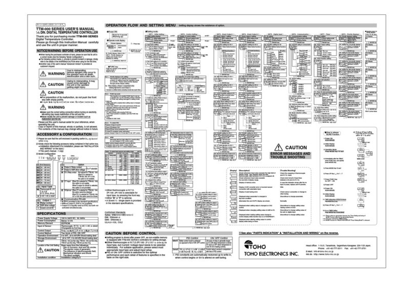
Toho Electronics
Toho Electronics TTM-000 SERIES user manual

Airtopia
Airtopia Control4 Installation and usage instructions
Lake Shore
Lake Shore 335 user manual

Shinko
Shinko RD-500 Series instruction manual

Eurotherm
Eurotherm 2108i Installing and operating instructions
Lowrance
Lowrance EP-80R TH Installation and configuration instructions

Tactical Controls
Tactical Controls 72TS instruction manual
Johnson Controls
Johnson Controls TM-11x1 series installation instructions
