Precision Rated Optics PRO-8CW-35SM User manual

PRO-8CW-35SM
OTDR/ CWDM Channel Analyzer

Tel: (888) 545-1254 • Fax: (415) 358-4602 • Email: Sales@PrecisionRatedOptics.com
www.PrecisionRatedOptics.com
i
1. Using This Manual 1
2. Safety 2
3. Introduction 4
4. PRO-8CW-35SM Quick Start Guide
4.1 OTDR Quick Start Guide.
4.2 CWDM Channel Analyzer-Quick Start Guide
4.3 LTS Quick Start Guide
5
5. Preparation for Use
5.1 Inspection
5.2 Identification and Configuration
5.3 Power Requirements
8
6. Description
6.1 Instrument Description
Instrument Enclosure
Display
Key Pad
Scroll Wheel
6.2 Physical
Front Panel
Top Plate
Bottom Plate
6.3 Home Screen
6.4 Icon Definitions
Setup Icons
OTDR Icons
OTDR Toolbox Icons
Channel
Analyzer Icons
LTS Icons
10
7. General Features and Setup
7.1 General Features
Battery Level/ Power Indicator
USB Flash Drive
USB/PC
7.2 Setup Menu
Set Date and
Time
Brightness
Sound
Baud Rate
Home
15
Contents

Tel: (888) 545-1254 • Fax: (415) 358-4602 • Email: Sales@PrecisionRatedOptics.com
www.PrecisionRatedOptics.com ii
Contents
8. OTDR Operation
8.1 Key Pad Operation
8.2 OTDR Display
Trace Display
Trace Measurements
Trace Parameters
OTDR Display with Menu Open
8.3 OTDR Tools Menu
Resolution
Unit of Measure
Cursor Lock
Loss Mode
Splice Loss
Least Squares
Approximation (LSA)
Enter Calibration
8.4 Auto Test
Range Finder
Construction Mode
Set Wavelengths
Set Tests Parameters
Set File Name
Set Default Notes
Conduct Test
8.5 Manual Scan Settings
Resolution
Index of Refractions (IOR)
Wavelengths
Average (AVG)
Pulse Width
Range
8.6 Viewing a Trace
Zoom
Zoom Bar
Cursor Movement
Cursor Lock
8.7 Unit of Measure
8.8 Loss Measurements
2 Point
Average
dB/Km
17
Splice Loss
Least Squares
Approximation
8.9
Setting Splice Loss Measurement Areas
8.10
Quick Save/Recall
Quick Save
Quick Recall

Tel: (888) 545-1254 • Fax: (415) 358-4602 • Email: Sales@PrecisionRatedOptics.com
www.PrecisionRatedOptics.com
iii
9. Event Analysis
9.2 Event Analysis table
9.3 Event Table Field Descriptions
Event Number (#)
Pass/Field (P/F)
Event Location (KM)
Event Loss (SPLICE)
2 Point Loss (2POINT)
dB Loss per KM, KF or MI (DB/KM)
Event Type/ORL (TYPE)
End Event (E)
9.4 Event Sensitivity Level
9.5 Pass/Fail Settings
28
10. File Management
10.1 File Management Display
10.2 Entering /Exiting File Management
10.3 Saving a Trace
10.4 Renaming a Trace
10.5 Viewing a Saved Trace
10.6 Dual Trace
10.7 Marking Traces for Mass Copy and Deleting
10.8 Copying Traces
10.9 Deleting Traces
10.10 Accessing Flash Drive
10.11 Internal Memory Statistics
31
11. Loss Test Set Description
11.1 Entering Loss test Set Mode
11.2 Key Pad Operation
11.3 Loss Test Set Displays
LTS Live Scan Mode
LTS File View Mode
11.4 LTS Soft Key Operation
Source
Power Meter
Mode
11.5 LTS Icon List
Help
Delete
Lambda (Wavelength Selection)
File Download
Set Reference
dBm/dB
Calibration (CAL)
Exit Application
34
12. Loss Test Set Operation
12.1 Power Meter Measurements
Power Measurements
Relative Measurements
12.2 Auto Test Mode
12.3 Light Source Operations
12.4 File View
12.5 File Transfer
38

Tel: (888) 545-1254 • Fax: (415) 358-4602 • Email: Sales@PrecisionRatedOptics.com
www.PrecisionRatedOptics.com ii
13. Channel Analyzer Operation
13.1 Key Pad Operation
13.2 Channel Analyzer Display
Displayed Scan Measurements
13.3 Enter Channel Analyzer function
13.4 Channel Analyzer Table
13.5 Unit of Measure
13.6 Quick Save/Recall
40
14. Channel Analyzer File Management
14.1 File Management display
14.2 Viewing a stored Scan
14.3 File Management Soft Key Functions
Exit File Management
Copying Files to a Personal Computer
Copying Files to Flash Drive
Naming a File
Renaming a File
Deleting Files
Marking Files
Viewing Scans from a USB Flash Drive
44
15. Video Scope Operation
15.1 Video Scope Display
15.2 Video Scope Operation
15.3 Video Scope Soft Keys
Home
Copy
Save
Recall
Adjust Position/adjust contrast
47
16. Visual Fault Locator (VFL)
16.1 VFL Description
16.2 VFL Operation
49
17. Maintenance
17.1 Battery Replacement
17.2 Calibration
17.3 Adapter replacement
50
18. Specifications
19. Warranty and repair
19.1 Warranty Information
19.2 Repair Information
20. Trouble Shooting Guide
21. Version Control

Tel: (888) 545-1254 • Fax: (415) 358-4602 • Email: Sales@PrecisionRatedOptics.com
www.PrecisionRatedOptics.com
1
Chapter 1 Using This Manual
This Manual contains information for the PRO-8CW-35SM which is an OTDR, CWDM Channel Analyzer,
Broad Band Power Meter, Stable Light Source, Visual Fault Locator and Video Scope contained in one
unit. The beginning of the manual contains general information pertaining to the physical features of the
equipment. Please refer to the appropriate chapters for information on the operation of each individual
function.
There are warnings, cautions and notes annotated through this manual.
Warning
A warning alerts to situations that could cause personal injury.
Caution
A caution alerts to situations that may cause damage to the equipment or produce poor testing
conditions resulting in inaccurate test results.
Note
A special annotation that will assist the user with operational features.

Tel: (888) 545-1254 • Fax: (415) 358-4602 • Email: Sales@PrecisionRatedOptics.com
www.PrecisionRatedOptics.com 2
Chapter 2 Safety
Chapter 3 of this manual is a quick start guide. Prior to using the quick start guide or operating the
equipment in any way, it is highly suggested the user reads all safety information
This product has been designed and tested in accordance with the Manufacturer’s safety standards, and
has been supplied in a safe condition.
This document contains information and warnings that must be followed by the user to ensure safe
operation and to maintain the product in a safe condition. Failure to follow these safety warnings, can
result in damage to the instrument or harm to the user.
Warning
Personnel should always be aware when working with fiber optic test equipment that active fibers
may be present and therefore infrared optical energy may be present.
Warning
Never look directly into the end of a connected fiber optic cable or fiber optic adapter of test
equipment, to do so could expose the user to laser radiation and could result in sever personal injury.
Warning
To Prevent Fire or Shock Hazard
● Do not install battery types other than those specified by the manufacturer
● Do not use the charger without the batteries installed
● Do not expose the battery charger to rain or excessive moisture
● Do not use the AC adapter when there are signs of damage to the enclosure or cord
● Ensure that you are using the correct charger for the local line voltage
● Do not use any other charger than the one provided with this instrument

Tel: (888) 545-1254 • Fax: (415) 358-4602 • Email: Sales@PrecisionRatedOptics.com
www.PrecisionRatedOptics.com
3
Failure to follow these cautions statements may void the warranty of this equipment.
Caution
Fiber-optic connectors are easily contaminated or damaged. The connection to the PRO-8CW-35SM
is a physical contact type of connection and dirty or damaged connectors may impair the instruments
capabilities at minimum and at worst result in the need to return this unit to the factory for expensive
repairs. Prior to making any connection to the unit, ensure that all proper cleaning procedures have
been followed. Use UPC Finish Connectors Only!
Caution
The PRO-8CW-35SM-CWDM maximum power per channel is +5dBm and the Maximum Composite
power is +23dBm. Attempting to test greater power levels will cause damage to this instrument.
Chapter 2 Safety

Tel: (888) 545-1254 • Fax: (415) 358-4602 • Email: Sales@PrecisionRatedOptics.com
www.PrecisionRatedOptics.com 4
Chapter 3 Introduction
Thank you for purchasing the PRO-8CW-SM35 multi-tasker, the world’s first handheld test and
measurement product dedicated to assist you with installation, commissioning and maintenance of the
next-gen fiber optic networks. If you’re working with upgrading an overburdened network with additional
optical channels or installing the latest generation of multichannel high bandwidth fiber links, the multi-
tasker will assist with meeting your test and measurement needs quickly and efficiently.
The PRO-8CW-SM35 includes the latest extended dynamic range, high resolution Optical Time Domain
Reflectometer (OTDR) technologies as the base platform. As with all of PRO’s newest developments, we
have incorporated the standard features including Instant-on, autotest and immediate event analysis for
fast and trouble free visibility of network distance and loss measurements. Also this instrument includes
the standard capabilities of the stabilized singlemode light source with autowave capability, the matching
autowave broadband power meter to complete the Loss Test Set (LTS) function, a visible fault locator
(VFL) source for nearby fault isolation and fiber identification, and the video scope option for end face
analysis. New to the PRO-8CW-SM35 is the inclusion of the 8 channel ITU grid multi spectrum (OSA)
power analyzer for simultaneous measurement of the upper 8 CWDM wavelengths utilized in the latest
high bandwidth networks.
The multi-tasker provides a startup menu to select from the OTDR, VFL, LTS, SCOPE, and OSA function
immediately upon energizing. This feature is coupled to each instrument for immediate analysis of
important features of your link. Before connecting the instrument to your fiber under test, it is good
practice to examine the optical patch connectors with the optional high resolution 200x or 400x video
scope probe and collect an image to attach to your link documentation. For basic link analysis the OTDR
can then be connected and an autotest can immediately provide link loss and distance results on single
mode fiber at the popular 1310nm and 1550nm wavelengths. The construction mode can be selected to
automatically collect and file both fiber signatures.
The on-board Loss Test Set completes the standard package of documented results necessary to
commission a system, or can be utilized for pass fail analysis of network power throughput. The
advanced autowave feature is a must to improve the efficiency and reliability of measuring at both
1310nm and 1550nm radiation, but as a broadband power meter it is calibrated for system end to end
loss analysis at all popular fiber optic wavelengths with your sources.
For commissioning or troubleshooting a multi-wavelength system, the 8 channel CWDM can be utilized
at various points to detect proper power levels from each source and appropriate add/drop connectivity
settings at each adjustable node on the network. The channel analyzer provides immediate real time
power measurement results of all 8 channels from 1471nm to 1611nm simultaneously and also analyzes
and displays statistical measurements at each ITU grid channel. Of course documentation of all these
results is accomplished at the push of a button.
PRO has many advanced measuring instruments for use with multiple wavelength multimode and
singlemode systems from CWDM wavelength OTDR analyzers, DWDM MiniOSA devices, DWDM Tunable
Laser sources, Variable Optical Attenuators, Loss Test Sets, Video Scopes, as well as PON OTDRs with
1625nm active out-of-band coverage. Please enjoy the use of your new PRO-8CW-SM35 multi-tasker, and
again thank you for considering PRO. Please follow the next section’s simple startup instruction to get
right to work with your PRO test and measurement equipment.
Tel: (888) 545-1254 • Fax: (415) 358-4602 • Email: Sales@PrecisionRatedOptics.com
www.PrecisionRatedOptics.com
5
Chapter 4 Quick Start Guides
4.0 Quick Start Guides
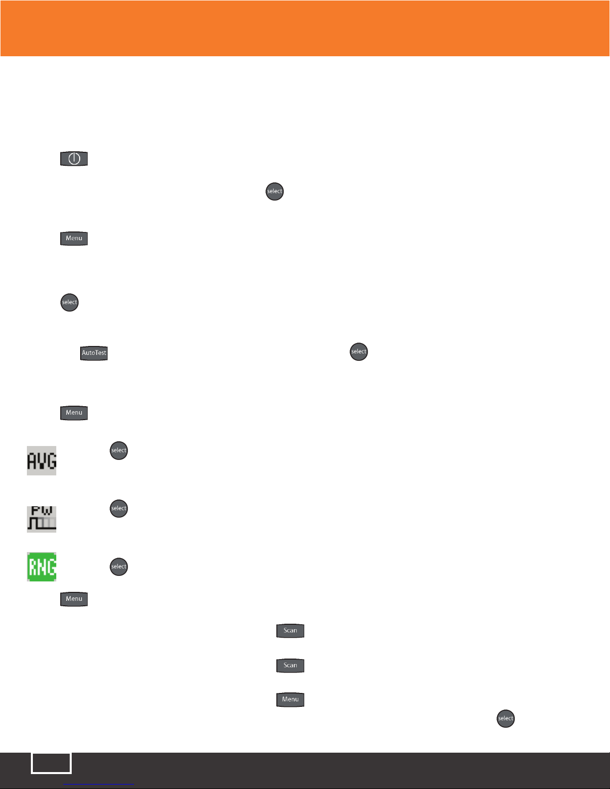
4.1 OTDR Quick Start Guide
Press to turn on the OTDR.
The OTDR function will be highlighted. Press to initiate the OTDR application. Connect the fiber to
the appropriate port. (Select Multi Mode or Single Mode if OTDR is a quad wavelength unit)
Press to enter the Menu mode.
Use the Scroll Wheel to highlight the [ λ ] in the icon list.
Press to cycle to the desired wavelength. The OTDR will start a scan at the parameters displayed. If
approximate fiber length is not known:
Press the button after selecting the wavelength, (Press on Range Finder) the Auto Test feature
will start and set an appropriate pulse width and range automatically. If approximate fiber length is
known:
Press and scroll to:
Press to cycle through the averaging times of - R/T for real-time, Short for a 10 second
average time or Long for a 5 minute averaging time.
Press to cycle through the pulse width - select 2m for fibers up to 4 kilometers, 10m or fiber
up to 16 kilometers, 100m for fibers up to 64 kilometers or 1k for fibers up to 240 kilometers.
Press to toggle between to available range settings.
Press to exit the menu mode.
To manually start a scan: Press while the unit is idle.
To stop a scan: Press while the unit is scanning.
To view the Event table:
Press to enter Menu mode and use the Scroll Wheel to
highlight the Show Event soft key and press the button to
change to the event analysis mode
Tel: (888) 545-1254 • Fax: (415) 358-4602 • Email: Sales@PrecisionRatedOptics.com
www.PrecisionRatedOptics.com 6
Chapter 4 Quick Start Guides
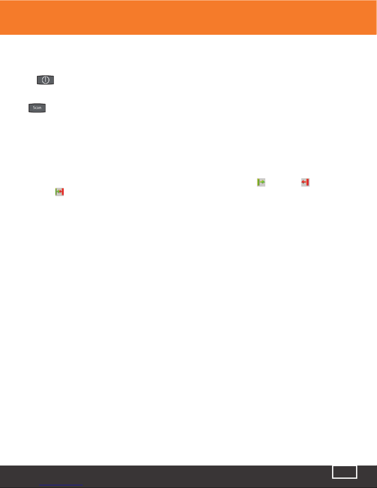
4.2 CWDM Channel Analyzer Quick Start Guide
Press to turn on the PRO-8CW-35SM
Using UPC finish connectors only, connect the fiber to be tested to the “CWDM Optical Port” and press
the button to start a scan.
Note
There is an activity indicator in the bottom left of the display, (see figure.8.3) When the indicator is
red, the unit is ready to scan, to start scanning, press the Scan button. When the Channel Analyzer is
scanning, the activity indicator will be green
The number of channels displayed may be limited by using the Span Start , Span End or
Span Zoom features. These features are fully described in section 8.4 of this manual.
Note
Scale Minimum Power and Span Minimum power are not applicable on the PRO-8CW-35SM-CWDM
Channel Analyzer.

Tel: (888) 545-1254 • Fax: (415) 358-4602 • Email: Sales@PrecisionRatedOptics.com
www.PrecisionRatedOptics.com
7
4.3 Loss Test Set Quick Start Guide
Press to turn on the OTDR.
Use the Scroll Wheel to highlight the LTS function icon and press .
Connect a properly prepared reference cord to the power meter port and the light source port. (If the
unit is a quad wavelength unit, ensure the proper port is connected)
Press and use the Scroll Wheel to highlight the Source soft key at the top left of the display.
Press to energize the first wavelength. Once stabilized, use the Scroll Wheel to highlight the
icon on the right side of the display. Press to set the reference for that wavelength. If a second wave
length is going to be tested, scroll back to the Source soft key and press to cycle to the next desired
wavelength and repeat the step to set the reference.
Press to exit the Menu mode
To conduct a Manual Test
If using the OTDR as the light source, perform
reference procedure as above and place fiber
under test in line between the reference cord
and the power meter port. Ensure you are in
Menu mode and Scroll to Source soft key.
Press to cycle through the wavelengths
and choose the wavelength to be tested.
Press to exit Menu mode.
Press to store the measurement to the
location indicated in the bottom left of the
display
To conduct an Auto Test
Note: Setting a reference in Auto Test mode is
not necessary. The source is modulated and a
Reference of -3dBm (-6dBm-1625) is assumed.
Connect fiber to be tested, press the
button and the light source will cycle to test each
wavelength, the power meter will read the signal
and hold test in temporary memory until the
button is pressed and the test is stored into the
memory location indicated at the bottom left
corner of the display.
Ensure that the unit has cycled through all the
desired wavelengths prior to pressing the select
button.
Auto Test will be displayed at the bottom of the
display to indicate the Auto Test Mode.
Chapter 4 Quick Start Guides

Tel: (888) 545-1254 • Fax: (415) 358-4602 • Email: Sales@PrecisionRatedOptics.com
www.PrecisionRatedOptics.com 8
Chapter 5 Preparation For Use
5.3 Inspection
Before shipment, this instrument was inspected and found to be in perfect working order and
free of defects.
The shipping carton contains the following:
1. Hand Held OTDR/OSA, with protective boot and 8-AA NiMH batteries installed
2. Universal AC/DC charger with interchangeable mains
3. USB cable
4. Manual on CD with Windows™ compatible software and user’s manual
5. Set of interchangeable adapters, SC and FC, for each OSA port.
5.2 Identification and Configuration
The instrument’s Model/Part Number, Serial
Number and Date of Manufacture are indicated on
a label located on the bottom plate of the unit. The
instrument’s history is filed at the factory by model/
part number and serial number.
5.3 Power Requirements
The PRO-8CW-35SM is equipped with a 100-240V-0.4A input and 13.6V, 0.75A, center positive output
universal AC/DC battery charger. This charger is supplied with interchangeable mains for US, Great
Britain, Europe and Australia The unit is shipped with 8-AA NiMH batteries (2700mA hours). Depending
on usage, fully charged battery pack will typically enable approximately 8 hrs. of use. Fully discharged
batteries require 6 - 8 hours of recharging.
Fig 5.1

Tel: (888) 545-1254 • Fax: (415) 358-4602 • Email: Sales@PrecisionRatedOptics.com
www.PrecisionRatedOptics.com
9
5.3 Power Requirements (Continued)
Battery replacement is not recommended; however, if you must replace the batteries, follow this
procedure. Unplug external power supply and ensure the unit is turned off. Carefully remove unit from
protective boot and remove the two screws from top plate and bottom plates that retain the back cover.
Carefully remove back cover and remove the two screws that hold the battery covers in place. Replace
only with 8 high quality AA NiMH batteries. Do not use batteries that are rated at less the 2500mAh. If
you install NiMH batteries that are dead or less than 1 volt each, charge these batteries for one (1) hour
before using the unit. For maintenance, batteries require a monthly periodic recharge.
Warning
To Prevent Fire or Shock Hazard:
● Do not install battery types other than those specified by the manufacturer
● Do not use the charger without the batteries installed
● Do not expose the battery charger to rain or excessive moisture
● Do not use the AC adapter when there are signs of damage to the enclosure or cord
● Ensure that you are using the correct charger for the local line voltage
● Do not use any other charger than the one provided with this instrument.
Failure to follow these caution statements may void the warranty of this equipment.
Chapter 5 Preparation For Use

Tel: (888) 545-1254 • Fax: (415) 358-4602 • Email: Sales@PrecisionRatedOptics.com
www.PrecisionRatedOptics.com 10
Chapter 6 Description
6.1 Instrument Description
Instrument Enclosure
The FTE7800 is packaged in a rugged aluminum housing which is further protected with a rubberized
boot. Although the front panel is weather resistant, care must be taken to avoid liquids and contaminants
around the fragile optical and electrical connectors, and the glass display. Use a mild cleaning agent
and damp soft cloth to clean up the panels and the outside case. See the maintenance section to clean
the optical connector. NEVER open the instrument for cleaning. Return to the factory for servicing if
necessary.
Display
This units is equipped with a 4” color TFT display
Key Pad
The FTE7800 is equipped with a 7 button key pad. For a full description of functions, please see the
section of the manual that is dedicated to function being operated.
Scroll Wheel
The scroll wheel is used to navigate through menus, move cursors and make adjustments to settings
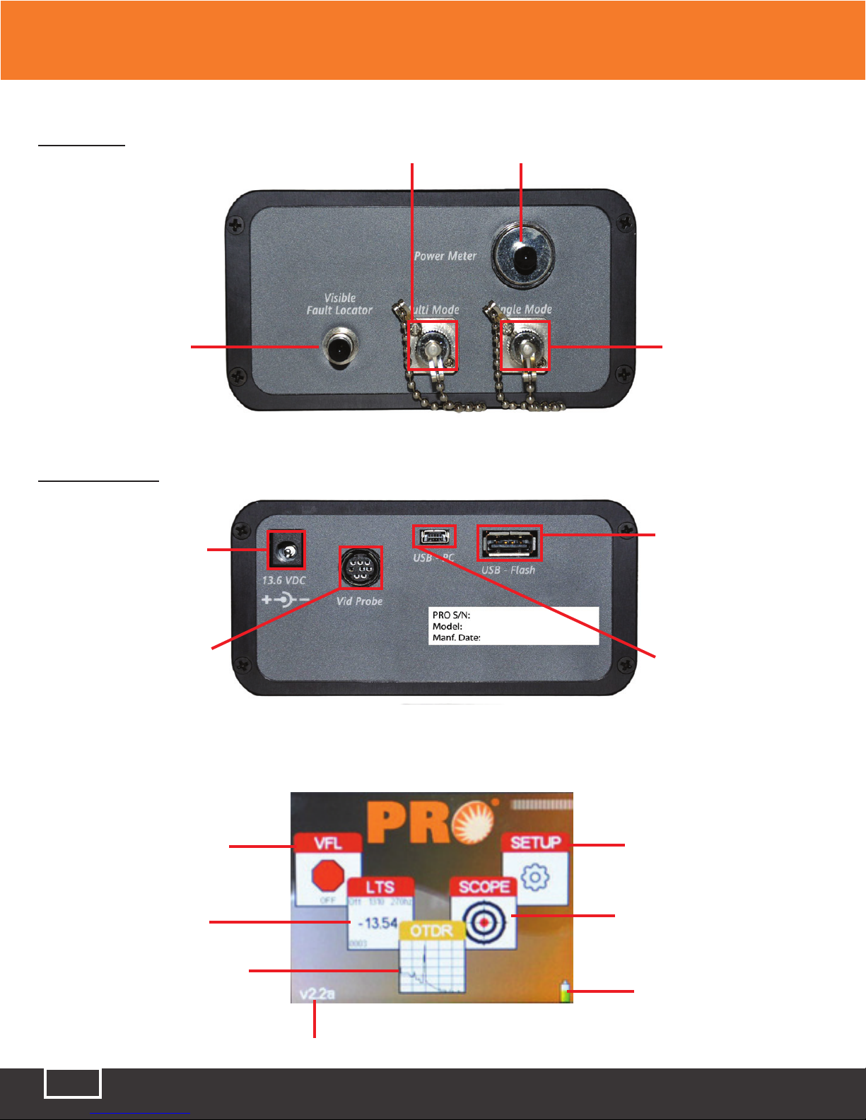
6.2 Physical
Front Panel
Display
Key Pad
Charge Indicator
Scroll Wheel
Fig 6.1
Tel: (888) 545-1254 • Fax: (415) 358-4602 • Email: Sales@PrecisionRatedOptics.com
www.PrecisionRatedOptics.com
11
Top Plate CWDM PORT Power Meter PORT
VFL PORT OTDR Port
Bottom Plate
Power Jack
Video Probe Port
USB Flash
USB PC Port
Fig 6.2
6.3 Home Screen
Visual Fault
Locator Button
Loss Test
Set Button
Optical Time Domain
Reflectometer Button
Optical Spectrum
Analyzer Button
Version Number
Video Scope Button
Battery Level
Indicator
Fig 6.4
Chapter 6 Description
Fig 6.3

Tel: (888) 545-1254 • Fax: (415) 358-4602 • Email: Sales@PrecisionRatedOptics.com
www.PrecisionRatedOptics.com 12
6.3 Icon Definitions
6.3 Icon Definitions
The list below and on the next page contain the icons found on the PRO-8CW-35SM units. They control
features and functions, and allow the user to set testing parameters. This table gives the name and a
brief explanation of each. More detailed explanations will be found in later sections of this chapter and in
chapters to follow.
Setup Icons
Date/Time Used to set the time/date
Back Light Toggles on and off the back light
Speaker Toggles on and off the speaker
Baud Rate Used to manually set the baud rate for USB/PC communications
Home Returns the user to the Home Menu
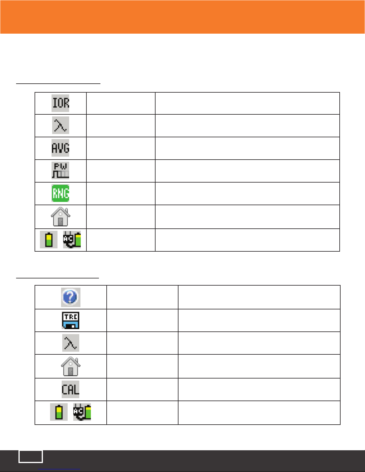
OTDR Icons
Help Feature Accesses the help files
LSA Adjustments Used to adjust the LSA splice loss areas
File Management Used to enter the File Management
Tool Box The Tool Box contains equipment features, and operational
parameters that are seldom changed
OTDR Toolbox Icons
Resolution Used to set the OTDR to Low or High Resolution
Unit of Measure Use to set the Unit of Measure to Kilometers, Kilofeet or Miles
Cursor Lock Used to Lock the “A” and “B” cursors movement
Loss Mode Used to Select Splice or LSA loss modes or to disable the loss mode
Calibration This is reserved for factory use
Chapter 6 Description
Tel: (888) 545-1254 • Fax: (415) 358-4602 • Email: Sales@PrecisionRatedOptics.com
www.PrecisionRatedOptics.com
13
6.3 Icon Definitions (continued)
OTDR Icons (continued)
Index of Refraction Used to set the Index of Refraction from 1.024 - 2.048
Lambda Cycles through the wavelengths available for use on the OTDR
Average Cycles through the average mode available
Pulse Width Cycles through the available pulse with for a selected range
Range Cycles through the available ranges on the OTDR
Home Returns the user to the Home Menu
Battery Icons Indicates the charge status of the batteries. When operating on AC
power, an AC plug will be displayed next to the battery.
Channel Analyzer Icons
Help Feature Accesses the help files
File Management Used to enter the File Management
Lambda Used to change channel measurements to wavelength or
frequency
Home Returns the user to the Home Menu
Calibration This is reserved for factory use
Battery Icons
Indicates the charge status of the batteries. When
operating on AC power, an AC plug will be displayed next to
the battery
Chapter 6 Description

Tel: (888) 545-1254 • Fax: (415) 358-4602 • Email: Sales@PrecisionRatedOptics.com
www.PrecisionRatedOptics.com 14
6.3 Icon Definitions (continued)
LTS Icons
Help Feature Accesses the help files
File Delete Delete Loss Test Set files
File Download Download File to the computer via USB cable
Lambda Used to filter power meter wavelengths out of Autotest Mode.
Reference Used to set nonvolatile reference
dBm/dB Used to set measurement unit to dBm or dB
Calibration This is reserved for factory use
Home Returns the user to the Home Menu
Battery Icons Indicates the charge status of the batteries. When operating on
AC power, an AC plug will be displayed next to the battery.
Chapter 6 Description

Tel: (888) 545-1254 • Fax: (415) 358-4602 • Email: Sales@PrecisionRatedOptics.com
www.PrecisionRatedOptics.com
15
Chapter 7 General Features and Setup
7.0 General Features and Setup
7.1 General Features
Battery Level/Power Indicator
The bottom right hand corner of the screen shows the battery level indicator. In the final hour of
operation the battery will change to red. A warning indicator will sound a few minutes before the
instrument automatically turns off. An AC plug will be displayed next to the indicator bar if the unit is
operating with the AC power supply/charger. There is also a red charge light in the top right corner of the
front panel. This will glow red when the unit is charging.
Caution
Ensure the unit is turned off before plugging or unplugging the AC power supply/charger.
USB Flash Drive
Located on the bottom panel is the USB Flash Drive port. Scan file and Scope files may be downloaded
the external memory device. Screen Shots are downloaded directly to the USB flash drive.
Note
Flash drives of 4 GB or less are supported
USB/PC
Located on the bottom panel is the USB/PC port which may be used to connect the Optical Spectrum
Analyzer to a computer to download stored data for analysis with the supplied Windows™ compatible
software.
7.2 Setup Menu
The following features are accessed from the setup menu. To access the setup menu, press the Menu
button while on the Home Screen. To exit the setup menu at any time press the Menu button again.
Set Date and time
The PRO-8CW-35SM applies a time/date stamp to the saved Scans. The date is configured MM/DD/YY
and the time is a 24 hour format set in the eastern time zone. To change the data and time, Press the
Menu button to enter the menu mode, scroll to the Clock icon and press the Select button. The dialog box
with the settings will be displayed. Use the scroll wheel to change each segment, use the Select button to
move between segments, and to Save/Redo/Cancel. Use the scroll wheel to select Save, Redo or Cancel
then press the Select button again to complete setting the date and time. This setting has a memory of
approximately one month of no instrument activity. To recharge the memory, turn the instrument on for
5 minutes per month or during the monthly battery charge if the unit is not used for a long period.
Table of contents
Other Precision Rated Optics Measuring Instrument manuals


Popular Measuring Instrument manuals by other brands

Rigol
Rigol DSG3030-IQ user guide

Fluke
Fluke 317 manual

Extech Instruments
Extech Instruments HDV7C-55-HD-1 user manual

MyWindFit
MyWindFit Meter instructions

Dwyer Instruments
Dwyer Instruments TUF series Specifications-installation and operating instructions

Bante Instruments
Bante Instruments TB100 user manual


 Operation manual")

