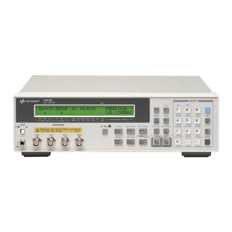
Tegam 3525 User manual

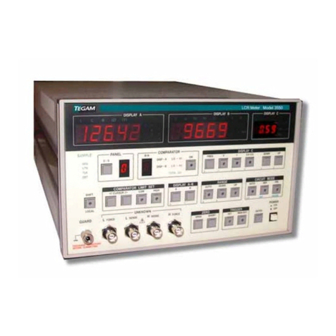
MODEL 3525
GENERAL-PURPOSE, PROGRAMMABLE
LCR METER
Instruction Manual
PN# 3525-900-01CD
Publication Date: February 2009
REV. E

Table of Contents
Model 3525 LCR Meter Instruction Manual a
TEGAM INC.
MODEL 3525
GENERAL-PURPOSE, PROGRAMMABLE
LCR METER
MODEL 3525
Instruction Manual
PN# 3525-900-01CD
Publication Date: February 2009
REV. E
NOTE: This user’s manual was as current as possible when this product was manufactured. However, products are
constantly being updated and improved. Because of this, some differences may occur between the description in this
manual and the product received.

Table of Contents
Model 3525 LCR Meter Instruction Manual b
I INSTRUMENT DESCRIPTION............................................................................1-1
Instrument Description ........................................................................... 1-2
Feature Overview................................................................................... 1-2
Accessories Sheet .................................................................................. 1-4
Performance Specifications...................................................................... 1-5
Measurement Ranges......................................................................... 1-5
Table 1.1 - Absolute Impedance Range Limits Chart............................... 1-5
Display A & B – Basic Accuracies ......................................................... 1-6
Table 1.2 – Basic Accuracy for Display A............................................... 1-6
Table 1.3 – Basic Accuracy for Display B............................................... 1-6
Calculating Actual Measurement Accuracies........................................... 1-7
Table 1.4 – Speed Coefficient.............................................................. 1-7
Table 1.5 – Amplitude Coefficient ........................................................ 1-7
Instrument Specifications........................................................................ 1-8
II PREPARATION FOR USE ..................................................................................2-1
Unpacking & Inspection........................................................................... 2-2
Safety Information & Precautions ............................................................. 2-2
Terms in this Manual ......................................................................... 2-2
Terms as Marked on Equipment........................................................... 2-2
Symbols........................................................................................... 2-3
Grounding the Equipment................................................................... 2-3
Danger Arising from the Loss of Ground ............................................... 2-3
Use the Proper Fuse...........................................................................2-4
Do not Use in Explosive Environments.................................................. 2-4
Do not Operate without Covers ........................................................... 2-4
Servicing Safety Summary ...................................................................... 2-4
Do not Service Alone ......................................................................... 2-4
Use Care when Servicing with Power On............................................... 2-4
Power Source ................................................................................... 2-4
Line Voltage Selection............................................................................. 2-5
Table 2.1 – Operating Voltage Ranges.................................................. 2-5
III QUICK START INSTRUCTIONS.........................................................................3-1
Power the Unit....................................................................................... 3-2
Factory Default Settings.......................................................................... 3-2
Table 3.1 - Factory Default Settings..................................................... 3-2
Instrument Setup................................................................................... 3-3
Display A ......................................................................................... 3-3
Display B ......................................................................................... 3-3
Measurement Speed.......................................................................... 3-3
Test Frequency ................................................................................. 3-3
Test Voltage Level............................................................................. 3-3
Circuit Mode ..................................................................................... 3-3
Range.............................................................................................. 3-3
Trigger ............................................................................................ 3-3
Performing an Open and Short Circuit Null................................................. 3-4
Measurement Tips.................................................................................. 3-4

Table of Contents
Model 3525 LCR Meter Instruction Manual c
IV OPERATING INSTRUCTIONS............................................................................4-1
Basic Operation...................................................................................... 4-2
Default Parameters................................................................................. 4-2
Front Panel Description ........................................................................... 4-3
Figure 4.1a – Front Panel Layout ......................................................... 4-3
Figure 4.1b – Measurement & Parameter Control Area............................ 4-4
Figure 4.1c – Comparator Controls Area ............................................... 4-5
Rear Panel Description............................................................................ 4-6
Figure 4.2 – Rear Panel...................................................................... 4-6
Selecting the Measurement Parameters..................................................... 4-7
Table 4.1a – Display A Description of Measurement Functions.................. 4-7
Table 4.1b – Display B Description of Measurement Functions.................. 4-7
Setting the Measurement Speed............................................................... 4-8
Table 4.2 – 3525 Typical Measurement Times........................................ 4-8
Setting the Measurement Frequency ......................................................... 4-9
Setting the Measurement Signal Level....................................................... 4-9
Setting the Equivalent Circuits Mode ......................................................... 4-10
Setting the measurement Range .............................................................. 4-11
Table 4.3 – Measurement Range Characteristics .................................... 4-11
Setting the Trigger Mode......................................................................... 4-13
Using the Comparator Functions............................................................... 4-14
Overview ......................................................................................... 4-14
Table 4.4 – Operation of GO/NO-GO Comparator ................................... 4-14
Setting the High and Low Limit Values.................................................. 4-15
Preset Panel Function.............................................................................. 4-18
Overview ......................................................................................... 4-18
Setting Panel Numbers....................................................................... 4-18
Recalling Panel Numbers .................................................................... 4-18
Zero Correction...................................................................................... 4-19
Overview ......................................................................................... 4-19
Figure 4.3 – Terminal Connections for Zero Correction............................ 4-19
Open Circuit Correction ...................................................................... 4-20
Short Circuit Correction...................................................................... 4-20
Audible Beeper ...................................................................................... 4-21
Overview ......................................................................................... 4-21
Setting the Beep Sound...................................................................... 4-21
Connection Methods ............................................................................... 4-22
Figure 4.4 – 3 Terminal Connection...................................................... 4-22
Figure 4.5 – 5 Terminal Connection...................................................... 4-23
V PROGRAMMING & INTERFACING.....................................................................5-1
Interfacing to the 3525 ........................................................................... 5-2
Front Panel Connections.......................................................................... 5-2
Figure 5.1 – Front Panel Measurement Connections................................ 5-2
Rear Panel ............................................................................................ 5-3
Figure 5.2 – Rear Panel Interfaces....................................................... 5-3

Table of Contents
Model 3525 LCR Meter Instruction Manual d
V PROGRAMMING & INTERFACING cont’d
I/O Control Connector............................................................................. 5-4
Compatible Connectors ...................................................................... 5-4
I/O Pin Outputs................................................................................. 5-4
Figure 5.3 – I/O Control Connector Pin Orientation................................. 5-4
Table 5.1 – Pin Designations............................................................... 5-5
I/O Pin Descriptions........................................................................... 5-5
Table 5.2 – BCD Panel Settings ........................................................... 5-6
Table 5.3 – Total Go & No Go Functional Relationships............................ 5-7
I/O Control Connector Electrical Schematic ........................................... 5-8
Figure 5.4 – I/O Control Connector Schematic....................................... 5-8
I/O Timing Diagrams .............................................................................. 5-9
Figure 5.5 – I/O Control Connector Timing Diagram ............................... 5-9
Approximate Measurement Times............................................................. 5-9
Table 5.4 – Approximate Measurement and Signal Processing Times......... 5-9
Analog Signal Measurement Time ........................................................ 5-10
Table 5.5a – Analog Signal Measurement Time...................................... 5-10
Measurement Speed.......................................................................... 5-10
Table 5.5b – Total Measurement Speed ................................................ 5-10
RS232C Communications ........................................................................ 5-11
Figure 5.6 – RS-232C Connector ......................................................... 5-11
Table 5.6 – RS-232C DTE Pin Configurations ......................................... 5-11
RS-232C Settings.............................................................................. 5-12
Remote Commands ................................................................................ 5-13
Program Messages ............................................................................ 5-13
The Header ......................................................................................5-13
The Parameter.................................................................................. 5-13
Rules for Remote Commands .............................................................. 5-14
Rules for Commands and Parameters................................................... 5-14
Condition & State Registers ................................................................ 5-15
Commands List................................................................................. 5-18
Table 5.7 – RS-232C & GPIB Command Set .......................................... 5-18
Command Reference.......................................................................... 5-19
VI SERVICE INFORMATION..................................................................................6-1
Warranty .............................................................................................. 6-2
Warranty Limitations .............................................................................. 6-2
Statement of Calibration ......................................................................... 6-2
Contact Information ............................................................................... 6-2
Repair Parts .......................................................................................... 6-3
Changing the Power Fuse ........................................................................ 6-3
Preparation for Calibration or Repair Service .............................................. 6-4
Expedite Repair & Calibration Form...................................................... 6-5
Model 3525 Verification Procedure............................................................ 6-6
VI APPENDIX .......................................................................................................A-1

Instrument Description
INSTRUMENT DESCRIPTION
PREPARATION FOR USE
QUICK START INSTRUCTIONS
OPERATING INSTRUCTIONS
PROGRAMMING & INTERFACING
SERVICE INFORMATION
APPENDIX
Model 3525 LCR Meter Instruction Manual 1-1

Model 3525 LCR Meter Instruction Manual Instrument Description
1-2
Instrument Description
Model 3525,TEGAM’s innovative solution for cost sensitive LCR applications, does not compromise
quality or performance. Its flexible design allows a diverse range of testing applications including
manual or automated testing of capacitors, inductors, coils, resistors, thermoelectric cooling
devices, materials, piezo-electric or other sensors or components possessing AC impedance
characteristics.
Up to 9 impedance parameters are easily viewed on each of the 3525’s two 4 ½ digit, LED
displays. Display A provides accurate and repeatable readings of Inductance (L), Capacitance (C),
Resistance (R), and Impedance (|Z|). Display B measures values for Dissipation Factor (D or Tan
δ), Quality Factor (Q), Phase Angle (θ), Measurement Voltage (V) and Measurement Current (I).
All parameters are easily monitored, selectable from the front panel, and may be measured as
Series or Parallel equivalent circuits.
The 3525’s compact size is unprecedented and allows side-by-side mounting in standard 19”
racks. A built-in comparator function makes the 3525 the ideal choice for manual component
checking. Whether you are verifying component values for QA or manufacturing, the built in GO-
NO GO comparator reduces test time and increases productivity with an audible beeper that may
be set to alarm when a pass or fail state has been measured. A front panel lock feature prevents
accidental changes on instruments settings.
Model 3525 is shipped from the factory with standard Kelvin Klips, RS-232C port, and I/O
connector. There are a variety of optional accessories available, including GPIB Interface, BCD
Output, Kelvin Klip Leads, Kelvin Tweezers, Radial Sorting Fixture, and SMT Chip Test Fixture. See
the Accessories Sheet on page 1-4 for complete descriptions.
Feature Overview
The Model 3525 was designed with the right balance of features to keep cost down while
providing optimal performance for most basic LCR applications. Below is a summary of the
instrument’s main features.
0.08% Basic Accuracy with 4.5 digit resolution.
The 3525 is designed to perform basic impedance measurements with up to 0.08% basic
accuracy. Measurement accuracies are dependent upon a number of parameters and test
conditions. See Performance Specifications to determine the actual measurement
accuracies.
High Speed Measurement
With a 1kHz test frequency a reading can be obtained in as little as 15 mS when the
instrument is operating in fast mode.
Manual or Remote Operation
The 3525 is equipped for manual or remote operation. Standard interfaces include a RS-
232C and I/O port. GPIB and BCD interfaces are available as optional accessories.

Model 3525 LCR Meter Instruction Manual Instrument Description
1-3
Feature Overview cont’d:
Dual High Intensity Displays
The 3525 is equipped with dual LED displays for easy viewing. Display A measures 4½
digits of Inductance (L), Capacitance (C), Resistance (R), or Impedance (|Z|) while Display
B indicates Dissipation Factor (D or Tan δ), Quality Factor (Q), Phase Angle (θ),
Measurement Voltage (V), or Measurement Current (I).
Programmable GO/NO-GO Comparator with Audible Buzzer
Each unit has an internal comparator function that can be set by the user. Comparator
Outputs result from the values of Display A, Display B, or a combination of the two. The
comparator outputs may be read from the front panel, buzzer, the I/O connector located
on the rear panel, or queried from the remote interfaces.
99 Preset Storage Locations
Panel Settings 01-99 are user-definable and may be programmed manually or via
communication interfaces. These settings are stored in non-volatile RAM locations and may
be recalled from the front panel or any of the rear interfaces.
Less than ½ Rack Width
Two 3525 units are able to be rack mounted, side-by-side, in a standard 19” rack using a
third party rack mount kit, without modifying the instrument cases.
Manual or Auto Ranging
In AUTO range, the instrument automatically selects from 10 different impedance ranges.
The selected range is dependent upon the DUT’s absolute impedance, |Z|. In the manual
range mode, the user may select from any of these ten ranges through the front panel.
Voltage and Current Monitors
Test Voltage (Vx) and Current (Ix) can be measured at the DUT terminals and are
viewable on Display B to three significant digits.
Open and Short Circuit Zero Correction
Parasitic impedance of the test cables and/or test fixture may be cancelled out by
performing the 3525’s auto zero functions.
Front Panel Lock
The 3525 is equipped with a front panel lock-out feature to prevent accidental changes to
instrument settings.
Dual Trigger Modes
Trigger instructions may be executed either internally or externally. Internal triggering
allows the instrument to run continuously while external triggering requires instruction
from the front panel, I/O connector, RS-232C, or GPIB interfaces.
Series or Parallel Equivalent Measurements
AC parameters may be measured as Series or Parallel equivalents.

Model 3525 LCR Meter Instruction Manual Instrument Description
1-4
3525 Accessories Sheet
2005B - Chip Tweezers (5ft)
This four-terminal tweezer set
makes solid connections to chip
components in manual sorting
applications. Capacity of jaws is
12.7mm (0.5 in.). The 2005B Chip
Component Tweezer Set includes a
1.5m (5 ft) cable for connection to
the 3525. Contact tips are
replaceable. P/N 47422.
47422 Chip Tweezer
Replacement Kit
Tweezer tips are intended to last
100,000 to 500,000 operations. An
optional tip replacement kit includes
12 replacement tips, 2 screws and 1
wrench.
3511 - Chip Test Fixture
Available for performing three
terminal measurements on surface
mount devices. Connects directly to
the front panel of the 3525. Use the
3511 for medium and high
impedance measurements.
3525-900-01CD – Instruction
Manual
Printed copy of the 3525 users
manual.
3510-Radial Lead Adapter
This sorting fixture allows for efficient
four-wire measurement of leaded parts.
The test fixture features spring action
contacts for easy insertion and removal of
test components.
47454 – Kelvin Klips
Kelvin Klips allow solid four-terminal,
Kelvin connections to leaded components.
The jaws are assembled with hardened
gold-plated, beryllium copper, which
ensures low contact resistance, low
thermal emf to copper, high corrosion
resistance, and long service life. An
alligator clip is provided allowing
connection of a passive guard. The
assembly includes a 5 ft (1.5m) cable for
connection to the 3525.
NOTE: Under certain measurement conditions,
Kelvin Klips can cause a loss of measurement
accuracy. Fixtures 3510, 3511, or 2005B chip
tweezers are recommended for the following
component values:
C<100pF; L < 100μH; R > 1MΩ
CBL-3102-BNC-BNC Cable
BNC to BNC, RG 58/U, coaxial cable for
use at the trigger inputs and outputs of
the 3525. Cable length is a minimum of 1
meter (3.28 ft) long.
KK100- Kelvin Klip™ Rebuild
Kit
Kelvin Klip™ replacements for
construction or repair of Kelvin Klip
leads.
GPIB (IEEE-488) Cables
1583-3 – 1-meter GPIB buss cable
1583-6 – 2-meter GPIB buss cable
1583-9 – 3-meter GPIB buss cable
3502 – BCD Interface
BCD output for interface to handlers
and other automated systems.
3501 – GPIB Interface
GPIB (IEEE-488)-compatible interface
card. Field or factory installation.
740565 – CABLE NULL
740565-6 – 6’ cable, null mod, 9-9
740565-10 – 10’ cable, null mod, 9-9

Model 3525 LCR Meter Instruction Manual Instrument Description
1-5
Performance Specifications
The advertised specifications of the Model 3525 are valid under the following conditions:
1. The instrument’s calibration must be verified using the methods and intervals as described
in the Service Information Section of this user’s manual.
2. The instrument must be in an environment which does not exceed the limitations as
defined under “Environmental” in the Instrument Specifications section.
3. The unit is allowed to warm up for a period of at least 30 minutes before measurements
are taken. A warm-up period of 60 minutes is recommended after exposure to or storage
in a high humidity, non-condensing environment.
4. Use only TEGAM-manufactured test leads and sorting fixtures with this device. Modification
of existing test cables or fixtures may compromise the accuracy of your readings. Always
perform an open and short zero null procedure before taking measurements.
Measurement Ranges
Table 1.1: Absolute Impedance Range Limits Chart
Range No. |Z| Measurement Range
1 0.0100Ω~ 0.1999Ω
2 0.1800Ω~1.9999Ω
3 1.800Ω~ 19.999Ω
4 20.00Ω~ 199.99Ω
5 0.2000kΩ~ 1.9999kΩ
6 2.000kΩ~ 19.999kΩ
7 20.00kΩ~ 199.99kΩ
8 0.1800MΩ~ 1.9999MΩ
9 2.000MΩ~ 19.999MΩ
10 18.0MΩ~ 199.99MΩ
The measurement range is determined by the absolute impedance, |Z| of the DUT. The absolute
impedance includes the vector sum of L, C, and R values.

Model 3525 LCR Meter Instruction Manual Instrument Description
1-6
Display A & B - Basic Accuracies
Table 1.2: Basic Accuracy for Display A
Range L C R Z
1 ±(0.90+30/fL1)% ±(0.60+1.5fC1)% ±(1.00+0.21/R1)% ±(1.00+0.15/Z1)%
2 ±2.10% ±2.10% ±2.10% ±1.80%
3 ±0.39% ±0.39% ±0.39% ±0.35%
4 ±0.10% ±0.10% ±0.10% ±0.08%
5 ±0.09% ±0.09% ±0.09% ±0.08%
6 ±0.13% ±0.13% ±0.13% ±0.11%
7 ±0.16% ±0.16% ±0.16% ±0.14%
8 ±0.34% ±0.34% ±0.34% ±0.30%
9 ±(0.17+1.17fL2)% ±(0.17+30/fC2)% ±(0.15+0.20R2)% ±(0.15+0.16Z2)%
10 ±(2.00+1.00fL2)% ±(1.7+30/fC2)% ±(2.00+0.16R2)% ±(2.00+0.11Z2)%
Table 1.3: Basic Accuracy for Display B
Range D θ
1 ±(0.002+0.0015/Z1) ±(0.10+0.09/Z1)°
2 ±0.0179 ±1.00°
3 ±0.0034 ±0.18°
4 ±0.0016 ±0.08°
5 ±0.0011 ±0.05°
6 ±0.0016 ±0.08°
7 ±0.0020 ±0.10°
8 ±0.0036 ±0.19°
9 ±(0.002+0.0015Z2) ±(0.10+0.09Z2)°
10 ±(0.012+0.0014Z2) ±(0.70+0.08Z2)°
The basic accuracy formulas in Tables 1.2 & 1.3 are based on the assumption that the
measurement speed is Slow, and the measurement signal level is 1V. The exact accuracies will
vary according to the measurement speed and measurement signal level. The formula for
calculating the exact measurement accuracy is found in the next section:
IMPORTANT ACCURACY NOTES:
Basic Precision Test Conditions:
•Measurement Speed: SLOW
•Measurement Signal Level: 1V
•Open and Closed Circuit Zero Correction
Performed
Units:
•Z1- DUT absolute impedance [Ω]
•Z2- DUT absolute impedance [MΩ]
•C1- Capacitance [mF]
•C2- Capacitance [pF]
•L1- Inductance [μH]
•L2- Inductance [kH]
•f - Test Frequency [kHz]
Other Conditions
•Q – Quality factor based on 1/D
•C - Accuracy is for when D≤0.1
•L - Accuracy is for when D≤0.1
•R - Accuracy is for when θ≤6°

Model 3525 LCR Meter Instruction Manual Instrument Description
1-7
Calculating Actual Measurement Accuracies
NOTE: All measurement accuracies assume that open and short circuit zero corrections have
been performed.
Measurement Accuracy = Basic Accuracy X Speed Coefficient X Level Coefficient + 2 Counts
Table 1.4: Speed Coefficient
FAST NORM SLOW
Speed Coefficient 3 1.5 1
Table 1.5: Amplitude Coefficient
1V 500mV 50mV
Amplitude Coefficient 1 1.5 2
NOTE: The 3525 will produce a reading in both range 1 and range 10 using a 50mV test voltage. These
readings are for reference use only and are not within any specified accuracy limits.
When measuring C and L, if the condition D≤0.1 is not satisfied, use Z and θfor accuracy
calculations.
See below for an example calculation of this condition:
< Using Z and θfor accuracy calculation >
When C=20nF, D=0.5, Measurement Frequency = 1kHz, Signal Level = 1V, and Measurement
Speed is SLOW:
1. Solve for Z and θ(The |Z| or θmeasured values of the 3525 can also be used.)
θ=tan-1 (1/D)=63.43°
Z=(1/ωC)×(1/sinθ)=8.897kΩ
2. Find the accuracy value using the charts for Z and θ
From Z, the measurement range will be range 6. In range 6, the accuracy of
Z =±0.11%, and the accuracy of θ=±0.08°.
From this accuracy, the maximum and minimum values of Z and θshould be
calculated.
Zmax: 8.907kΩZ
min: 8.887kΩ
θmax: 63.51° θmin: 63.35°
3. From the max and min values, find the range of C and D.
Cmax = 1/(Zmin×ω×sinθmin) = 2.0036nF (+0.18%)
Cmin = 1/(Zmax×ω×sinθmax) = 1.9964nF (-0.18%)
Dmax = 1/tan θmin = 0.5017 (0.0017)
Dmin = 1/tan θmax = 0.4983 (-0.0017)
4. The Accuracy of C =±0.18%, D=±0.0017

Model 3525 LCR Meter Instruction Manual Instrument Description
1-8
Instrument Specifications
Measurement Parameters
•L (Inductance)
•C (Capacitance)
•R (Resistance)
•|Z| (Impedance)
•D (Dissipation Factor / Tan δ)
•Q (Quality Factor)
•θ(Phase Angle in Degrees)
•V (Inter-Terminal Voltage)
•I (Inter-Terminal Current)
Measurement Range
•L 1.6000uH ~ 199.99kH
•C 0.9400pF ~ 199.99mF
•R 0.0100 ~ 199.99MΩ
•|Z| 0.0100 ~ 199.99MΩ
•D 0.0001 ~ 19.999
•Q 0.5 ~ 199.99
•θ–180.00 ~ 180.00°
•V 0.00V ~ 1.00V
•I 0.00mA ~ 10.00mA
Basic Precision
•0.08% (See Measurement Range and Precision for Exact Accuracies)
Measurement Frequency
•1kHz, 120Hz (Frequency Precision: ±0.01% or less)
Output Impedance
•100Ω±10Ω
Measurement Signal Level
•50mV, 500mV, 1V (Setting Accuracy: ±10%±10mV)
Maximum Short-Circuit Current
•10mA
Measurement Ranges
•The measurement range is based on the value of |Z|. Parameters other than |Z|, such as L, C, R, D, Q, & θare
calculable values.
•There are ten ranges from 0.1Ω~ 100MΩ
•Auto or Manual Range Modes
Equivalent Circuit Modes
•Auto or Manually selected Parallel or Series Equivalent Circuit Measurement Modes

Model 3525 LCR Meter Instruction Manual Instrument Description
1-9
Instrument Specifications cont’d:
Displays A & B
•4½ Digit, High Visibility LED Displays
Measurement & Measurement Speed
•Measured parameter values are determined by the voltage and current amplitudes & phases detected by the
instrument’s circuitry and/or the average of calculated values.
•Total measurement times are dependent on the measurement frequency, integration speed, comparator settings
and correction factor values.
•There are three user-selectable integration speeds to choose from. These are Fast, Normal, and Slow.
Typical Measurement Times:
MODE
MEASUREMENT
FREQUENCY
FAST
NORMAL
SLOW
120 Hz 1kHz
40mS
90mS
360mS
15mS
50mS
250mS
Trigger Functions
•Internal Trigger – Instrument runs in continuous mode.
•External Trigger – Executed by the front panel push button, I/O connector TTL input, RS-232C, or GPIB
commands
Measurement Terminal
•5-Terminal (BNC with Guard) Kelvin Configuration
Auto Zero Correction
•Open Circuit Correction ≥1kΩ
•Short Circuit Correction ≤1kΩ
Absolute Comparator
Functions
•Display A
•Display B
•Display A & Display B
Outputs
•Front Panel LED
•Audible Buzzer
•External I/O Connector (HI,LO,GO,TOTAL GO,BUSY,END)
•RS-232C or GPIB Interface
Front Panel Settings
•Up to 99 user-definable front panel settings
•System Reset – Initializes the instrument to factory default settings

Model 3525 LCR Meter Instruction Manual Instrument Description
1-10
Instrument Specifications cont’d:
Key Lock Function
•Disables all front panel keys except the manual trigger key.
Audible Buzzer
•User selectable to GO, NO-GO, or OFF operation
Remote Interface
•Control I/O Connector (TTL Open Collector; Optically Isolated) – Standard Accessory
•RS-232C Interface – Standard Accessory
•GPIB Interface – Optional Accessory
•BCD Interface – Optional Accessory
Environmental
•Operating Conditions: from 32° to 104°F (0° to 40°C), <80% RH; (Non-Condensing)
NOTE: Accuracy errors will double when the unit is operated outside of the specified environmental conditions.
•Storage Conditions: from 14° to 131°F (–10° to 55°C), <80% RH; (Non-Condensing)
AC Power Requirements:
•100/120/220/240 VAC ± 10%; 50/60 Hz
•20VA ±10%
Fuse:
•For 100/120 VAC Operation; Use 1A @ 250V, fast acting, TEGAM PN#FU-3102-220
•For 220/240 VAC Operation; Use ½A @ 250V, fast acting, TEGAM PN#49743
3525 Dimensions:
•Depth: 6.69” (17.0 cm)
•Width: 7.87” (20.0 cm)
•Height: 3.94” (10.0 cm)
Weight:
•5.51 lb (2.5kg)
Standard Accessories:
•Users Manual CD Version – PN# 3525-900-01CD
•Standard AC Power Cord – PN#161006600
•Kelvin Klips - PN#47454
Optional Accessories:
•Radial Lead Adapter – PN#3510
•Chip Tweezers – PN#2005B
•Chip Test Fixture – PN#3511
•BCD Interface – PN#3502
•GPIB (IEEE-488 Interface) – PN#3501

Preparation for Use
INSTRUMENT DESCRIPTION
PREPARATION FOR USE
QUICK START INSTRUCTIONS
OPERATING INSTRUCTIONS
PROGRAMMING & INTERFACING
SERVICE INFORMATION
APPENDIX
Model 3525 LCR Meter Instruction Manual 2-1

2-2
Model 3525 LCR Meter Instruction Manual Preparation for Use
Unpacking & Inspection:
Each 3525 is put through a series of electrical and mechanical inspections before shipment to the
customer. Upon receipt of your instrument, unpack all of the items from the shipping carton and
inspect, them for any damage that may have occurred during transit. Report any damaged items
to the shipping agent. Retain and use the original packing material for reshipment if necessary.
Upon receipt, inspect the carton for the following items:
Model 3525 General Purpose, Programmable LCR Meter
Model 3525 User’s Manual CD
Kelvin Klips™ PN#47454
Safety Information & Precautions:
The following safety information applies to both operation and service personnel. Safety
precautions and warnings may be found throughout this instruction manual and on the equipment.
These warnings may be in the form of a symbol or a written statement. Below is a summary of
these precautions.
Terms in This Manual:
CAUTION statements identify conditions or practices that could result in damage to the equipment
or other property.
WARNING statements apply conditions or practices that could result in personal injury or loss of
life.
Terms as Marked on Equipment:
CAUTION indicates a personal injury hazard not immediately accessible as one reads the marking,
or a hazard to property including the equipment itself.
DANGER indicates a personal injury hazard immediately accessible as one reads the marking.
!

2-3
!
Model 3525 LCR Meter Instruction Manual Preparation for Use
Safety Information & Precautions Cont’d:
Symbols:
As Marked in This Manual:
!
This symbol denotes where precautionary information may be found.
As Marked on Equipment:
!
CAUTION – Risk of Danger
DANGER – Risk of Electric Shock
Earth Ground Terminal
l
On
O
Off
Frame or Chassis Terminal
Earth Ground Terminal
Alternating Current
Grounding the Equipment
This product is grounded through the grounding conductor of the power cord.
WARNING: To avoid electrical shock or other potential safety hazards, plug the power cord into a
properly wired receptacle before using this instrument. The proper grounding of this instrument is
essential for safety and optimizing instrument operation.
Danger Arising from Loss of Ground
WARNING: If the connection to ground is lost or compromised, a floating potential could develop
in the instrument. Under these conditions all accessible parts, including insulating parts such as
keypads and buttons, could develop a hazardous voltage and put the user at risk.

2-4
!
Model 3525 LCR Meter Instruction Manual Preparation for Use
!
Use the Proper Fuse
To avoid fire hazard, use only the correct fuse type as specified for the AC power supply in the
“Instrument Description” or “Service Information” sections of this manual. Please note that the
fuse rating for 100/120-volt operation is different than the rating for 200/240-volt operation.
Information about the proper fuse type is also printed on the rear panel of the instrument.
Refer fuse replacement to qualified service personnel.
Do Not Use in Explosive Environments
WARNING: The 3525 is not designed for operation in explosive environments.
Do not Operate Without Covers
WARNING: This device should be operated with all panels and covers in place. Operation with
missing panels or covers could result in personal injury.
FOR QUALIFIED SERVICE PERSONNEL ONLY
Servicing Safety Summary:
Do Not Service Alone
Do not perform service or adjustment on this product unless another person capable of rendering
first aid is present.
Use Care When Servicing with Power On or Off
Dangerous voltages may exist at several points in this product. To avoid personal injury or
damage to this equipment, avoid touching exposed connections or components while the power is
on. Assure that the power is off by unplugging the instrument when removing panels, soldering, or
replacing components.
WARNING: The instrument power source is electronically controlled, meaning that there is power
present throughout the instrument even when the instrument is in the OFF state.
Always unplug the instrument and wait 5 minutes before accessing internal components.
Power Source
This product is intended to connect to a power source that will not apply more than 250V RMS
between the supply conductors or between either supply conductor and ground. A protective
ground connection by way of the grounding conductor in the power cord is essential for safe
operation.

2-5
!
Model 3525 LCR Meter Instruction Manual Preparation for Use
Line Voltage Selection:
CAUTION: DO NOT APPLY POWER TO THE INSTRUMENT BEFORE READING THIS SECTION:
Unless otherwise specified, the Model 3525 is delivered from TEGAM with its power supply set for
120V, 60 Hz operation. However, the 3525 design allows it to operate under 100/120/220/240V
@ 50/60 operation. It is strongly recommended that the line voltage, frequency setting, and fuse
type be verified before powering the unit.
First, determine the operating voltage that the instrument will be supplied. Also, verify that the
supply voltage does not fall outside of the allowable ranges in the table below:
Table 2.1 – Operating Voltage Ranges
Switch Position Voltage Range
100 90V ~ 110V
120 108V ~ 132V
220 198V ~ 242V
240 216V ~ 250V
The following procedure describes the steps necessary to change the 3525 power settings from
factory default settings to a new setting.
1. Verify that there is no power connected to the unit.
2. Change the line selector switch located on the rear panel of the 3525 to the desired
operating voltage by using a small screwdriver to turn the voltage selection switch to the
desired position.
Refer to the figure below:
3. The fuse size may need to be changed as a result of the increased or decreased voltage
operation. Please refer to the “Service Information” section of this manual (page 6-3) for
detailed fuse information. The rear panel of the 3525 will also contain information
regarding fuse sizes and types.
With your screwdriver, turn the
desired voltage number to the black
arrow. For example, the setting
here is for 240V.
Table of contents
Other Tegam Measuring Instrument manuals
Tegam
Tegam Advanced Energy GEMINI 5540A User manual

Tegam
Tegam R1L-D1 User manual
Tegam
Tegam R1L-B User manual

Tegam
Tegam 1806 User manual
Tegam
Tegam GEMINI 5540A User manual
Tegam
Tegam 710A User manual

Tegam
Tegam GEMINI 5541A User manual
Tegam
Tegam R1L-E2A User manual
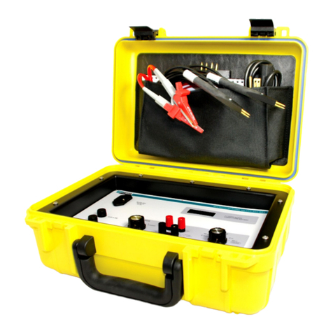
Tegam
Tegam R1L-BIR1 User manual
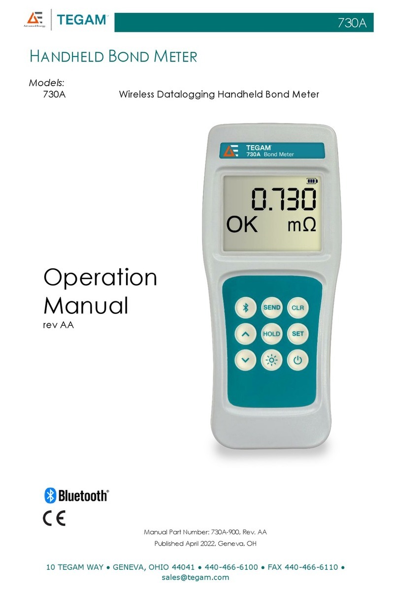
Tegam
Tegam 730A User manual
Popular Measuring Instrument manuals by other brands
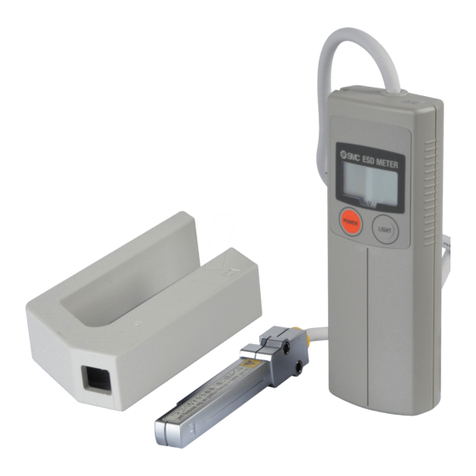
SMC Networks
SMC Networks IZH10 Series manual
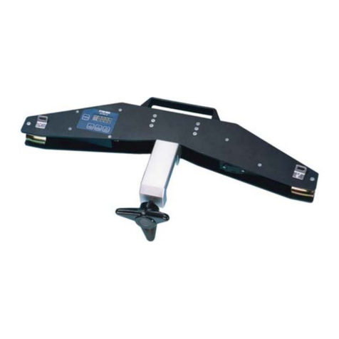
Gigasense
Gigasense RTM-D user manual
TechnipFMC
TechnipFMC Smith Meter Genesis Series Service manual

Withings
Withings Sleep Analyzer Quick installation guide

Changzhou Tonghui Electronic
Changzhou Tonghui Electronic TH2638/A Operation manual

AGFA
AGFA PCR II Plus user guide
