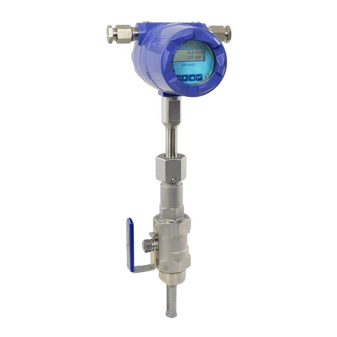
Alia AVF250 Series User manual

AVF250 Operation Manual OP250.1.1.7Z.R8ENG
1
Metal Tube Variable Area Flowmeter
Model AVF250 Series
Operation Manual
ALIA TECHNOLOGY LLC URL : http://www.alia-inc.com
TEL : +1 - 213 - 533 - 4139 FAX : +1 - 213 - 223 - 2317 OP250.1.1.7Z.R8ENG■
ALIAVA
®

AVF250 Operation Manual OP250.1.1.7Z.R8ENG
2
Index
1. Overall Check -------------------------------------------------------------------------------------------------------------------------3
2. Measuring Principle -----------------------------------------------------------------------------------------------------------------3
3. Features --------------------------------------------------------------------------------------------------------------------------------4
4. Specification---------------------------------------------------------------------------------------------------------------------------4
5. Dimensions and Pressure Loss --------------------------------------------------------------------------------------------------5
6. Installation------------------------------------------------------------------------------------------------------------------------------6
6.1 Scheme-------------------------------------------------------------------------------------------------------------------------6
6.2 Straight Pipe Requirement ------------------------------------------------------------------------------------------------7
7. Size Calculation ----------------------------------------------------------------------------------------------------------------------8
7.1 Method--------------------------------------------------------------------------------------------------------------------------8
7.2 Correction factor K-----------------------------------------------------------------------------------------------------------8
8. Installation Considerations and Maintenance------------------------------------------------------------------------------- 10
9. Wiring Diagram --------------------------------------------------------------------------------------------------------------------- 11
9.1 4-20mA Output (2-wire) -------------------------------------------------------------------------------------------------- 11
9.2 4-20mA + Pulse Output -------------------------------------------------------------------------------------------------- 11
9.3 Pulse Connection ---------------------------------------------------------------------------------------------------------- 12
9.4 Alarm-------------------------------------------------------------------------------------------------------------------------- 12
9.5 Local Indicator_ Reed Switch Alarm ---------------------------------------------------------------------------------- 13
9.6 RS485 Modbus Protocol ------------------------------------------------------------------------------------------------- 13
10. Keypad ------------------------------------------------------------------------------------------------------------------------------ 15
10.1 Display Interface----------------------------------------------------------------------------------------------------------15
11. Operational Flowchart----------------------------------------------------------------------------------------------------------- 16
12. Operation and Settings --------------------------------------------------------------------------------------------------------- 17
12.1 General Settings---------------------------------------------------------------------------------------------------------- 17
12.2 Calibration Parameter Setting----------------------------------------------------------------------------------------- 20
12.3 Other Parameter Settings ---------------------------------------------------------------------------------------------- 22
12.4 Communication Address and Size Setting------------------------------------------------------------------------- 23
13. Troubleshooting------------------------------------------------------------------------------------------------------------------- 24
Appendix Density of Common Gas and Liquid -------------------------------------------------------------------------------- 26

AVF250 Operation Manual OP250.1.1.7Z.R8ENG
3
1. Overall Check
A. Check the overwrap first. If any damages occur, please contact ALIA Customer Service Center at once.
B. Confirm whether the instrument has been damaged or its spares are lost.
C. It’s recommended that you read the manual thoroughly, once you have any quires, please email or fax to ALIA
technical department.
D. Ensure all the specifications of received instrument are in a normal state.
E. Power on to check whether the LCD screen operates normal.
F. Proper installation is required.
G. Move flowmeter and mount it into pipeline under installation instructions.
H. Connect wires and specially attention on whether they have been shielded or grounded.
I. Power on and check whether there is any current leakage (mind your own safety), then observe whether it is
displaying any flow rate. If it doesn’t, please follow steps above again, particularly on wiring, power supply and
grounding. If problem remains, please contact ALIA Technical Support center or local agent.
2. Measuring Principle
The metal tube variable area flowmeter is composed of the following two parts:
Sensor----measuring tube and float
Signal transmitter------indicator
measuring tube
pointer
steel magnet
Spindle
dial scale
float
The built-in magnet steel generates magnetic coupling from inside to outside with outside magnet steel of measuring
tube’s mechanical pole. When flow rate changes, the built-in magnet will move up and down with changes of float,
bringing in displacement of outside magnet. Then the inner shaft will be rotated and thus float’s straight displacement is
changed into shaft’s angle displacement.
With capacitor’s angle displacement, sensor’s angle change is turned into capacitor’s change. And then capacitor
value’s change is turned into voltage signals by signal processing circuit, finally showing medium’s flow rate from output
signal amplitude.
Volume Flow Rate:
f
ffA
gV
AAQ )(2
00
In formula:
0
A——Annular flow area between the float and the tube wall; Suppose the cone’s radius at float position h
is
R
, float’s max. radius is
r
and cone angle is
, then:
)2()( 2222
0
tghhrtgrRA
——Velocity
——Flow rate coefficient C
1
, C: Drag coefficient, drag from fluid on float g2
2
f
fV
CAF
g——Gravity acceleration
f
V——Float volume
f
——Float weight
f
A——Float's max. cross-sectional area
——Medium weight

AVF250 Operation Manual OP250.1.1.7Z.R8ENG
4
3. Features
5-digit flow rate&8-digit totalizer
Local indication without auxiliary power
4-20 mA and scale pulse output
Low pressure loss in gas and steam application
Damper for gas/steam application
Constant overall length
Heating jacket design, preventing fluid solidification
Intrinsically safe&explosion proof for hazardous area
4. Specification
Size (mm) : 15,20,25,40,50,65,80,100,125,150,200 Local display : Mechanical Indicator (Standard)
Measuring Range : Liquid - 1 to 200000 Liter/Hr Digit Display : 5 digit Flowrate
Gas - 0.03 to 3000 M3/Hr 8 digit Tantalizer
Steam - 6.4 to 267,000 Kg/Hr Current output : 4-20 mA (2 wire)
Turndown Ratio : 10:1 (20:1 Optional) Load : 600 Ohm
Accuracy : +/-1.6%(Standard)
Pulse output : General Pulse
+/-1.0%(Optional) Rating : 3 to 30VDC, Max:100mW
Repeatability : +/-0.5% of reading
Data Storage : Operation parameters and totalizer
Material : Stainless Steel 304 figures are stored by EEPROM for more
Stainless Steel 316 than 10 years
Stainless Steel 316L
Stainless Steel +PTFE Liner Alarm output : 2 point (Open collector)
Standard Pressure : 40 Kg/cm2 (15mm ~ 50mm) Rating : 3 to 30Vdc, 100mA Max.
16 Kg/cm2 (65mm ~ 200mm) Keyboard : 3 keys from internal for programming
Temperature :
-20 ~ +200 oC (Standard) and display control.
-25 ~ +100 oC (LCD Display) Ambient temperature : -25 to +60 oC
0 ~ +80 oC (PTFE Liner) Protection class : IP 65
-80 ~+400 oC (Optional) Intrinsically Safe, Eex ia IIC T5
Flange Type : JIS 10K / JIS 20K / JIS 40K Explosion Proof, Ex d IIB T6
ANSI 150# / ANSI 300# / ANSI 600# Housing Material : Aluminum Alloy
DIN PN 10 / PN 16 / PN25 / PN 40 Cable entry : M20 * 1.5 Option: 1/2’’NPTF
Fluid Viscosity : 15m ~ 20 mm < 30 CP Pressure Drop : 0.07 ~ 0.7 Kg/cm2
25mm ~ 125 mm <250 CP Power supply 12 ~ 32VDC (2-wire 4-20 mA)
150mm ~ 200mm < 300 CP Ni-MH Battery(3 years working hours)

AVF250 Operation Manual OP250.1.1.7Z.R8ENG
5
5. Dimensions and Pressure Loss
BT ( Bottom - Top )
Size A Weight
P
mm mm Kg mber
15 108 3.7 140
25 99 5.6 190
50 84 9.7 230
80 71 15 330
100 61 17 420
150 42 34 600
200 12 49 700
BR ( Bottom - Top Side )
Size H L A weight
P
mm mm mm mm Kg mbar
15 mm 330 250 120 7.0 180
25 mm 340 250 120 8.0 220
50 mm 560 250 120 15 280
80 mm 575 250 150 25 350
100 mm 590 250 150 29 450
150 mm 690 300 180 53 580
200 mm 780 350 200 61 700
LR / RL ( Horizontal )
Size H L weight P
mm mm mm Kg mbar
15 355 250 7.5 300
25 370 250 9 350
50 643 250 18 400
80 690 400 29 450
100 720 400 35 500
150 793 500 60 630
200 970 550 73 850
RR ( Bottom Side - Top Side )
Size H L A weight P
mm mm mm mm Kg mbar
15 380 250 120 7.2 200
25 400 250 120 8.7 280
50 643 250 120 16.6 360
80 675 250 150 28.2 450
100 700 250 150 33.5 580
150 832 300 180 58 630
200 950 350 200 68 700
Wate r
35Kg./cm235Deg.C
1000Kg/m3
AVF250
54
48
42
36
30
24
18
12
6.0
RP
60
m3 Hr/
250mm
250mm
Water
35Kg./cm235Deg.C
1000K
g
/m3
A
VF250
54
48
42
36
30
24
18
12
6.0
RP
60
m3 Hr/
170 5mm
.
H
L
A
L
A
H
Water
35Kg./cm 235Deg.C
1000Kg/m3
AVF2 50
54
48
42
36
30
24
18
12
6.0
RP
60
m3 Hr/
Water
35Kg./cm235Deg.C
1000Kg/m3
AVF250
54
48
42
36
30
24
18
12
6.0
RP
60
m3 Hr/
Water
35Kg./cm235Deg.C
1000Kg/m3
A
VF250
54
48
42
36
30
24
18
12
6.0
RP
60
m3 Hr/
Water
35Kg./cm235Deg.C
1000Kg/m3
A
VF250
54
48
42
36
30
24
18
12
6.0
RP
60
m3 Hr/
Water
35Kg./cm235Deg.C
1000Kg/m3
AVF25 0
54
48
42
36
30
24
18
12
6.0
RP
60
m3 Hr/
Water
35Kg./cm235De
g
.C
1000K
g
/m3
A
VF250
54
48
42
36
30
24
18
12
6.0
RP
60
m3 Hr/
H
H
L
H
H
Water
35Kg./cm235Deg. C
1000Kg/m3
AVF250
54
48
42
36
30
24
18
12
6.0
RP
60
m3 Hr/
Water
35Kg./cm235Deg.C
1000Kg/m3
AVF2 5 0
54
48
42
36
30
24
18
12
6.0
RP
60
m3 Hr/
L
L
L
Water
35Kg./cm235Deg.C
1000Kg/m3
AVF2 50
54
48
42
36
30
24
18
12
6.0
RP
60
m3 Hr/
Water
35Kg./cm235Deg .C
1000Kg/m3
AVF2 50
54
48
42
36
30
24
18
12
6.0
RP
60
m3 Hr/
H
L
A
L
A
H
L
A
H
Water
35Kg./cm235Deg.C
1000Kg/m3
A
VF250
54
48
42
36
30
24
18
12
6.0
RP
60
m3 Hr/
Water
35Kg./cm235Deg.C
1000Kg/m3
A
VF250
54
48
42
36
30
24
18
12
6.0
RP
60
m3H r/

AVF250 Operation Manual OP250.1.1.7Z.R8ENG
6
6. Installation
6.1 Scheme
AVF250
54
48
42
36
30
24
18
12
6.0
RP
60
m3 Hr/
AVF250
54
48
42
36
30
24
18
12
6.0
RP
60
m3 Hr/
Water
35Kg./cm235Deg . C
1000Kg/m3
AVF250
54
48
42
36
30
24
18
12
6.0
RP
60
m3 Hr/
AVF 2 5 0
54
48
42
36
30
24
18
12
6.0
RP
60
m3 Hr/
AVF2 5 0
AVF 2 5 0
→
→
→
→
→
→

AVF250 Operation Manual OP250.1.1.7Z.R8ENG
7
6.2 Straight Pipe Requirement
Proper place is vital to flowmeter installation; otherwise flowmeter’s accuracy will be influenced or even get damaged.
Water
35Kg./cm235D eg .C
1000Kg /m3
AVF 250
54
48
42
36
30
24
18
12
6.0
RP
60
m3 Hr/
Wa t e r
35Kg./cm235Deg.C
1000Kg/m3
AVF 2 5 0
54
48
42
36
30
24
18
12
6.0
RP
60
m3 Hr/
Wat er
35Kg./cm235Deg. C
1000Kg /m3
AVF250
54
48
42
36
30
24
18
12
6.0
RP
60
m3 Hr/
Horizontal
Bottom-Top
Bottom Side – Top Side Bottom - Top Side
Water
35Kg./cm235Deg.C
1000Kg/m3
AVF250
54
48
42
36
30
24
18
12
6.0
RP
60
m3 Hr/

AVF250 Operation Manual OP250.1.1.7Z.R8ENG
8
7. Size Calculation
7.1 Method
1) Qs=K×Q
Among:
Qs-flow rate of calibrated medium (water or air) under standard condition (20oC,1atm)
Q-flow rate of user’s medium
K-correction factor
2) Based on the Qs, check flow table (page 2 in datasheet) to choose float and measuring tube’s size. The flow data in
table are both under standard condition of air or water.
7.2 Correction factor K
For liquid medium:
a. If Q is volume flow rate, formula will be as below:
K
=
ρ
S
-
1ρ
(×
ρ
S
-
ρ
(
b. If Q is mass flow rate, formula will be as below:
K
=
ρ
S
-
1
ρ
(×
ρ
S
-
ρ
(
Among:
ρs: density of chosen float (g/cm3)
ρ: density of measured medium
density of stainless steel float is 7.8
density of PTFE float is 3.4
density of Hastelloy is 8.3
For air medium:
a. if Q is volume flow rate under standard condition (20 oC,0.1013Mpa), formula will be as below:
K
=
ρ
ρP
T
0
×
P
T
×
0
××
0
b. if Q is volume flow rate under operation condition, formula will be as below:
K=ρ
ρP
T
0
×
P
T
×
0
××
0
c. if Q is mass flow rate of air, formula will be:
K=ρ
ρP
T
0
×
P
T
×
0××
1 205.
1
0
Among:
ρ: the density of measured gas under condition of 20 oC and 0.1013Mpa (kg/m3)
P: the absolute pressure of measured gas (MPa)
T: the absolute temperature of measured medium (K)
ρ0: the density of air under 20℃and 0.1013Mpa (1.205kg/m3)
P0: the absolute pressure of calibrated medium (0.1013Mpa)
T0: the absolute temperature of calibrated medium (293.15K)
d. Auxiliary formula:
=ρ
P
T
P
T
×
×
t
t
t
0
0
ρ
Among:
ρ: the density of measured gas under 20 oC and 0.1013Mpa (kg/m3)
Ρt: the density of measured gas under operation condition (kg/m3)
Tt: the absolute temperature of measured gas under operation condition (K)
Pt: the absolute pressure of measured gas under operation condition (MPa)
P0: the absolute pressure of measured gas under standard condition (MPa)
T0: the absolute temperature of measured gas under standard condition (K)

AVF250 Operation Manual OP250.1.1.7Z.R8ENG
9
For steam medium:
If AVF250 is to measure saturated steam, formula will be:
=ρ
M
Q
S
29 56
.
Among:
Qs: water’s flow rate
ρ: steam’s density under operation condition (kg/m3)
M: steam’s flow rate (kg/h)
Choose flowmeter from Qs (water’s flow rate) after calculating as formula above. This formula is derived by taking float’s
density as 7900kg/m3. If float’s density changes, the factor in formula have to change as well.

AVF250 Operation Manual OP250.1.1.7Z.R8ENG
10
8. Installation Considerations and Maintenance
(1) Before installation, please sweep the process pipe first so as to avoid any magnetic particles remained inside pipe
as it will influence flowmeter’s performance or cause damage to flowmeter due to adhesion onto flowmeter. If it’s
unavoidable, please install filter before flowmeter’s inlet.
(2) The installation can be vertical and horizontal. If vertical, its centerline should not deviate more than 2°. If horizontal,
its horizontal centerline should not deviate more than 2°.
(3) The size in upstream pipe and downstream pipe should be the same with that of flowmeter, so does the connecting
flange with flowmeter’s flange. And straight pipe distance of upstream should be the 5 times of flowmeter’s size;
straight pipe distance of downstream should be more than or equal to 250mm. Please see page 7 for more details.
(4) As this flowmeter’s signal is transmitted by magnetic coupling, to ensure flowmeter’s performance, there shouldn’t
be magnetic objects around, at least 10cm away.
(5) If measuring gas in the pipe, gas should not be drained directly from flowmeter’s outlet. Otherwise there will be
pressure drop in float which in return will distort data. Thus a valve should be installed around the flowmeter’s outlet,
turning it down slowly during operation.
(6) Flowmeter that has been installed onto pipe should not be influenced by stress. There should be suitable pipe
holding at flowmeter’s inlet and outlet, making this flowmeter staying in a min. stress state.
(7) When you are installing flowmeter that has PTFE liner, please install very carefully, because PTFE will be deformed
because of pressure influence. So do not tighten the flange screws excessively.
(8) After long time’s use, if too many impurities inside pipe, the float will be jammed, or accuracy will not be certain. So
it’s necessary to clean flowmeter’s measuring tube regularly. If magnetic filter has been installed at the inlet of
flowmeter, it has to be cleaned regularly too.
(9) For first-time installation, please keep the 2 points in mind below:
Liquid measurement: when you are about to open valve, please slowly open it to avoid sudden shock damage of
water column to flowmeter if the valve is opened suddenly.
Gas measurement: do not pressurize pipe before opening the valve. If valve opened suddenly, the float will rocket to
stopper and then flowmeter will be damaged probably. So please open valve in a slow way. To measure gas, it’s
better for you to install an air damper device to minimize the shock from float.
(10) If explosion-proof flowmeter’s housing needs to be opened at site for maintenance, please turn off the power first.
(11) For the flowmeter that has liquid crystal screen, please don’t let it be exposed to the direct sunlight as it may reduce
its life.
(12) When to measure medium of low temperature, heating job should be done if heating jacket is not ordered.
(13) Before connection, please confirm power supply, output and correct terminals of power and signal in circuit board
so as to avoid damage due to wrong connection.

AVF250 Operation Manual OP250.1.1.7Z.R8ENG
11
9. Wiring Diagram
This flowmeter adopts 4-20mA output signal of 2-wire to other external equipment of device with power supply 12~36
VDC. The maximum load resistance to output circuit is 600Ω(including resistance of cable).
Generally, it’s recommended to use PVC shielded cable that resists 600V. If the environment is easily to be interfered by
noises of equipments, please use 2-core shielding cable (RWP2×0.5mm) with one of its terminals connecting to
grounding screw of flowmeter’s housing and another to the ground. Use special shielding cable that resists high/low
temperature if application temperature is too high or too low.
9.1 4-20mA Output (2-wire)
Pin 11,12 : 4-20 mA(2 Wire)
12~32VDC Power Supply
9.2 4-20mA + Pulse Output
12
72
32
11
71
31
Power
Supply
18-32VDC
4-20mA
Output
-
--
-
+
++
+
-
+
-
+
Pin 11,12 : Power Supply:18~32VDC
Pin 71,72 : 4-20mA Output
Pin 31,32 : Pulse Output
Pulse Width : 50 mS
Outer Voltage : 3~30VDC Max.:100mW
mA
12~32VDC
+
-
+
-
11
12
S
L/h
L
1211
Q 200.00
000000.00
S
Lh/
L
3132
12 11
72 71
S
Lh/
L
12 11
72 71
Q 200.00
000000.00
S
3132
Lh/
L

AVF250 Operation Manual OP250.1.1.7Z.R8ENG
12
9.3 Pulse Connection
Flow meter terminal
32-
31+
Com
In
24VDC
5Kohm
9.4 Alarm
12
72
35
11
71
34
Power
Supply
18-32VDC
4-20mA
Output
-
-
+
+
-
+
-
+
NO
COM
32
31 NO
COM
Pin 11,12 : Power Supply:18~32VDC
Pin 31,32, : H Alarm Output
Pin 34,35, : L Alarm Output
Pin 71,72 :4-20mA Output
313234
12 11
72 71
S
Lh/
L
35
12 11
72 71
Q 200.00
000000.00
S
3132 33
Lh/
L
34

AVF250 Operation Manual OP250.1.1.7Z.R8ENG
13
9.5 Local Indicator_ Reed Switch Alarm
9.6 RS485 Modbus Protocol
Baud rate, Data length, Stop bit and Parity can not be changed. They are default. User can only change Address, the
password is 5018.
32
31
33
NO
NC
COM
35
34
36
NO
NC
COM
Pin 31,32,33 :H Alarm
Pin 34,35,36 : L Alarm
Rating:1A@30VDC
Baud rate 9600
Data length 8
Stop bit 1
Parity None
Address 1~99
Communication RS485 RTU
51
71
11
52
72
12
Power
Supply
18-32VDC
4-20mA
Output
-
--
+
++
-
+
AA
BB
Pin 11,12: Power supply:18~32VDC
Pin 71,72: 4-20mA Output
Pin 51,52: RS485(Modbus Protocol)
5251 71 12 1172
Q 200.00
000000.00
S

AVF250 Operation Manual OP250.1.1.7Z.R8ENG
14
Modbus table
AVF250 Modbus Table
NO. Content Data Type Address Length Read
1 Flow Rate float Ox03E8 Ox0002 04
2 Totalizer float Ox03EA Ox0002 04
3 Current float Ox03EE Ox0002 04
4 Percentage float Ox03F1 Ox0002 04
5 Velocity float Ox03F3 Ox0002 04
6 Unit of flow rate Short 0x03EC Ox0002 03
0:L/h 1:m3/h 2:Nm3/h
3:NL/h 4:kg/h 5:t/h
6:L/min 7:m3/min
8:kg/min 9:t/min10:L/s
11:m3/s 12:kg/s 13: /s
14:/min 15:/h
7 Unit of totalizer Short 0x03ED Ox0002 03
0: L 1:m3 2: Nm3
3:NL 4:kg 5: t

AVF250 Operation Manual OP250.1.1.7Z.R8ENG
15
10. Keypad
Key Name Button Basic Function Setting Function
Enter parameter setting Save data
S S Data setting interface Increase number & Save data
Indicate data setting interface Digit shift & Decimal point shift
10.1 Display Interface
Flowrate interface
Flowrate and velocity
interface
Flowrate, percentage
and current interface
Q 000.00
m3/h
∑100
m3
Q 000.00
m3/h
∑100
m3
Q 000.00
M /s
∑100
m3
Q 000.00
m3/h
∑100
m3
Q 000.00
m3/h
∑100
m3
Q TOTRL
∑100
m3
Q 000.00%
∑100
m3
Q 4.00mA
∑100
m3
Q 000.00
M /s
∑100
m3
Q 000.00%
∑100
m3
Q 4.00mA
∑100
m3
Flowrate, velocity, percentage
and current interface
Totalizer interface

AVF250 Operation Manual OP250.1.1.7Z.R8ENG
16
11. Operational Flowchart
Q 10
m3/h
∑100
m3
02000
NO
CLR TOT
SH-d
SL-d
PULSE
PULSE q
PULSE U
BATCH U
NO
BATCHCLR
OK
POIN
TPOIN
UNITS
SSC
PRO-LO
02000
SECRET
SET
SET
SET
SET
SET
SET
SET
SET
SET
SET
SET
SET
SU-L
SET
SET
SET
SET T
NO
SET TOT
SET
PRO-Hi
SU
SU-H
SET
Q 10
m3/h
∑100
m3
SET
OK
02008
ZERO
SPAN
NO
ADCAL
DAO 4
DAF 20
SET
SET
SET
SET
SET
OK
SET
YES
ADCAL
SET
SET
AD 00
AD 10
AD 20
AD 30
AD-100
TURU
SET
SET
SET
SET
SET
SET
SET
3018
CUT OFF
DAMP
FILTER
5018
OK
SET
SET
SET
SET
SET
ID
BAUD
DN
Density
SET
SET
SET
SET SET
SET
Density

AVF250 Operation Manual OP250.1.1.7Z.R8ENG
17
12. Operation and Settings
12.1 General Settings
4-20mA output can only be set by keys.
Input Password
Press to change value and press SET to next setting.
Password: 2000
Preset Totalizer
Press to choose “YES” to preset totalizer and choose “NO” to deny.
If press SET button directly, it will skip to next setting instead of preset totalizer. .
2000
LOCK
YES
SET TOT
SET
SET
SET
SET TOT
00000000
Preset Totalizer
Preset totalizer as required.
Press to change value and press SET to next setting.
SET
NO
CLRTOT
SET
Reset Totalizer
Press to choose “YES” to reset totalizer to 0 and return to normal display.
Choose “NO” and press SET to next setting.
Parameter Setting
Press to enter parameter setting.
Press SET to skip to “SECRET” setting window.
Flow Rate Decimal Point Adjustment
0, 1, 2 and 3 are optional.
Press to change decimal point position, and press SET to next setting.
0.00
POIN
Totalizer Decimal Point Adjustment
It is limited by the decimal point of flow rate. For example, if flow rate with two decimal places,
totalizer can set up to 2 decimals.
Press to change decimal point position, and press SET to next setting.
0.0
TPOIN
SET
Unit Setting
Press to change flow unit. Options: L/h, m3/h, Nm3/h, NL/h, kg/h, t/h, L/min, m3/min, kg/min,
t/min, L/s, m3/s, kg/s. Other options: /s, /min, /h.
m3/h
UNITS
SET
SET
SSC
Q 10
m3/h
∑100
m3

AVF250 Operation Manual OP250.1.1.7Z.R8ENG
18
Alarm Output and Pulse Output Settings
Alarm High Limit Setting
Press to set the upper limit value (setting range: 0%~150%), and then press SET to next setting.
When setting value is 0, the high limit terminal is the pulse output terminal.
120
SU - H
SET
05
SH- d
Alarm High Limit Hysteresis Value
Press to change hysteresis value of alarm upper limit (setting range: 0%~30%), and then
press SET to next setting.
E.g.: Alarm point is 80, above 85 is required. Range is 100, just set 5%.
SET
The Corresponding Value of 4mA Output
Press to change value. This value corresponds to 4mA output.
Press SET to next setting.
00000
PRO-LO
The Corresponding Value of 20mA Output
Press to change value. This value corresponds to 20mA output.
Press SET to next setting.
SET
SET
Password Modification
Original Value is 2000. Do not change it unless necessary.
Press to change value and press SET to next setting.
OK
01.500
PRO-HI
Input Password
Press to change value and press SET to next setting.
Password: 2000
2000
LOCK
SET
NO
CLRTOT
Reset Totalizer
Press and choose “YES” to reset totalizer to 0 and return to normal display.
Choose “NO” and press SET to next setting.
SU
Q 10
m3/h
∑100
m3
Alarm Setting
Press to enter alarm setting.
Press SET to skip to” PULSE” setting window.
2000
SECRET
SET
Q 10
m3/h
∑100
m3

AVF250 Operation Manual OP250.1.1.7Z.R8ENG
19
Alarm Low Limit Setting
Press to set lower limit value (range: 0%~110%), and then press SET to next setting.
When setting value is 0, the low limit terminal is the pulse output terminal.
20
SU - L
Hysteresis Value of Alarm Low Limit
Press to change hysteresis value of alarm low limit (setting range: 0%~30%), and then press
SET to next setting.
E.g.: Alarm point is 20, under 15 is required. Range is 100, just set 5%.
5
SL – d
SET
Pulse Setting
Press to pulse setting.
Press SET to skip to “SSC” setting window.
PULSE
SET
05
PULSE q
SET
1.000
PULSE U
SET
Pulse Width Setting
Modify pulse width by pressing keys. It can be set to 5ms, 10ms or 50ms.
Scale Pulse Setting
Modify scale pulse by pressing keys. It can be set to 0.001, 0.01, 0.1 or 1.0. Totalizer unit
corresponds to LCD totalizer unit.
1.000
BRTCH U
Batch Pulse Setting
It’s used to batch control. Setting range: 1~50000. If choose 1that means pulse output. If it’s not 1
that means batch output. Suppose scale pulse is 1.0L/P. The number of batch pulse is 10 and the
value of batch control is 10L.
YES
BRTCHCLR
SET
Batch Clear
Press to choose “YES”, it can automatically clear batch totalizer. Choose “No” to deny.
SET
OK
Display and Output Setting
Press to decimal point setting window.
Press SET to skip to “SECRET” setting window.
SET
SSC
SET
Please see page 15 for details.

AVF250 Operation Manual OP250.1.1.7Z.R8ENG
20
12.2 Calibration Parameter Setting
Input Password
Press to change value and press SET to next setting.
Password: 2008.
2008
LOCK
SET
Flowmeter Calibration
Press to choose ”Yes” to enter flowmeter calibration, choose “NO” to skip to 4 mA calibration.
Please do not modify randomly, otherwise, instrument’s accuracy will be affected.
NO
ADCAL
SET
4740
AD 00
SET
11220
AD 10
SET
14110
AD 20
SET
16866
AD 30
SET
19620
AD 40
0% Flowrate Calibration (Please do NOT adjust this parameter randomly)
Adjust pointer to the location of RP, wait until value is stable and then press SET to next parameter.
Press to next parameter directly. Press to switch point.
10% Flowrate Calibration (Please do NOT adjust this parameter randomly)
Adjust pointer to the location of 10%, wait until value is stable and then press SET to next parameter.
Press to next parameter directly. Press to switch point.
20% Flowrate Calibration (Please do NOT adjust this parameter randomly)
Adjust pointer to the location of 20%, wait until value is stable and then press SET to next parameter.
Press to next parameter directly. Press to switch point.
30% Flowrate Calibration (Please do NOT adjust this parameter randomly)
Adjust pointer to the location of 30%, wait until value is stable and then press SET to next parameter.
Press to next parameter directly. Press to switch point.
SET
00000
ZERO
Zero Point Adjustment
Default value is 0. It’s used to calibrate lower range value. Please do not modify randomly.
Press to change value and press SET to next setting.
SET
00000
SPAN
Full Scale Adjustment
Default value is the max. value pointer stays at. It’s used to calibrate upper range value. Please do
not modify randomly.
Press to change value and press SET to next setting.
SET
40% Flowrate Calibration (Please do NOT adjust this parameter randomly)
Adjust pointer to the location of 40%, wait until value is stable and then press SET to next parameter.
Press to next parameter directly. Press to switch point.
Q 10
m3/h
∑100
m3
Table of contents
Other Alia Measuring Instrument manuals
Popular Measuring Instrument manuals by other brands

Global Test Supply
Global Test Supply DOUBLE VISION DDPM-40 quick start guide

I-Tech
I-Tech IT-E185 user manual

Digi-Sense
Digi-Sense 3622566 Operation manual

thermastor
thermastor Humiport 10 owner's manual

B+K precision
B+K precision BA8100 user manual

Powerfix Profi
Powerfix Profi PTSI 9 A1 operating instructions