Precision Rated Optics HCC-CW-201A User manual
HCC-CW-201A
CWDM Analyzer
Operation Guide

HCC-CW-201A
2 888-545-1254 | www.PrecisionRatedOptics.com
Table of Contents
Description ................................................................................................................................................................3
Features...................................................................................................................................................................3
Specifications.............................................................................................................................................................4
Safety Information....................................................................................................................................................5
Preparing for Operation...........................................................................................................................................6
Unpacking the instrument.......................................................................................................................................6
Front keys definition...............................................................................................................................................6
Rear panel definition...............................................................................................................................................7
Function Modules.................................................................................................................................................10
Description of functions........................................................................................................................................11
Menu Mode..................................................................................................................................................................12
CWDM Parameters / CWDM Parameter setting...............................................................................................12
Back light setting ..............................................................................................................................................13
Time setting......................................................................................................................................................13
OPM Parameters/OPM setting..........................................................................................................................14
View History.....................................................................................................................................................14
Auto off ............................................................................................................................................................15
Name File Name......................................................................................................................................................15
Open File ..........................................................................................................................................................15
About................................................................................................................................................................16
Warranty.................................................................................................................................................................17

HCC-CW-201A
www.PrecisionRatedOptics.com | 888-545-1254 3
Description
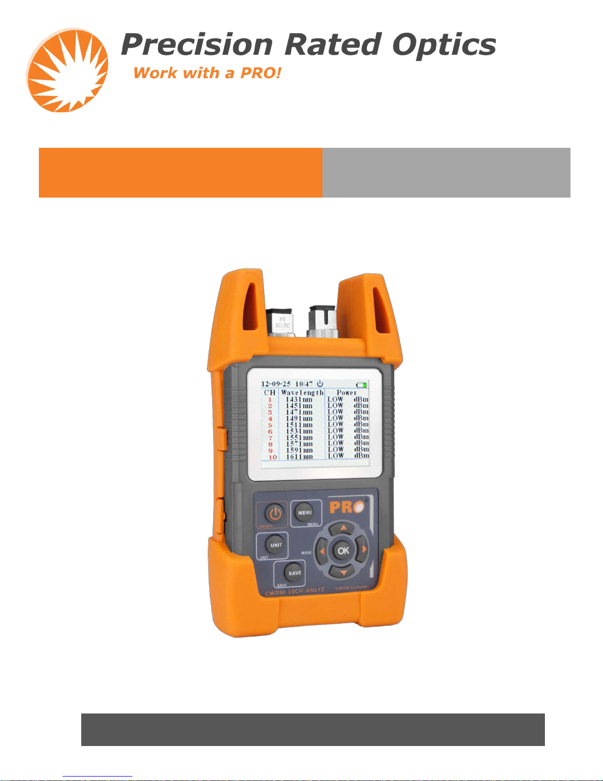
HCC-CW-201A Handheld CWDM Analyzer is specially designed for CWDM installation, maintenance and
troubleshooting, which is able to measure and monitor power values of 10 CWDM channels. HCC-CW-201A
can replace high-cost Spectrometers and conduct quick and reliable measurements in all environments. Thanks
for its light, compact and sturdy design, HCC-CW-201A is the ideal tool for CWDM installation and
maintenance technicians.
Features:
•Hand-held, more compact and easy tooperate
•TFT LCD display
•Inner timing system
•Threshold configuration: can preset threshold value
•10CH wavelength testing: 1431nm-1611nm
•Data Transfer to PC via USB
•Histogram or list data display modes
•Back light function
•Can work as the normal power meter
•10 hours continuous work data storage & download
Result display in histogram and list straight forward result display for easy understanding
Histogram mode
X axis represents the channels 1-10
from 1431nm to 1611 nm. Y axis
represents the power value (dBm).
The red value of channel number
represents cannot get through the
threshold value.
List mode
10 Channels list 3 kinds of unit:
mW / uW / dBm / dB (REF). The
red value represents failure to pass.
General Power Meter
There are six wavelengths 850nm,
1300nm, 1310nm, 1490nm,
1550nm, 1625nm.
HCC-CW-201A
4 888-545-1254 | www.PrecisionRatedOptics.com
Specifications
Wavelength (nm) 1431 ~ 1611
Power Range (dBm) -40 ~ +10
Channel Number 10
Channel Spacing 20nm
Central Wavelength ITU
Channel Band-pass ITU ±6.5nm
Channel Power Resolution ±0.01 dB
Channel Power Accuracy ±0.5 dB
Maximum Input Power 13 dBm
Return Loss >45 dB
Close Channels Insulation ≥25 dB
Non-close Channels Insulation ≥30 dB
Units of Measurement mW/uW/dB (REF)
Data Storage 1,000 Operations
Connector FC/PC (Interchangeable SC, ST)
PowerMeter
Calibrated Wavelengths (nm) 850, 1300, 1310, 1490, 1550, 1625
Power Range (dBm) -60 ~ +10
Unit mW/uW/nW/dBm/dB (REF)
Resolution ±0.25 dB (5%) @ 25 ºC
General
Power Supply NiMH Rechargeable Battery / AC Adaptor
BatteryCapacity Continuous Operation ≥10 Hours
OperatingTemperature 32ºF ~ 122ºF (0ºC ~ 50ºC)
EnvironmentalConditions 0 ~ 95% (Humidity)
Weight & Dimensions(HxWxD) 7.5” x 4” x 2” / 1.5 lbs. (191 x 102 x 51 mm / 680 g)

HCC-CW-201A
www.PrecisionRatedOptics.com | 888-545-1254 5
Safety Information
Warnings!
•Never look directly into optical outputs or a fiber while the equipment is on because invisible laser
radiation may damage your eyes.
•Do not short-circuit the terminal of AC adapter, charger or the batteries. Excessive electrical current
may cause personal injury due to fumes, electric shock or equipmentdamage.
•Connect AC power cord with the equipment and wall socket properly. While inserting the AC plug, make
sure there is no dust or dirt on the terminals and both plugs are fully seated. Incomplete engagement may
cause fuming, electric shock or equipment damage and may result in personalinjury.
•Do not operate the equipment near hot objects, in hot environments, in dusty/ humid atmosphere or when
condensation is present on the equipment. This may result in electric shock, product malfunction or poor
performance.
Discharged batteries
Remarks:
1) When the battery power is almost out, there will be a warning of indicator keeps blinking, then please
replace the batteries or plug in AC adapter to chargebatteries.
2) Please make sure that you have turned the instrument on before charge the batteries, unplug the AC
adapter when the batteries are fullycharged.
3) Please make sure the batteries are well placed before chargingthem.
4) To eliminate the possibility of acid leakage, please take out the batteries if the unit will not be used for a
long time.
AC operation
If the instrument is mainly used at one location, e.g. in a laboratory or test department, the AC adapter can be used
to power it instead of batteries. There is a DC input jack on the left side of the HCC-CW-201A instrument casing
into which the output cable of the AC adapter is plugged. And when the AC adapter is plugged in, the AC
Indicator on the LCD will be displayed.
Note:
1) Power is supplied by the AC adapter even if battery is fitted. And the battery indicator is not displayed on
the screen when AC adapter isplugged.
2) Make sure that the operating voltage of the AC Adapter/Charger is the same as the local ACline
voltage.

HCC-CW-201A
6 888-545-1254 | www.PrecisionRatedOptics.com
Preparing for Operation
Unpacking the instrument
Packing material
We suggest that you keep the original packing material. Using the original packing material is your guarantee of
protecting the instrument duringtransit.
Checking the package contents
The standard accessories of HCC-CW-201A are as follows:
•Main unit
•Quality Check Report
•Carrying Case
•User's Guide
•4*Ni-MH Batteries
Checking for damage in transit
After unpacking the instrument, check to see whether it was damaged in transit. This is particularly likely if the
outer casing is clearly damaged. If there is damage, do not attempt to operate the instrument or to repair it without
authorization. Doing so can cause further damage and you may lose your warrantyqualification.
Front keys definition
ON/OFF key ; Long press for 2-5 seconds to turn on the meter
Menu key; Testing mode , press to go into the menu; Menu mode, Press to get back to the
former menu
Units switch key ;CWDM mode , press to switch the units dBm/dB/mW ; OPM mode ,
press to switch the wavelengths
Save key; Save the important data of CWDM values
Direction selecting key
Insertion key
HCC-CW-201A
www.PrecisionRatedOptics.com | 888-545-1254 7
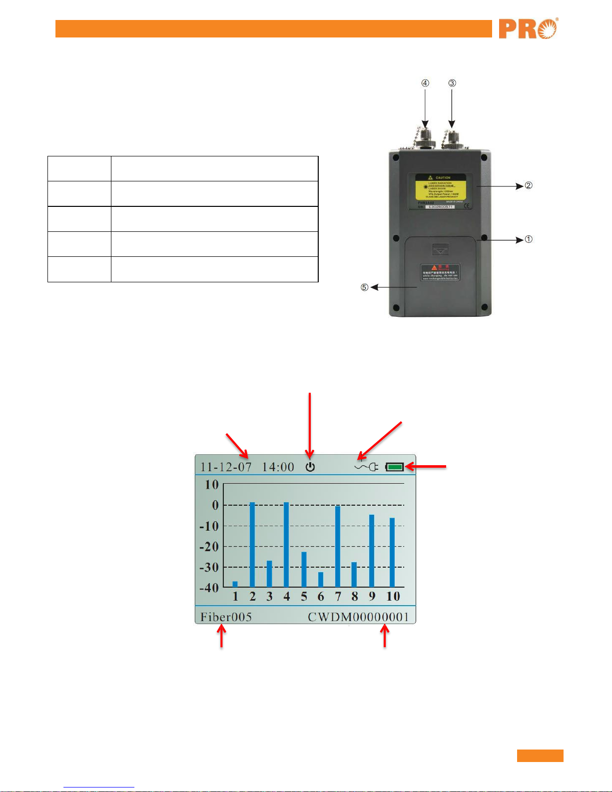
Rear panel definition
Auto power off.
You can set the function through the menu
Internal clock.
Display the real time
The series number of fiber
Adaptor connection display
The margin of battery
The name of saved data
1 9V Power adaptor interface
2 USB Interface
3 OPM Interface
4 CWDM Interface
5 Battery

HCC-CW-201A
8 888-545-1254 | www.PrecisionRatedOptics.com
Function Operation Interface
ON/OFF Press to turn on or off the meter
Power meter function
The starting interface is CWDM testing mode to
display the dBm value. Press to switch the
units: dBm/dB/mW; Press left/right key to
switch among the CWDM value list, histogram
figure, OPM power value.
Save CWDM value You can save the power value of CWDM
according to your requirement.
Menu
With testing mode, press to get into the
menu mode. Press it again back to the former
menu or testing mode.
CWDM Parameters
With menu mode, to get into the CWDM
configuration. Press to switch the
wavelength;
Press
up/down keys to set threshold value,
refer value, and rectify value; Then to save
the configuration Press to go back to the
former menu.
Back light
In menu mode, to get into the backlight
setting. Press up/down keys to adjust the
brightness of backlight. After the setting, press
to exit menu.
HCC-CW-201A
www.PrecisionRatedOptics.com | 888-545-1254 9
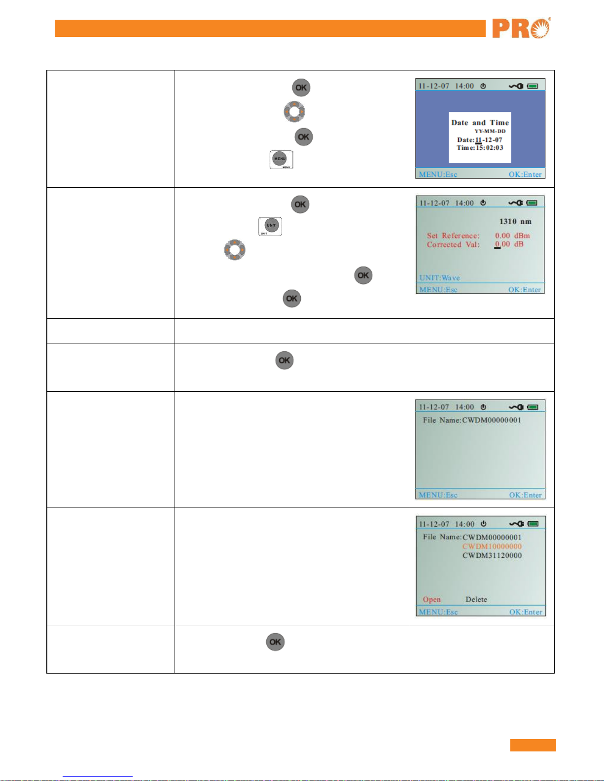
Time
In the menu mode, press to go into the time
setting mode and press to set the time. After
time setting, please press to save the
configuration, press to exit the menu.
OPM Parameters
In the menu mode, press to set the OPM
parameters. Press to change the wavelength
and press up/down key to set reference
value, rectify value. After setting, press to
save the configuration. to exit the menu.
View History Check the saved data
Auto off In menu mode, press to open or close this
function.
New File
Create a new file
Open File
Open or delete the saved file
About In the menu mode, to display the related
information
HCC-CW-201A
10 888-545-1254 | www.PrecisionRatedOptics.com
FunctionModules:
Two modes: Testing Mode and Menu Mode
The testing mode includes CWDM power meter, OPM power meter mode. Menu mode includes the following9
items.
1) CWDM Parameters
2) Back light
3) Time
4) OPM Parameters
5) View History
6) Auto off
7) New File
8) Open File
9) About
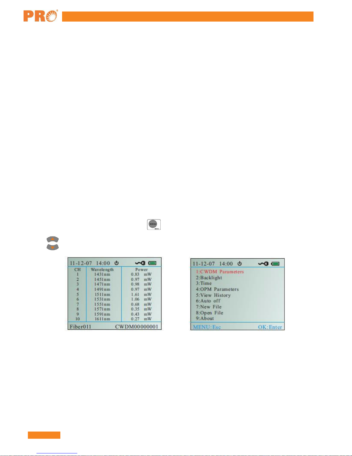
After boot-up, the meter automatically displays the testingmode.
As shown in Fig. 2, in the testing mode, press to get into the menumode.
Press
to choose the needed menu. The chosen menu is in the red color, as shown in Fig. 3.
Fig 2 Fig 3

HCC-CW-201A
www.PrecisionRatedOptics.com | 888-545-1254 11
Description offunctions
Auto power off
Auto power off function is that no operation for 10 mins, it will auto power off. In the menu mode, press to:
choose auto off mode, press to open or close this function.
CWDM power meter mode: 10 channels CWDM power display.
Press
to choose the power unit: dBm/ dB/ mW. If it displays "LOW" or "HIGH”, the value exceeds the
testing range. If the NO is red, the value is beyond the threshold value. For the detail information, you need to
check the CWDM parameter setting.
Fig 4 Fig 5 Fig 6
Save the CWDM value
You can save the CWDM values according to your requirement.
Choose the CWDM display mode: List mode / Histogram mode / General powermeter
After boot-up, it will display the CWDM power mode. Press to choose the display mode. As shown in Fig.
6, 7, 8.
Fig 6 Fig 7 Fig 8

HCC-CW-201A
12 888-545-1254 | www.PrecisionRatedOptics.com
Save the CWDM value
As it is shown in Fig. 9, in the OPM mode, Press up/down keys to choose the
needed wavelength: 850nm, 1300nm, 1310nm, 1490nm, 1550nm, 1625nm. It will
display the power of the real wavelength in dBm/ dB/mW. If it displays "LOW" or
"HIGH”, it exceeded the testing range.
Menu Mode
As is shown in Fig. 12, in the testing mode, please press to get into the menu mode. You can press to
choose the menu you need. The chosen item will display red.
CWDM Parameters / CWDM Parameter setting
CWDM parameter setting includes three items: Threshold setting, reference value setting, rectifies value setting.
Threshold setting: Compare the testing power value with the threshold values and identifies it by the display color
(Red represents failure; blue represents pass). The function make testing is so direct viewing that it can be used in
some special requirement areas. The function is suitable in some special areas. The testing range is-30dBm
+20dBm. So the minimum threshold should >-30dBm and the maximum threshold should <+20dBm (-
30<Threshold Min<Threshold Max<+20). If the "P" represents the realpower:
1) P<-30, it will display "Low" and the CH No is red.
2) -30<P<Threshold Min, it will display the power value and be in redcolor.
3) Threshold Min<P<Threshold Max, it will display the normal powervalue.
4) Threshold Max<P<+20, it will display the power value and be in redcolor.
5) P> +20, it will display" HIGH" and the CH No is red.
As it is shown in Fig. 11, the NO 1, 2, 7 power is beyond the set threshold. As it is shown in Fig.12, the NO 1, 2,
4, 6 channels is beyond the set threshold.
Fig 10 Fig 11 Fig 12
HCC-CW-201A
www.PrecisionRatedOptics.com | 888-545-1254 13
•Reference value setting: Take the dBm as the unit and it will display the real value of power; Take dB as
the unit and it will display a reference value according to the saved reference value. Reference value:
Display value=Testing value Reference value
•Rectify value setting: the original value is zero. Please set the rectify value according to your requirement.
Operation is as follows:
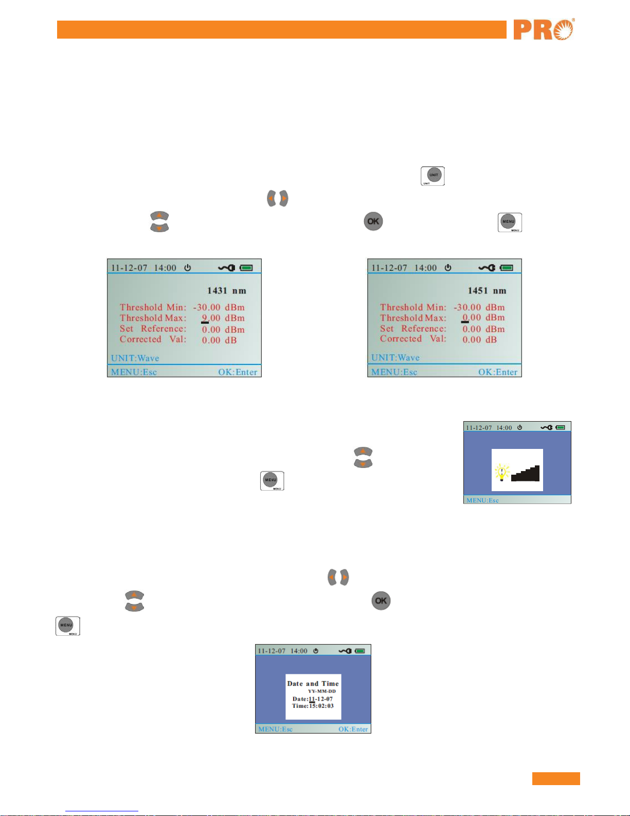
As shown in Fig.13, 14, after entering the CWDM parameter setting menu, press to switch the
wavelengths among the 10 wavelengths. Press right/left keys to move the cursor to the designated
position. Then press up/down keys to set the parameters. Press to save the setting. Press to
exit the menu.
Fig 13 Fig 14
Back light setting
Move to the back light setting menu, as is shown in Fig .15, press up/down keys
to adjust the intensity of the back light. Press to exit themenu.
Fig 15
Time setting
Get into the time setting menu, as is shown in Fig. 16. Press left/right to move cursor to the designated
position; Press up/down keys to set the time. After setting, press to save the setting. Thenpress
to exit the time setting.

HCC-CW-201A
14 888-545-1254 | www.PrecisionRatedOptics.com
Fig 16
OPM Parameters/OPM setting
Reference value setting:
Take the dBm as the unit and it will display the real value of power; Take dB as the unit and it will display a
reference value according to the saved reference value. Reference value: Display value =Testing value, Reference
value
Rectify value setting:
The original value is zero. Please set the rectify value according to your requirement. As is shown in Fig. 17, 18,
after entering the OPM setting menu , press switch the 6 wavelengths; Press left/right to move cursor to
the designated menu; Press up/down to adjust the value. After setting, press to save the current value.
Press
to exit the menu.
Fig 17 Fig 18
View History
In the "Open File" menu, choose the needed file, then get into the testing mode; to get into the menu
mode; choose View History menu it will display the latest saved power value, as is shown in Fig .19,20.
Press up key to refer the last one. Press down key to display next one. Press to back to the
View History menu.
Fig 19 Fig 20
HCC-CW-201A
www.PrecisionRatedOptics.com | 888-545-1254 15
Auto off
As is shown in Fig .21, after choosing Auto off menu, press to open/close thisfunction.
Fig 21
Name File Name
Get into the New file menu, as is shown in Fig. 22, press left/right to move cursor to the designated
position; Press up/down keys to write the file name ; Press to save the file, in the meanwhile the screen
will flash "Save File!" for one second . If you create the same name as the former file, the screen will flash "The
Saved File!" for one second. You need to rewrite the file name to save. Note: The maximum number of files is8.
Fig 22
Open File
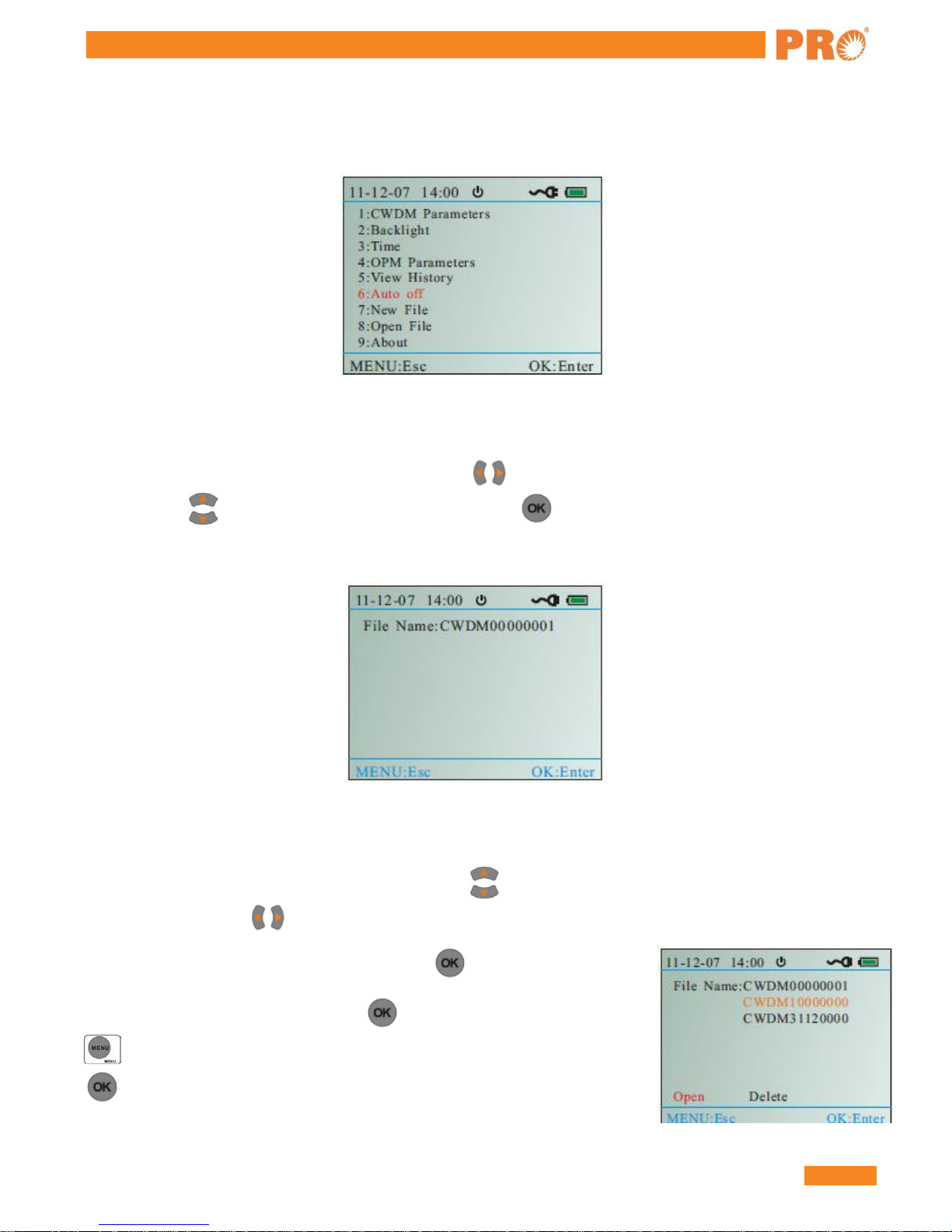
As shown in Fig. 23, get into the Open File menu; Press up/down keys to the designated file; The chosen file
is in orange color; Press left/right keys to open or delete the file; The chosen file is in blue color.
Delete file: When the Delete is in blue color, press to delete thefile.
Open file: "Open" is in blue color; Press to get into the testing mode; Press
to get into the menu mode; choose the "View History" menu ,then press
to open the chosen file.
Fig 23
HCC-CW-201A
16 888-545-1254 | www.PrecisionRatedOptics.com
Note:
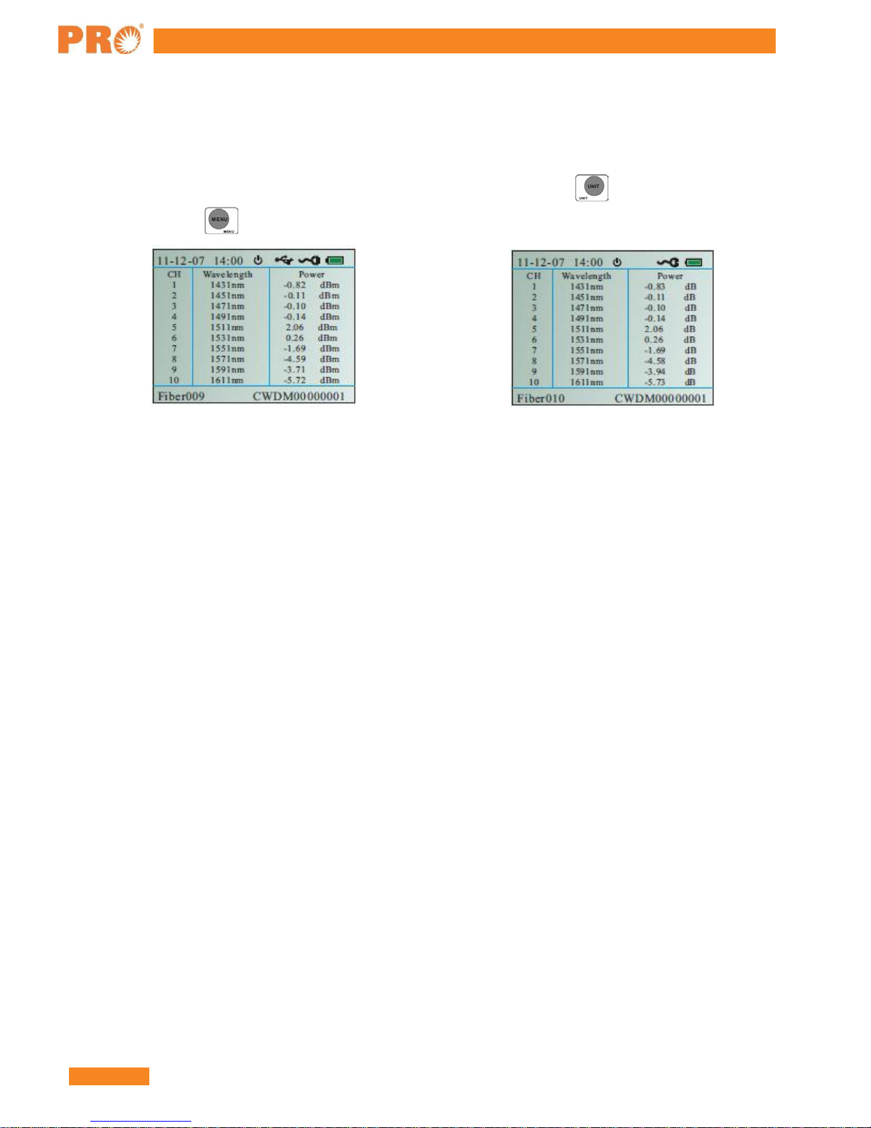
As shown in Fig. 24, 25, if you need to save a series of CWDM power value into a file. Firstly you need to
create a file or open the existing file, then in the testing mode, press to check the CWDM values
dBm/dB/mW. Press to save the value. It can save one hundred testing values.
Fig 24 Fig 25
About
After entering the About menu, press 8 to check the versioninformation.
Daily Maintenance:
1) Shut down the power in time after using the meter. Cover the fiber connector protection cap and put it in a
ventilation dry place.
2) Clean the fiber connectors regularly, keep the optical channel clean.
3) Calibrate the meter once a year to assure the testing accuracy.
4) Pick the battery out if there is a long period of no operation.
5) Don't disassemble the instrument by yourself; it could result in a permanent damage and loss of the
maintenance qualification.

HCC-CW-201A
www.PrecisionRatedOptics.com | 888-545-1254 17
Warranty
Three Years LimitedWarranty
Precision Rated Optics products are warranted against the defective components and workmanship for a period of
three years from the date of delivery to the original customer. Any product found to be defective within the
warranty period would be returned to Precision Rated Optics authorized service center for repair, replacement and
calibration.
Exclusions
The warranty on your equipment shall not apply to defects resulting from the following:
•Unauthorized repair or modification
•Misuse, negligence, or accident
Returning Product
To return product, you may contact Precision Rated Optics to obtain additional information if necessary. To serve
you better, please specify the reasons for the return. All delivery and mails should be sent to the following
address:
9999 Hamilton Blvd Breinigsville, PA 18031

Precision Rated Optics, Inc.
Corporate Office
Billing & Processing
PO Box 877 Trexlertown, PA 18087
Precision Rated Optics, Inc
.
Product Distribution Center Manufacturing & Testing
9999 Hamilton Blvd Breinigsville, PA 18031
Table of contents
Other Precision Rated Optics Measuring Instrument manuals


Popular Measuring Instrument manuals by other brands


ABB
ABB Aztec 600 user guide

PCB Piezotronics
PCB Piezotronics 340A65 Installation and operating manual

BARTEC BENKE
BARTEC BENKE HYGROPHIL F 5673 operating manual

Percul
Percul Lapcom S Separate 100 instruction manual

Campbell
Campbell CS616 Features

BPC instruments
BPC instruments Move Operation and maintenance manual


