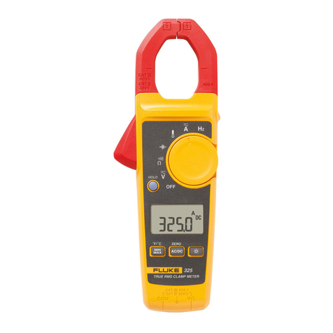
Fluke 317 User manual

2352 Walsh Ave. Santa Clara, CA 95051. U. S. A. Tel.: (408) 748-9100, Fax: (408) 748-9111 www.analogtechnologies.com
Copyrights 2000 – 2012, Analog Technologies, Inc. All Rights Reserved. Updated on 11/22/2012 1
A
nalog Technologies 317 and 319
Clamp Meter
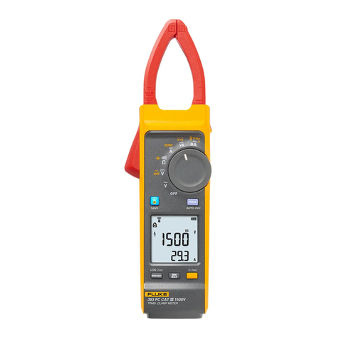
Figure 1. The Photo of Actual 317
Figure2.ThePhotoofActual319
Figure 3. The Photo of Actual 319
FEATURES
Digital Display: 6000 count resolution
Low Battery Indication: Display when the batteries are
below their required voltage
Power Source: Three AAA IEC LR03 batteries
Clamp Opening Size: 1.45"
Jaw Diameter: 1.45"
Dimension (L×W×H): 6.39"×2.29"×1.20"
Auto Range: Available in Ohms
Safety: CE
EN/IEC 61010-1 and IEC 61010-2-032
Measurement Category: 600 V CAT Ⅲ
Weight: About 384g
APPLICATIONS
It’s widely used to measure alternating voltage, direct
voltage, current, capacitance, diode, audion, resistance,
temperature, frequency, etc.
DESCRIPTION
The 317 and 319 are hand-held and battery-operated clamp
meters that can measure AC current, DC current, AC voltage,
DC voltage, resistance, continuity and frequency.
The clamp meter is battery powered with a digital display.
Except where noted, the descriptions and instructions in this
datasheet apply to both the 317 and 319 clamp meters.
Warning: To avoid possible electric shock or
personal injury, read “Safety Information” before using
the clamp meter.
SAFETY INFORMATION
Use the clamp meter only as specified in this datasheet,
otherwise the protection provided by the clamp meter may be
impaired.
Adhere to local and national safety codes. Individual
protective equipment must be used to prevent shock and arc
blast injury where hazardous live conductors are exposed.
Use extreme caution when working around bare conductors
or bus bars. Contact with the conductor could result in
electric shock.
Use caution when working with voltages above 30V AC rms,
42V AC peak, or 60V DC. These voltages pose a shock
hazard.
Never measure current while the test leads are inserted into
the input jacks.
Do not use the clamp meter in wet, dirty or hazardous

2352 Walsh Ave. Santa Clara, CA 95051. U. S. A. Tel.: (408) 748-9100, Fax: (408) 748-9111 www.analogtechnologies.com
Copyrights 2000 – 2012, Analog Technologies, Inc. All Rights Reserved. Updated on 11/22/2012 2
A
nalog Technologies 317 and 319
Clamp Meter
environment.
Do not use the clamp meter or test leads if either appears
damaged. Inspect the clamp meter and test leads before
using. Look for cracks or missing plastic. Pay attention to
the insulation around the connectors. Do not use if
insulation is damaged or metal is exposed.
Check the test leads for continuity. Do not use the clamp
meter if test leads read open.
When using probes, keep fingers behind the finger guards.
Do not hold the clamp meter anywhere above the tactile
barrier. See figure 5.
Disconnect circuit power and discharge all high-voltage
capacitors before testing resistance, continuity, or diodes.
Check clamp meter operation on a known source before
and after use.
Use the proper terminals, function, and range for your
measurements.
Do not apply more than the rated voltage, as marked on
clamp meter, between any terminal and earth ground.
Before opening back cover to replace batteries, remove test
leads and disconnect clamp meter from any circuits being
measured. Do not operate clamp meter with cover removed
or the case open.
To avoid false readings that can lead to electrical shock or
injury, replace the batteries as soon as the low-battery
indicator ( ) appears. The clamp meter will shut down
when the batteries get low.
Have the clamp meter serviced only by qualified service
personnel.
Do not use the current sensor if the wear indicator in the
jaw opening is not visible. See figure 4.
Figure 4. Jaw Wear Indicators
Table 1. Symbols
Risk of danger. Important information. Refer to operation instructions.
Hazardous voltage. Risk of electric shock.
Application and removal from hazardous live conductors permitted.
Double insulated
Battery
Earth ground
~Volts AC
Jaw wear Indicator

2352 Walsh Ave. Santa Clara, CA 95051. U. S. A. Tel.: (408) 748-9100, Fax: (408) 748-9111 www.analogtechnologies.com
Copyrights 2000 – 2012, Analog Technologies, Inc. All Rights Reserved. Updated on 11/22/2012 3
A
nalog Technologies 317 and 319
Clamp Meter
Volts DC
Conforms to applicable European directives.
CAT ⅢFor measurements performed in the building installations such as distribution panels, feeders
and short branch circuits and lighting systems in large buildings.
Do not dispose of this product as unsorted municipal waste.
GENERAL SPECIFICATIONS
Table 2. Electrical Specifications
The accuracy specification is defined as ± (% reading+digits) at 23 ±℃5℃.
Function Parameter 317 319
(A ac)
Range 40.00A
600.0A
40.00A
600.0A
1000A
Resolution 0.01A
0.1A
0.01A
0.1A
1A
Accuracy
1.6%±6digit
(50-60Hz)
[40A]
2.5±8digit
(60-500Hz)
[40A]
1.5%±5digit
(50-60Hz)
[600A]
2.5±5digit
(60-500Hz)
[600A]
1.6%±6digit
(50-60Hz)
[40A]
2.5±8digit
(60-500Hz)
[40A]
1.5%±5digit
(50-60Hz)
[600A/1000A]
2.5±5digit
(60-500Hz)
[600A/1000A]
Crest factor add 2% into
spec for CF>2
3.0Max@500A
2.5Max@600A
3.0Max@500A
2.5Max@600A
1.4Max@1000A
AC response rms rms
( A dc)
Range 40.00A
600.0A
40.00A
600.0A
1000A
Resolution 0.01A
0.1A
0.01A
0.1A
1A
Accuracy
1.6%±6digit
[40A]
1.5%±5digit
[600A]
1.6%±6digit
[40A]
1.5%±5digit
[600A/1000A]
Range 600.0V

2352 Walsh Ave. Santa Clara, CA 95051. U. S. A. Tel.: (408) 748-9100, Fax: (408) 748-9111 www.analogtechnologies.com
Copyrights 2000 – 2012, Analog Technologies, Inc. All Rights Reserved. Updated on 11/22/2012 4
A
nalog Technologies 317 and 319
Clamp Meter
(V ac) Resolution 0.1V
Accuracy 1.5%±5 digit (20-500Hz)
AC response rms
(V dc)
Range 600.0V
Resolution 0.1V
Accuracy 1%±4 digit
Ω
Range 400.0Ω
4000Ω
Resolution 0.1Ω
1Ω
Accuracy 1%±5 digit
≤30Ω
Inrush Integration time N/A 100ms
Hz
Range N/A 5.0-500.0Hz
Accuracy N/A 0.5%±5 digit
Trigger Level N/A
10-100Hz ≥5
A, 5-10Hz,
100-500Hz ≥10A
The accuracy specifications apply at 73℉±41℉ (23℃±5 )℃
Below 64 and above 82 (18 and above 28 ) accuracy degrades at (0.1) times specification per .℉℉℃℃ ℃
True rms for ac V and ac A accuracy is specified from 5% to 100% of range.
Table 3. Environmental Specifications
Operating Temperature 14℉to 122℉(-10 to 50℃℃)
Storage Temperature -40℉to 140℉(-40℃to 60℃)
Operating Humidity
Non condensing (<50℉) (<10℃)
90% RH (50℉to 86℉) (10℃to 30℃)
75% RH (86℉to 104℉) (30℃to 40℃)
45% RH (104℉to 122℉) (40℃to 50℃)
Without Condensation
Operating Altitude 1 mile (2000 meters) above mean sea level
Storage Altitude 7 miles (12,000 meters ) above mean sea level
IP Rating IP40
Vibration Requirements Random MIL-PRF-28800F Class 2, 5-500HZ, 30
minutes per axis
Drop Test Requirements 3 ft (1m) drop test, six sides, oak floor
EMI, RFI, EMC Instrument unspecified for use in EMC field ≥0.1V/m

2352 Walsh Ave. Santa Clara, CA 95051. U. S. A. Tel.: (408) 748-9100, Fax: (408) 748-9111 www.analogtechnologies.com
Copyrights 2000 – 2012, Analog Technologies, Inc. All Rights Reserved. Updated on 11/22/2012 5
A
nalog Technologies 317 and 319
Clamp Meter
Temperature Coefficients
0.1× (specified accuracy)/℃
(<64℉or >82℉)
(<18℃or >28℃)
METER FUNCTION
Table 4.
○
1Current sensing clamp
○
2
Tactile barrier
Warning: To avoid injury, do not hold the clamp meter anywhere above
the tactile barrier.
○
3 Rotary function switch
○
4 Select AC or DC
○
5 Hold button: freeze the display reading and releases the reading when pressed a
second time.
○
6 LCD
○
7
Min Max button: when first pressed, the clamp meter shows maximum input. With
subsequent presses, the minimum and the average inputs are shown. Hold for 2
seconds to exit min max mode.
This function works in current, voltage and Hz modes.
○
8 Inrush button (319 only): press this button to enter inrush mode. Press it a second time
to exit. Integration time is 100ms.
○
9 Volts/Ohm input terminal
○
10 Common terminal
○
11 Zero button: zero the display for DC measurement.
○
12 Backlight button: turn the backlight on and off. The Blacklight stays on for 2 minutes
when there is no button or switch interaction and then shuts off.

2352 Walsh Ave. Santa Clara, CA 95051. U. S. A. Tel.: (408) 748-9100, Fax: (408) 748-9111 www.analogtechnologies.com
Copyrights 2000 – 2012, Analog Technologies, Inc. All Rights Reserved. Updated on 11/22/2012 6
A
nalog Technologies 317 and 319
Clamp Meter
○
13 Jaw release
○
14 Alignment marks: to meet accuracy specifications the conductor must be aligned with
the marks.
Table 5. Rotary Switch
Switch Position Function
OFF Clamp meter is powered down
DC and AC voltage
Resistance and continuity
40A current range
600A current range
1000A current range (319 only)
Hz Frequency (319 only)
Table 6. Display
To see all segments on the display at once, press while turning the clamp meter on.
○
1 Inrush is active (319 only) ○
7DC mode
○
2 Hold is active ○
8AC mode
○
3 Volts ○
9Batteries are low and must be changed
○
4 Amps ○
10 Negative reading
○
5 Ohms ○
11 High voltage indicator
○
6 Hertz (319 only) ○
12
MAX-Maximum reading displayed
MIN-Minimum reading displayed
AVG-Average reading is displayed
TAKING MEASUREMENTS
Warning
To avoid electric shock or personal injury:

2352 Walsh Ave. Santa Clara, CA 95051. U. S. A. Tel.: (408) 748-9100, Fax: (408) 748-9111 www.analogtechnologies.com
Copyrights 2000 – 2012, Analog Technologies, Inc. All Rights Reserved. Updated on 11/22/2012 7
A
nalog Technologies 317 and 319
Clamp Meter
When making current measurements, disconnect the test leads from the clamp meter.
Keep fingers behind Tactile Barrier. See table 4.
Note
When measuring current, center the conductor in the clamp using the alignment marks on the clamp. See table 4.
Zero
Before taking DC measurements, zero the clamp meter to ensure correct readings. Zeroing the clamp meter removes DC offset
(ambient noise) from the reading.
Note
Before zeroing the clamp meter, make sure the jaws are closed and there is no conductor between them.
To zero the clamp meter, press .
MEASURING AC OR DC CURRENT
To measure AC or DC current:
1. Turn the rotary function switch to the proper current range.
2. Press to select DC current if necessary. The default is AC current.
3. If measuring DC, wait for the display to stabilize and then press to zero the clamp meter.
Note: Before zeroing the clamp meter, make sure the jaws are closed and there is no conductor between them.
4. Open the clamp by pressing the jaw release and insert the conductor to be measured into the clamp.
5. Close the clamp and center the conductor using the jaw alignment marks.
6. View the reading on the LCD.
Warning: To avoid possible electric shock or personal injury, currents moving in opposite directions cancel each
other. Place only ONE conductor into the clamp at a time, see figure 5.
Figure 5. Connecting the Clamp Meter
MEASURING AC AND DC VOLTAGE
Warning
To avoid electric shock or personal injury:

2352 Walsh Ave. Santa Clara, CA 95051. U. S. A. Tel.: (408) 748-9100, Fax: (408) 748-9111 www.analogtechnologies.com
Copyrights 2000 – 2012, Analog Technologies, Inc. All Rights Reserved. Updated on 11/22/2012 8
A
nalog Technologies 317 and 319
Clamp Meter
When making electrical connectors, connect the common test lead before connecting the live test lead; when
disconnecting, disconnect the live test lead before disconnecting the common test lead.
When using test probes, keep fingers behind the finger guards.
To measure AC or DC voltage:
1. Turn the rotary function switch to .
2. If measuring DC voltage, press to shift to DC voltage. The default is AC voltage.
3. Connect the black test lead to the COM terminal and the red test lead to the terminal.
4. Measure the voltage by touching the probes to the desired test points of circuit. See figure 6 and 7.
5. See the reading on the LCD.
Figure6.ACVoltageMeasurement Figure7.DCVoltageMeasurement
MEASURING RESISTANCE
Warning
To avoid possible electric shock or personal injury, when measuring resistance in a circuit, make sure the power to the
circuit is turned off and all capacitors are discharged.
To measure resistance:
1. Turn the rotary function switch to .
2. Remove power from the circuit being tested.
3. Connect the black test lead to the COM terminal and the red test lead to the terminal.
4. Measure the resistance by touching the probes to the desired test points of the circuit. See figure 8.
5. See the reading on the LCD.

2352 Walsh Ave. Santa Clara, CA 95051. U. S. A. Tel.: (408) 748-9100, Fax: (408) 748-9111 www.analogtechnologies.com
Copyrights 2000 – 2012, Analog Technologies, Inc. All Rights Reserved. Updated on 11/22/2012 9
A
nalog Technologies 317 and 319
Clamp Meter
Figure8.MeasuringResistance
TESTING CONTINUITY
Warning
To avoid electrical shock when testing continuity in a circuit, make sure the power to the circuit is turned off and all capacitors
are discharged.
To test continuity:
1. Remove power from the circuit being tested.
2. Turn the rotary function switch to .
3. Connect the black test lead to the COM terminal and the red test lead to the terminal.
4. Connect the probes across the circuit or component to be tested. See figure 9.
5. If the resistance is <30Ω, the beeper sounds continuously denoting continuity. If the display reads OL, the circuit is open.
Figure9.MeasuringContinuity
Warning
To avoid electrical shock or personal injury, do not touch the terminals while measuring. Dangerous voltages can be
present at the input terminals but not displayed.

2352 Walsh Ave. Santa Clara, CA 95051. U. S. A. Tel.: (408) 748-9100, Fax: (408) 748-9111 www.analogtechnologies.com
Copyrights 2000 – 2012, Analog Technologies, Inc. All Rights Reserved. Updated on 11/22/2012 10
A
nalog Technologies 317 and 319
Clamp Meter
MEASURING CURRENT FREQUENCY (319 ONLY)
To measure current frequency:
1. Turn the rotary switch to Hz.
2. Open the clamp by pressing the jaw release and insert the conductor to be measured into the clamp.
3. Close the clamp and center the conductor using the jaw alignment marks.
4. See the reading on the LCD.
The frequency reading appears on the display.
HOLD
To capture and hold the present reading, press while taking a reading. Press again to return to the live reading. High
voltage will be designated by .
MIN MAX AVG
To use the Min Max Avg functions:
1. Press once to set the clamp meter to MAX (maximum) mode.
2. Press again to set the clamp meter to MIN (minimum) mode.
3. Press a third time and the clamp meter displays an AVG (average) of the readings.
4. Pressing for more than 2 seconds sets the clamp meter back to normal operation.
5. Press in MIN MAX AVG mode to freeze the realtime record. In this mode, press to select a recorded value to view.
INRUSH CURRENT (319 ONLY)
To measure inrush current (see figure 10.)
1. Place the source wire into the clamp. Make sure the wire is below the alignment marks on the clamp.
2. With the source power off, turn the clamp meter to the correct range of .
3. Press .
4. Switch the source power on and note the inrush current reading on the display.
Figure10.MeasuringInrushCurrent
Off On

2352 Walsh Ave. Santa Clara, CA 95051. U. S. A. Tel.: (408) 748-9100, Fax: (408) 748-9111 www.analogtechnologies.com
Copyrights 2000 – 2012, Analog Technologies, Inc. All Rights Reserved. Updated on 11/22/2012 11
A
nalog Technologies 317 and 319
Clamp Meter
AUTO POWER OFF
The clamp meter turns of if there is no button pushed or rotary function switch operation for 20 minutes. Turn the clamp meter
off and on to restart the clamp meter. This feature is disabled in MIN, MAX and HOLD modes; it can also be disabled for all
modes by holding while turning the clamp meter on.
MAINTENANCE
Warning
To avoid electrical shock, or personal injury:
Repairs or servicing not covered in this datasheet should be performed only by qualified personnel.
Disconnect test leads from the clamp meter before removing its back cover.
Never use the clamp meter with back cover removed.
Caution
If the clamp meter is not going to be used for an extended time, remove the batteries. Do not store the clamp meter in
high temperature or high humidity environments.
CHANGING BATTERIES
When battery voltage drops below the value required for proper operation, the battery symbol ( ) appears. Although the clamp
meter continues to work correctly, the batteries should be replaced as soon as possible. As the battery voltage drops below the
low limit, the clamp meter will shut down.
To change batteries:
1. Turn the clamp meter off and disconnect the test leads.
2. Using a screwdriver, open the battery cover on the bottom of the clamp meter.
3. Replace the batteries with three new AAA IEC LR03 batteries.
4. Close the back cover and tighten the screw.
CLEANING THE CLAMP METER
Caution
To avoid damaging the clamp meter, do not use abrasives or solvents on this instrument.
Periodically clean the clamp meter by wiping it with a damp cloth, mild soap may be used.
ORDERING INFORMATION
Table 7. Unit Price
Part# UnitPrice
317 $166.07
319 $211.19
NOTICE
1. ATI reserves the right to make changes to its products or to discontinue any product or service without notice, and advise
customers to obtain the latest version of relevant information to verify, before placing orders, that information being relied on is
current and complete.
2. All products are sold subject to the terms and conditions of sale supplied at the time of order acknowledgment, including
those pertaining to warranty, patent infringement, and limitation of liability. Testing and other quality control techniques are
utilized to the extent ATI deems necessary to support this warranty. Specific testing of all parameters of each device is not
necessarily performed, except those mandated by government requirements.

2352 Walsh Ave. Santa Clara, CA 95051. U. S. A. Tel.: (408) 748-9100, Fax: (408) 748-9111 www.analogtechnologies.com
Copyrights 2000 – 2012, Analog Technologies, Inc. All Rights Reserved. Updated on 11/22/2012 12
A
nalog Technologies 317 and 319
Clamp Meter
3. Customers are responsible for their applications using ATI components. In order to minimize risks associated with the
customers’ applications, adequate design and operating safeguards must be provided by the customers to minimize inherent or
procedural hazards. ATI assumes no liability for applications assistance or customer product design.
4. ATI does not warrant or represent that any license, either express or implied, is granted under any patent right, copyright,
mask work right, or other intellectual property right of ATI covering or relating to any combination, machine, or process in
which such products or services might be or are used. ATI’s publication of information regarding any third party’s products or
services does not constitute ATI’s approval, warranty or endorsement thereof.
5. IP (Intellectual Property) Ownership: ATI retains the ownership of full rights for special technologies and/or techniques
embedded in its products, the designs for mechanics, optics, plus all modifications, improvements, and inventions made by ATI
for its products and/or projects.
Other manuals for 317
2
This manual suits for next models
1
Table of contents
Other Fluke Measuring Instrument manuals

Fluke
Fluke 78 User manual

Fluke
Fluke Victoreen 451P User manual

Fluke
Fluke RUSKA 2465A-754 User manual

Fluke
Fluke 433 User manual

Fluke
Fluke 772 User manual

Fluke
Fluke BT520 Configuration guide

Fluke
Fluke 700GA4 User manual

Fluke
Fluke ScopeMeter 124B User manual

Fluke
Fluke 80K-40 User manual

Fluke
Fluke 85RF User manual

Fluke
Fluke 726 Configuration guide

Fluke
Fluke 323 User manual

Fluke
Fluke 405 Original instructions

Fluke
Fluke 35040 Operators User manual

Fluke
Fluke 712B User manual

Fluke
Fluke a3001 FC User manual

Fluke
Fluke 732C Configuration guide

Fluke
Fluke i30s User manual

Fluke
Fluke PRO3000 User manual

Fluke
Fluke OC3port Plus User manual