Precision Toy Train Tools PTTTUSA Manual

INTRODUCTION
PTTTUSA
The Adjustable Rivet & Wheel Press
System
Setup Instructions
PTTTUSA
Division of Precision Metal Crafters
220 Huff Avenue

2
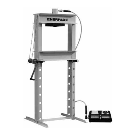
The Precision Toy Train Tools USA (PTTTUSA) STX-360 Adjustable Rivet and Wheel
Press system is a unique, accurate, heavy-duty tool system developed for the repair of
toy trains. Precise alignment of tooling components is made quickly and simply with the
PTTTUSA exclusive adjustable base plate design and accompanying alignment tool.
The PTTTUSA press and tooling system will enable you to perform factory-like results in
your home workshop or your service station.
In addition to the best press available, our tooling system includes high quality rivet
clinchers, punches, rivet anvils, axle insertion tools, wheel cups and specialty tools.
This booklet has been prepared to provide you with an overview of how to set up the
press and use its basic features. Greater detail can be found in our user manual.
SETUP & GENERAL USE INSTRUCTIONS
Please read this information completely before attempting to setup and use your
STX press!
UNPACKING THE PRESS
Your STX press system has been partially disassembled for ease in shipping. Carefully
unpack and identify all of the components using the reference at Figure 1.
1. Press assembly with base plate
2. Lever arm and pinion gear assembly with arm locking knob
3. Retaining collar for lever arm and appropriate hex key
4. Hex Key for Base Plate Socket Head Cap Screws
5. STX-360-37 Tapered Setup Tool with Protective Cap
6. STX-360-38 Solid Plate Plug for flat working surface
7. STX-360-34 Threaded Anvil holder with Two Lock Nuts
8. Thumb Screws Installed in Base Plate and Ram
9. 2 Set Screws with Hex Key
Not Shown: Two Delrin slide strips installed inside press head as shipped.
Setup Instruction Booklet.
**If any of the above components are damaged or missing, please contact us
immediately. In the event of damage, inspect the shipping carton for abuse and notify
the carrier. Keep all shipping material.

3
Figure 1 –Press System Unpacked
1
7
6
5
4
3
2
8
9
Base
Plate +
Screws
Ram
Remove Paper
Packing

4
SETUP LOCATION
Assembly of your STX SYSTEM is quick and simple. The press is heavy and therefore it
must be mounted on a sturdy surface.
NOTE: Failure to properly mount this press to your work surface can result in injury to you should
the press tip over. Ensure the area is well lit for your safety.
ASSEMBLY OF PRESS PARTS
First, make sure that the ram of the press is in its full down position. Next, insert the
geared pinion (Item #2 in Figure 1) through the head of the press. Take care to ensure
that the teeth of the geared pinion of the lever arm properly engages the teeth of the
ram. As you insert the geared pinion, take note of where the lever arm is located and
remove and reinsert the pinion gear to place the lever arm most comfortable to you.
Once the geared pinion and its associated lever arm is where you would like it to be,
install the collar (Item #3 in Figure 1) on the end of the pinion shaft and tighten the set
screw with the hex key provided. Leave a very slight bit of play when you position the
collar to prevent binding as the handle is rotated to move the ram. See Figure 2 below.
Note: You may use a small amount of light weight oil or grease on the gears of the ram drive and pinion if
the teeth are dry prior to assembly.
Figure 2
Adjustment
Bolts
Side Adjustment
Bolts
Collar and Set Screw

5
RAM ADJUSTMENTS
Prior to shipping your press, it received an initial adjustment to remove any slack in the
assembly. Test the feel of the ram by moving the lever arm and ensure that the
movement is firm but smooth prior to use.
Note: A ram that feels loose will not consistently return to its center position. Too tight is
unnecessary and causes premature wear.
Normal adjustments become necessary from time to time as parts wear in or after
heavy use. Our press can be reset to its zero position at any time you feel it necessary
using the following instructions.
The ram head guide of the press is where the ram slides up and down through the
press body. To adjust all of the play or "wobble" out of this action, there are two
adjustment bolts on the front and two adjustment bolts on the left side of the ram head.
The two front adjustment bolts cause a Delrin strip to press against the front of the ram
to tighten the feel of the lever arm. The side adjustment bolts remove side-to-side slack.
See Figure 2
Here’s the procedure:
Locate the front and side adjustment bolts. Loosen all of the lock nuts enough so that
the adjustment bolts move freely, then gently turn the adjusting bolts counter clockwise
to loosen them slightly.
Next, turn the front adjustment bolts clockwise evenly until you feel a slight binding of
the up and down travel of the ram. Now back out both of those adjustment bolts one
sixteenth to an eighth of a turn and then tighten the lock nut.
Next, turn the side adjustment bolts clockwise evenly to remove any remaining slack in
the travel of the ram following the same process as you used with the front adjustment
bolts. Remember to retighten lock nuts to secure the adjustment. The ram travel should
now be snug and smooth but not overly tight.
NOTES:
1. The adjustment bolts shipped with the press casting have metric threads.
2. Delrin Slide Strips:Installed inside the ram head guide are two Delrin slide
strips. These strips create a low friction surface between the ends of the
adjustment bolts and the ram face to avoid metal to metal contact. Over-
tightening the screws will cause premature wear of these strips. Adjustment bolts
that are too loose may allow the strips to slip out of position. Should these strips
wear over time, they are easily replaceable.

6
THE THREADED ANVIL HOLDER
The STX-360-34 threaded anvil holder is a versatile tool holder. One end holds 3/8”
diameter tools, while the other end is designed for larger diameter tools such as double
ended tools and larger anvils. There is a through hole that axles can pass through for
wheel work. The height is adjusted by positioning the lock nuts. More details about the
use of this threaded anvil holder appear throughout this manual.
3/8” socket 3/8” shank tool in the Counter-bored socket for Double-ended tool in
socket double ended and larger place on mounted
shank tools anvil holder
BASE PLATE AND TOOL ALIGNMENT - - - The Key to Accuracy
Ours is the only completely adjustable press available today. By creating an adjustable
base plate we are able to remove any misalignment between the ram center line and
the center line of the hole in the base plate. This ensures that any tool inserted in the
ram is centered on any anvil tool placed in the base plate. Properly aligned tools
improve the quality of the work performed. Our adjustable base plate (See Figure 3a
below), in conjunction with the tapered alignment tool, make alignment quick and easy.
Among the items included with your press is a special tapered alignment tool with a
protective cap. (See Figure 3b below) It is used to align the ram to the base plate. It is a
precision tool designed for alignment purposes only. The point is sharp and delicate –
so be careful. This fine point is also used as a visual center indicator when preparing a
setup as explained later in this manual. Always store this tool with its protective cap in
place to prevent damage. Use care when handling and storing this tool.
Note: The alignment tool is never to be used as a punch or pressing tool.
Figure 3a: STX-360-35 Adjustable Base Figure 3b STX-360-37 Alignment Tool and Cap

7
METHODS OF ALIGNMENT
Ram to Base Plate Alignment
First we will explore the basic base plate alignment. Looking at the base plate as it is
installed in the base of the press; you will note that there are 2 cap screws, 1 in each of
the two front corners. Unloosen these cap screws just enough so that the plate can
move freely around these screws. See Figures 4 below.
Figure 4 –Loosened Plate –Note the range of Figure 5 –Alignment Tool inserted into the Ram
movement possible around the head of the
cap screw.
Figure 6 –Lowering the Alignment Tool into Figure 7 –Base Plate centered and secured
the hole in the base plate.
Place the tapered alignment tool into the ram until seated and tighten the thumbscrew to
hold it in place. See Figure 5. Now lower the ram so that alignment tool engages the
hole in the base plate with light pressure causing the base plate to center around the

8
alignment tool. See Figure 6. The tapered tip automatically centers the plate for you.
While maintaining light pressure on the ram holding the base plate in place, turn the cap
screws clockwise to tighten them using the included hex key. See Figure 7. The plate
screws only need to be tightened enough to prevent lateral (side-to-side) movement.
Over-tightening these cap screws is not necessary.
Ram to Threaded Anvil Holder Alignment
There will be times when you will need the extended length of the threaded anvil holder,
and with it, need to accurately align the center of the anvil holder to the centerline of the
ram. Take the threaded anvil holder with one of its two lock nuts removed and insert it
into the hole in the base plate with the end you wish to use facing upwards. Add the
bottom lock nut and adjust both lock nuts to set the height of the anvil holder to the
height you need and then tighten the top lock nut. See Figure 8 below.
Figure 8 –Threaded anvil secured to base plate Figure 9 –Aligned anvil assembly
Loosen the 2 cap screws in the base plate. Place the tapered alignment tool into the
ram until seated and tighten the thumbscrew to hold it in place. Now lower the ram so
that alignment tool engages the hole in the threaded anvil holder with light pressure
causing the base plate with the anvil holder to center around the alignment tool. Once
center is established, and while maintaining pressure on the ram to hold the base plate
centered, tighten the two cap screws to secure the position of the base plate.
See Figure 9
This process enables you to center the tip of any tool used in the ram to the center of
the anvil using the extended length of the threaded anvil holder. Any tolerance slack
between the hole in the base plate and the outside diameter of the threaded anvil holder
has been removed.

9
Ram to Fixed Height Anvil Holder Alignment
A fixed height anvil holder STX-360-39 shown immediately below is included with the
STX-360-80, 11 piece Anvil Set. Additionally, the STX-360-40 fixed height clincher anvil
(not shown) will use the same alignment procedure.
To align this anvil holder, place it into the base plate. Lightly tighten the thumbscrew to
remove any movement of the anvil holder in the hole in the base plate. See figure 10
Note: Make sure the base plate caps screws have been loosened.
Figure 10 –Fixed Anvil Holder STX-360-39 inserted in base plate
Use the tapered alignment tool to come down into the 3/8” hole of the anvil holder.
While applying light pressure on the ram, once center is established, tighten the base
plate to secure the position.

10
Tool to Tool Alignment
In those instances where you are clinching tiny eyelets or rivets, alignment between the
tool in the ram and the tool in the anvil adapter is critical. To provide a factory-like clinch
appearance, you need to ensure that there is a perfect center to center alignment
between the two tools being used. With this in mind, follow these steps.
Loosen the 2 caps screws holding the base plate just enough so that it can be moved
with your fingers. Place the anvil tool you need into the 3/8” hole of the anvil adapter
and lower the ram with the tapered tool in it so that it is nearly touching the center of the
tool in the adapter. Do not allow the sharp point of the tapered tool hit the tool in the
adapter. See Figure 11.
Visually look at the position of the tool and compare it to the fine point of the tapered
tool. If any minute adjustment needs to be made to center the two tools, then gently
reposition the base plate as necessary and then retighten the cap screws holding the
base plate.
Note: Some tool to tool alignments may be made without using the tapered alignment
tool, especially if aligning knockout punches and anvils, where you are able to visually
align these tools to one another.
Figure 11 –Alignment verification with anvil in place

11
Thumb Screws and Set Screws
Thumb screws are convenient to use in the base plate and ram to lock the tooling in
place. There are however, those occasions where thumb screws tend get in the way or
limit how far you can raise the ram. Sometimes they even tend to get too close to the
item being worked on. To solve this problem, we have included a 3/32” hex key and two
10-32 x 3/16” cup point set screws to substitute for the thumb screws when this
interference occurs
See Figures 13 and 14
Figure 13 - Thumbscrew Figure 14 –Set screw increases clearance so the
Ram can recess into the Press Head
Base Plate Plug
In those cases where a flat surface is needed below the tool in the ram, we have
included a Base Plate Plug STX-360-38 to be used in the base plate bore. See Figure
15
Figure 15 –Base Plate Plug STX-360-38

12
GENERAL REPAIR
It is not possible in the scope of this document to provide detailed instructions for toy
train repair. The information in this manual is designed to describe the tooling available
and provide an overview of various press and tool setups you can use.
You may want to consider purchasing one of the many Lionel Trains Repair & Operating
Manuals that are available on the market today. Although these manuals do not provide
specific instructions for the use of our tools, most do contain "exploded" views of most
of Lionel postwar engines and accessories. You may find this information helpful in
understanding the relationship of components.
Train parts and repair information is available from many established parts vendors and
Lionel Service Stations. Included at the end of this manual is a partial listing of vendors
for your reference and a “notes”page to enter you own contacts.
Shortly we will be releasing our extensive repair manual that will detail how, using our
press and available tooling, to perform many of the repairs our customers face on a
daily basis. We will cover simple repairs through to some that are very difficult.

13
OVERVIEW OF PTTTUSA TOOLING
With our tooling kits, you will be able to perform a wide variety of repair tasks. The
following information provides a general explanation of some of the tools and their uses.
Riveting Tool Kit
The STX-360 Rivet Tool set consists of 11 specific tools; 7 roll clinchers; 1 star clincher;
1 splaying clincher; 1 flat punch; 1 knock-out punch; 1 knock-out anvil; 1 sliding shoe
anvil; 1 double ended rivet anvil and 1 double ended binding post anvil. All of these
tools can be stored in the furnished wooden tool block.
STX- 350-6 Tool Block
STX-360-13 Star Clincher
STX-360-8 Roll Clincher (0.062)
STX-360-19 Splaying Clincher
STX-360-9 Roll Clincher (0.088)
STX-360-29 Flat Punch (sm) (0.175)
STX-360-10 Roll Clincher (0.098)
STX-360-20 Knock-out Punch
STX-360-11 Roll Clincher (0.125)
STX-360-22 Knock-out Anvil
STX-360-12 Roll Clincher (0.140)
STX-360-17 Sliding Shoe Anvil
STX-360-23 Roll Clincher (0.156)
STX-360-28 Universal Rivet Anvil
STX-360-25 Roll Clincher (0.187)
STX-360-31 Universal Binding Post Anvil
It is important to use the correct rivet for each job, and we recommend that you consult
a repair manual or parts dealers to obtain the correct Lionel part and fastener
recommendations.
NOTE: A fastener and tooling reference chart is included in the back of this manual. It includes
short descriptions of the fasteners, their uses and suggested tooling choices for them.
STX-360-4 15 Piece Kit

14
Double Ended Anvils
The STX-360-31 binding post anvil and STX-360-29 universal rivet anvil are double
ended. Each end has a different sized anvil. Essentially two tools in one. To use the
double sided anvils, simply turn the anvil over and reinsert it into the threaded anvil
holder. Use the threaded anvil holder with the larger bored end to seat these tools. See
illustrations below.
Double Ended Anvils Anvil in working position Rivet Anvil holding an eyelet
STX-360-31 with a Clincher tool in the ram
STX-360-29
Sliding Shoe Anvil
The STX-360-17 sliding shoe anvil holds the shoe and rivet head in place for the
clinching process. Be sure to have the collector shoe correctly located on the anvil with
its rivet, and in the correct position on the truck base plate. Note the shape of the slide
shoe anvil and its relationship to the slide shoe. One side of the slide shoe anvil has a
wide cleft to accommodate the wide side of the slide shoe.
Sliding Shoe Anvil in Fixed Shoe and rivet Anvil shown in threaded anvil
Height Anvil Holder on anvil face holder

15
Knockout Anvil and Punch
The knockout punch STX-360-20 is used with the STX-360-22 knockout anvil. When
you remove an eyelet, rivet or even and axle from a wheel, the material surrounding the
eyelet or rivet needs support to prevent distortion. The knockout anvil provides that
support.
Knockout Anvil and
Knockout Punch
Clinching Tools
Our clinch tools are designed so that they can be used in the ram or in the base plate
when used with a special base plate adapter that we offer under part number STX-360-
40.
"Roll" clinchers roll over the end of the barrel of a hollow rivet or eyelet. Seven sizes
are included with the STX-360-4 tool kit. To assist you in identifying the specific roll
clinchers, the last digit from the part number is stamped into the bottom of each tool. For
example, roll clincher number STX-360-8 has an 8 stamped on the bottom end. (8=8,
9=9, 0=10, 1=11, 2=12, 3=23, 5=25)
STX-360-25,-23,-12,-11,-10,-9,-8

16
Star Clincher will cut and roll-over a hollow rivet into six even "tabs". This is usually
used on larger rivets such as those used to mount truck studs or rivets, or field
mounting studs.
STX-360-13
Splaying Clincher has a face that resembles a ‘+’or ‘x’and is used to "expand" a
solid rivet or post cast on a part.
STX-360-19
Flat Faced Punch
0.175” Diameter flat punch for multiple uses.
STX-360-29
Properly splayed
field stud
Splayed step
post
Flat punch
used to mount
parts such as
a pilot or truck
side.

17
Adjustable Knock-Out Punches and Kit
One of the more unique tools in our line is our adjustable hardened knock-out punches.
Unlike the typical single size knock-out punches that accompany press tooling, these
knock-out punches are hardened and their length is fully adjustable. This allows you to
perform a wider range of knock-out tasks where the typical punch cannot be used.
These knock-out punches come in four diameters; 0.055”, 0.078”, 0.086”and 0.096”,
and each of these punches are fully adjustable pin extension length. In addition, the
hardened pins are replaceable should they break.
As you can see in the illustration below, a small knock-out punch is being used to
remove a small eyelet holding a brush plate to a prewar motor side plate.
Flat Anvil shown top center is available in the Illustration of the removal of an eyelet from a brush
kit only. plate installed on a prewar motor side plate.
STX-360-50
Punch Kit in Case includes all 4 holder sizes, Flat Anvil, 2 sets of
Pins, Keys and Set Screws
STX-360-51
0.055” Punch for use in coupler work and small axles
STX-360-52
0.078” Punch for use in motor and pinion work
STX-360-53
0.086” Punch for use in motor and pinion work
STX-360-54
0.096” Punch for general usage

18
Precision Anvil Set
While the basic double ended rivet anvil include with our clinch tool set handles several
of the common rivets used for train repair, there are many instances where you need a
rivet anvil designed to fit a specific rivet. With this in mind, we designed a set of anvils
that fit almost all of the rivet and eyelet heads used to repair Lionel trains. Some can be
used to repair trains from other manufacturers as well.
The faces of the 10 anvils have been machined to fit the contour and diameter of the
fastener heads to eliminate marking the heads during clinching, much like was done at
the factory. A fixed anvil holder for the adjustable base plate is included in the set. See
chart for component list.
Anvil in holder with rivet in place Clinch tool mounted in base and anvil mounted
Fastener loaded in the ram

19
Anvil Set Components Chart
PTTTUSA Catalog #
Description
STX-360-80
11 Piece Anvil Set Complete in Storage Block
STX-360-39
Anvil Holder for Adjustable Base Plate
STX-360-70
#1 Rivet Anvil 0.100” Fastener Head Diameter
STX-360-71
#2 Rivet Anvil 0.125” Fastener Head Diameter
STX-360-72
#3 Rivet Anvil 0.150” Fastener Head Diameter
STX-360-73
#4 Rivet Anvil 0.160” Fastener Head Diameter
STX-360-74
#5 Rivet Anvil 0.200” Fastener Head Diameter
STX-360-75
#6 Rivet Anvil 0.225” Fastener Head Diameter
STX-360-76
#7 Rivet Anvil 0.250” Fastener Head Diameter
STX-360-77
#8 Rivet Anvil 0.280” Fastener Head Diameter
STX-360-78
#9 Rivet Anvil 0.325” Fastener Head Diameter
STX-360-79
#10 Rivet Anvil 0.360” Fastener Head Diameter
STX-360-80B
Wooden Tool Block for Storage
Wheel Cup Sets and Axle Setting Tools
The STX-360 press can be purchase alone or with a set of clinch tools and/or basic
wheel cups, which includes a basic axle setting tool. Clinch tools may be purchased
individually and wheel cups may be purchased in sets as needed.
Usage Overview
Wheel cups provide two primary functions. When used with the STX-360 press, they
hold both wheels in parallel and on center to each other. When wheels are installed
using this system, they will be in perfect alignment and will not wobble as they rotate
unless the wheel is defective. The wheel cups designed for steam locomotive wheels
are engineered to precisely “quarter” the wheels using the indexing pins.
Quartering means the crank pin located on the wheel of one side is 90 degrees from the
crank pin of the opposing wheel on the other side of the locomotive. The wheel cups
have index marks on their sides to assist you in visually setting up the cups in their
proper quarter location. Axle setting tools are used to ensure that axles are installed
perpendicular to the face of the wheel. See the following pages for illustrations.
STX-375 Wheel Cup Set –Post War Lionel O Gauge
STX-375-6
Tool Block
STX-375-1
Axle Mounting Tool
STX-375-23
Upper & Lower wheel cups for diesels
STX-375-45
Upper & Lower wheels cups for 726 & 736
STX-375-67
Upper & Lower wheels cups for 2025, 2035, 2046, 2056, 2055,
2065, 646, 675, 685, etc.
STX-375-8
Center wheel sleeve for STX-375-67- Used for blind wheels
STX-375-91
Upper & Lower wheel cups for 2016, 2018, 2026, 2036, 2037,
etc.

20
10 Piece Set in Block
Cups mounted in press Alignment marks
Axle Setting Tools to compliment wheel cup sets
Setting axle with STX-375-1 axle setting tool Setting axle with optional axle insertion tool that
minimizes the chance of bending the axle.
Table of contents
