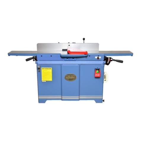
Oliver 4235 User manual

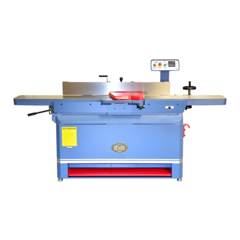
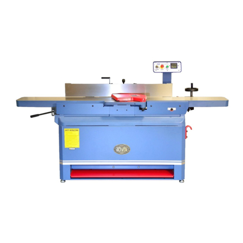
4235 8” Parallelogram Jointer
Owner’s Manual
Oliver Machinery M-4235 8/2019
Seattle, WA Copyright 2003-2019
info@olivermachinery.net www.olivermachinery.net

CAUTION:
Before using this 8” Parallelogram Jointer, read
this owner’s manual completely and follow all
its safety and operating instructions.
QUESTIONS?
If you have any questions or issues with this
jointer, please call our Customer Service
Center at 1-800-559-5065 or visit our website
at www.olivermachinery.net.
SAVE THESE INSTRUCTIONS AND MAKE
THEM AVAILABILE FOR OTHER USERS.

TABLE OF CONTENTS
Warranty Information…..................
4
Operation………………………….
30
Warning………………………………
5
A. Switch Assembly………………
30
Electrical Requirement & Safety…
6
B. Know Your Workpiece………...
30
Important Safety Instructions…….
7
C. Fence……………………………
31
Product Specifications…………….
12
D. Set Depth of Cut……………….
31
Product Overview…………………..
13
E. Hand Position………………….
31
Uncrate Your Jointer………………
14
F. Surfacing……………………….
31
Preparation for Set Up…………….
15
G. Edge Jointer……………………
32
Assembly & Installation……………
16
H. Beveling………………………...
32
16
I. Rabbeting………………………
33
A. Cutterhead Guard......................
B. Dust Collection..........................
16
Maintenance………………………
34
Adjustments…………………………
17
Troubleshooting………………….
35
17
Parts & Diagram………………….
36
18
Wiring Diagram…………………... 46
18
19
21
21
25
26
26
27
A. Belt Tension……………………..
B. Belt Replacement………………
C. Fence Movement……………….
D. Fence Stops……………………..
E. Fence Removal………………….
F. Table Alignment/Leveling……..
G. Outfeed Table Height
Adjustment………………………
H. Depth of Cut………………….....
I. Rotating or Replacing Inserts....
J. Cutterhead Guard.....................
K. Cutterhead Removal.................
L. Pulley Alignment.......................
29
24

WARRANTY INFORMATION
Oliver Machinery makes every effort to assure that its equipment meets the highest
possible standards of quality and durability. All products sold by Oliver Machinery are
warranted to the original customer to be free from defects for a period of two (2) years
on all parts excluding electronics and motors which are warranted for one (1) year from
the date of shipment. Oliver Machinery’s obligation under this warranty shall be
exclusively limited to repairing or replacing products or parts or components, at its sole
option, determined by Oliver Machinery to be defective. Oliver Machinery shall not be
required to provide other form of indemnity or compensation including but not limited
to compensatory damages.
This warranty does not apply to defects due to direct or indirect misuse, abuse,
negligence, accidents, unauthorized repairs, alternation outside our facilities, lack of
maintenance, acts of nature, or items that would normally be consumed or require
replacement due to normal wear and tear.
OTHER TERMS
To obtain and exercise the warranty right, please call 800-559-5065 or fill out warranty
request form online at www.olivermachinery.net.
Warranty parts are shipped via Parcel or Ground. Additional charge will occur and
charge to customers if express shipping is required.
DISCLAIMER
Under no circumstances shall Oliver Machinery be liable for death, personal or
property injury or damages arising from the use of its products.
Oliver Machinery reserves the right to make changes without prior notice to its
products to improve function or performance or design.
FOR MORE INFORMATION
If you need assistance or have questions beyond what is covered in the scope of this
warranty information, please call 800-559-5065 or email us at
info@olivermachinery.net.
Oliver 4235 Owner's Manual
4

⚠WARNING
Read and understand this manual completely and observe all
warning labels on the machine. Oliver Machinery has made every
attempt to provide a safe, reliable, easy-to-use piece of machinery. Safety,
however, is ultimately the responsibility of the individual machine operator.
With any piece of machinery, the operator must exercise caution, patience
and common sense to safely run the machine. Before operating this
product, become familiar with the safety rules in the following sections.
FAMILIARIZE YOURSELF WITH THE FOLLOWING SAFETY NOTICES USED IN
THIS MANUAL.
California Resident – California Proposition 65 Warning
This product contains chemicals known to the State of California
to cause cancer, and birth defect or other reproductive harm. For more information,
visit www.p65warnings.ca.gov.
Wear proper hearing protection.
Always wear safety googles or safety glasses with side shields
complying with current national standards.
Never alter the cutter head guard or use the jointer with the cutter
head guard missing except when rabbeting. Be sure the guard is in
place and working properly before each use. Do not defeat the
guard.
Keep hands away from rotating cutterhead.
This indicates hazardous situation. If precautions are not heeded,
it could result in serious injury or possible death
This indicates if precautions are not heeded, it may result in
minor or moderate injury, and/or possible machine damage.
Oliver 4235 Owner's Manual
5

ELECTRICAL REQUIREMENT
• Grounding Requirements
This jointer is equipped with a power cord with a
NEMA 6-15p plug, as in FIG. 1, that has an equipment
grounding wire and a ground pin, and it should be plugged
into a properly grounded installed outlet. Never remove
or cut off the grounding prong or modify the plug in any
way. Do not use any adapter plugs.
*If the plug does not match your local requirement, consult with an electrician
to replace it with the proper type.
• Power Supply
This jointer is wired for 220V operation and should be connected to a verified ground
power supply circuit that is 220V 50/60 Hz with an 8 Amp circuit. Use a separate
and proper circuit protection for this tool to avoid electrical hazards or damage to
the tool.
• Use a Proper Extension Cord
The use of extension cord is not recommended for this jointer. If you must use an
extension cord with this jointer, only use it for a temporary basis. When using an
extension cord, make sure it is in a good working condition to prevent short circuits
and any electrical hazards. If any sign of cracking, fraying, wear and/or damage
appears, replace it immediately. Refer the chart below to determine the right gauge
for your extension cord length.
Amperage
on
Machine Tag
Cord Length (feet)
25’
26’ – 50’
51 – 100’
101 – 150’
American Wire Gauge Number
0 – 6
18
16
16
14
6 – 10
18
16
14
12
10 – 12
16
16
14
12
12 – 16
14
12
Not Recommended
This machine must be properly grounded to help prevent
electrical shock and possible fatal injury. Consult with a qualified
electrician if you are uncertain about wiring/electrical
requirements in your area.
FIG. 1
Oliver 4235 Owner's Manual
6

IMPORTANT SAFETY INSTRUCTIONS
•IF YOU ARE NOT PROPERLY TRAINED in the use of a jointer, do not use until
proper training and knowledge have been obtained.
•READ, UNDERSTAND AND FOLLOW the safety instructions found in this manual.
Know the limitations and hazards associated with this machine.
•EYE SAFETY. Wear an approved safety shield, goggles or glasses complying with
current national standards to protect eyes. Common everyday eyeglasses are only
impact-resistant. They are not safety glasses.
•PERSONAL PROTECTION. Before operating the machine, remove tie, rings, watch
and other jewelry, and roll up sleeves above the elbows. Remove all loose outer
clothing and confine long hair. Protective type of footwear should be used. When the
noise exceeds the level of exposure allowed in Section 1910.95 of the OSHA
Regulations, use hearing protective devices. Do not wear gloves.
•GUARDS. Always keep cutterhead and drive guards in place and for every operation
except when rabbeting. Never alter the guard or use the tool with guards missing. If
any guards are removed for maintenance, DO NOT OPERATE the machine until the
guards are reinstalled.
•WORK AREA. Keep the floor around the machine clean and free of scrap material,
sawdust, oil and other liquids to minimize the danger of tripping or slipping. Be sure
the table is free of all scrap, foreign material and tools before starting to use the
machine. Make certain the work area is well lighted and that a proper exhaust
system is used to minimize dust. Use anti-skid floor strips on the floor area where the
operator normally stands and mark off machine work area. Provide adequate work
space around the machine.
•GOOD PERSONAL SAFETY. Always stay alert, watch what you are doing and use
common sense when operating the tool.
•CARELESS ACTS. Give the work you are doing your undivided attention. Looking
around, carrying on a conversation, and “horseplay” are careless acts that can result
in serious injury.
•DRUGS, ALCOHOL AND MEDICATION. Do not operate this machine while under
the influence of drugs, alcohol, or any medication.
Oliver 4235 Owner's Manual
7

Important Safety Instructions Continued
•THIS MACHINE IS DESIGNED FOR SURFACING WOOD PRODUCTS ONLY. Do
not use this Oliver jointer for other than its intended use. Do not use this machine to
cut any kind of metal or substance other than wood. If used for other purposes,
Oliver disclaims any real or implied warranty, and guarantee is null and void.
•KEEP THE TABLES CLEAR of other tools, workpieces and debris.
•CHILDREN, BYSTANDERS AND VISITORS SHOULD BE KEPT OUT of the work
area. They may distract the operator leading to an accident.
•NEVER START THE JOINTER while a workpiece is in contact with the cutterhead.
•KEEP INSERTS SHARP AND CLEAN for the best and safest performance.
•MATERIAL CONDITION. Do not attempt to joint chipboards, panel boards or any
stock containing nails, paint or varnish. BE CAUTIOUS of knots in wood. Knots can
be thrown out of the workpiece or cause kickback.
•SUPPORT LONG LENGTHS OF MATERIAL PROPERLY to maintain control. Use
work supports or stands as needed.
•MAINTAIN A BALANCE STANCE and proper footing at all times when operating
this machine. DO NOT OVERREACH or use excessive force to perform any
machine operation.
•DO NOT STAND ON THE MACHINE. Serious injury could occur if the machine tips
over or if cutterhead is unintentionally contacted.
•HEALTH HAZARDS. Some dust created by power sanding, sawing, grinding,
drilling and other construction activities contains chemicals known to cause cancer,
birth defects or other reproductive harm. Some examples of these chemicals are:
§Lead from lead-based paint
§Crystalline silica from bricks and cement and other masonry products
§Arsenic and chromium from chemically-treated lumber
Your risk from these exposures varies depending on how often you do this type of
work. To reduce your exposure to these chemicals, work in a well-ventilated area,
and work with an approved safety mask or respirator specifically designed to filter
out microscopic particles in dusty work conditions.
Oliver 4235 Owner's Manual
8

Important Safety Instructions Continued
•DISCONNECT ALL POWER SOURCE BEFORE PERFORMING ANY SERVICE,
maintenance, adjustments or when rotating or replacing blades. A machine under
repair should be RED TAGGED to show it should not be used until the maintenance
is complete.
•REPLACEMENT PARTS. Use only genuine Oliver Machinery factory authorized
replacement parts and accessories; otherwise, the warranty and guarantee are null
and void.
•ALWAYS USE PUSH BLOCKS when jointing materials less than 3” in height or
width. NEVER pass your hands directly over cutterhead without a push block. Your
hands must never be closer than 3” to the cutterhead at any time.
•DO NOT joint material shorter than 10”. NEVER joint material narrower or thinner
than ¾” when rabbeting.
Oliver 4235 Owner's Manual
9

Important Safety Instructions Continued
After reading and understand the owner’s manual and all the safety
instructions, and you are ready to use this machine, be sure to follow the
safety instructions of before, while and when done operating the jointer.
Before Operating the Jointer
•Make sure the jointer and its accessories are all assembled and in proper working
order.
•Obtain advice from a qualified person if you are not thoroughly familiar with the
operation of this tool.
•Before making any adjustments, installing accessories or making repairs, the
jointer should always be turned off and disconnected from its power source.
•Check that all guards are in place and return quickly to normal rest positions. If a
guard seems slow to return or “hangs up”, have it adjusted, repaired or replaced
immediately. Never use a tool without a properly operating guard.
•Setup and secure blade inserts and worktables according to this owner’s manual.
•Make sure cutterhead inserts are securely locked in the cutterhead and that the
unused portion of the blades is covered with the guard before tool use.
•Maintain proper adjustment of infeed and outfeed tables.
•Before turning on the machine, remove all extra equipment such as keys,
wrenches, scraps, and cleaning rags away from the machine.
•Avoid awkward operations and hand positions where a sudden slip could cause a
hand to move into the blade.
•Hold workpiece firmly.
•Never reach your hands underneath the workpiece while the cutterhead is
rotating.
Oliver 4235 Owner's Manual
10

Important Safety Instructions Continued
While Operating the Jointer
•Keep your hands, fingers and body away from the cutting area. Contact with a
blade insert will cause serious injury.
•Do not try to remove too much material in one pass. Never remove more than 1/8”
per pass.
•Do not reach into the dust chuteto unclog chips. Stop the tool and unplug it from
the power source. After making sure that cutterhead has stopped, clear the chute
with something other than your bare hand.
•Always besure that the jointer is switched off and unplugged before making any
adjustments.
•Never feed the workpiece inthe direction of cutterhead blade rotation. It can cause
the cutterhead to grab and pull the workpiece.
•Use push blocks to hold down the workpiece to protect your hands and fingers.
Your hands and fingers should never pass directly over the cutterhead when feeding
a workpiece.
When Done Using the Jointer
•Turn off and unplug the jointer when done.
•Lock the jointer to prevent unauthorized use.
•Clean and store the jointer in a safe, dry place after use.
Oliver 4235 Owner's Manual

11

PRODUCT SPECIFICATIONS
MODEL 4235.201 8” X 72” PARALLELOGRAM JOINTER
WITH HELICAL CUTTERHEAD AND BUILT-IN MOBILE BASE
Motor……………………………….……………...………………. 2HP 1PH 220V 8 Amps
Infeed Table Travel…………………………….………..……………………………….1/2”
Cutterhead Speed……………………………….……..…...……5,500RPM V-Belt Driven
Number of Knives………………………………………………………………….36 Inserts
Rabbeting Capacity……………………………….…………...………………………...1/2”
Max. Cutting Width……………………………………………………………………….…8”
Max. Cutting Depth……………………………………………………………………….1/8”
Fence Dimensions…………………………………………………………38” L x 4-1/64” H
Fence Tilts………………………...……………………..……….……………..+/- 45°- 90°
Positive Stops……………………..………….…………………………..……. 90°and 45°
Table Dimensions……………………………………………………………….72” L x 8” W
Dust Port Diameter…………………………………………………………………….4” (x1)
Foot Print……………………………………...…….……………………...39-1/8” x 15-1/8”
Overall Dimensions……………………………………72-1/8” L x 24-1/8” W x 38-3/8” H
Net Weight…………………………………….………………………………………352 lbs
Gross Weight…………………………………………..……………………………..487 lbs
Oliver 4235 Owner's Manual

12

PRODUCT OVERVIEW
Built-In
Mobile Wheel
Mobile Base
Lock Knobs
Push Blocks
& Storage
Lifting Hook
Cutterhead
Guard
Fence
Infeed Table
Outfeed Table
Fence Tilt
Handle
Infeed Table
Adjustment Lever
Depth Scale
& Pointer
Outfeed Table
Adjustment Lever
On/Off
Switch
Rabbeting
Table
90°Stop
CAP Screw
Back Lifting
Hook Location
Fence
Movement Knob
Dust Port
Fence Lock Lever
45°Stop Bolt
Fence
Tilt Lock
90°Stop
Block
Infeed Table
Depth Stop
Release Knob
Rear Access
Panel
135°Stop Bolt
Fence Tilt
Handle
Oliver 4235 Owner's Manual
13

Owner’s
Manual
UNCRATE YOUR JOINTER
•Uncrate the wooden package, remove top crate, as shown in ○
2, and check for
shipping damage. If any signs of shipping damage, call 1-800-559-5065 to report.
•Do not discard any shipping material until the jointer is assembled and running
properly.
Contents are shown in FIG. 2.
1. Jointer Unit
2. Top Crate & Pallet
3. Cutterhead Guard Assembly
4. Hardware Bag
•3mm Hex Wrench
•6mm Hex Wrench
•8x10 Double Wrench
•11x13 Double Wrench
5. Hook Assembly
•Spring Washer x 4
•Cap Screw x 4
•Hook x 2
6. Push Blocks
7. Cutterhead Parts
•Torx Screwdriver x 2
•Torx Screw x 10
•Insert x 5
•Insert Box x 1
8. Owner’s Manual
FIG. 2
Pallet
Top Crate
Oliver 4235 Owner's Manual

14

PREPARATION FOR SET UP
1. Clean and wipe off the rust
preventative on the infeed and
outfeed tables using WD40
degreaser or any similar kind of
degreaser.
2. Cover cleaned surfaces with metal
protectant to prevent rust.
3. This jointer should be placed in a dry
area on a sturdy floor with adequate
lighting and ventilation. Make sure
there is sufficient space around the
machine for operations of largest
size of material that will be
processed on this machine, and for
routine maintenance check.
4. This jointer is equipped with a
mobile base which doesn’t require
power lifting. Before moving the
jointer off the pallet, remove four
wood screws at the base.
5. With an assistance of four people,
slowly walk the jointer off the pallet
and place it on the ground. Roll the
jointer to its prepared location. 7.Place the jointer to its prepared
location and tighten the mobile
base lock knobs as shown in FIG. 4.
6. If powered lifting is desired, Install
the lifting hooks on the machine, one
in the front side and one in the back
as shown in FIG. 3 using the
included 6mm hex. wrench.
Heavy Object!
Multi-Person
Lift Required!
If using power lifting equipment, attach
straps or slings around the lifting hooks
to lift the jointer. DO NOT lift the machine
directly beneath the infeed and outfeed
tables as this may cause misalignment
of the tables.
FIG. 3
FIG. 4
Mobile Base
Lock Knobs
Oliver 4235 Owner's Manual

15

ASSEMBLE AND INSTALLATION
A. CUTTERHEAD GUARD
STEP 1: Insert the guard assembly on
the hole of the rabbeting support
bracket as shown in FIG. 5.
STEP 2: Tighten the set screw
completely as shown in FIG. 5.
STEP 3: Swing the cutterhead guard
away from the fence and release it to
make sure it is installed properly.
B. DUST COLLECTION
This jointer is equipped with a 4” dust
port. To install a dust collection, follow
the steps below.
STEP 1: Attach a 4” dust hose (not
included) to the dust port as shown in
FIG. 6.
STEP 2: Secure the hose with a hose
clamp (not included). Make sure the
hose is attached to the dust port tightly.
DO NOT CONNECT TO POWER
DURING ASSEMBLY & INSTALLATION
FIG. 5
Set Screw
FIG. 6
Oliver 4235 Owner's Manual
16

Pulley
FIG. 9
Approximately
¼” Deflection
ADJUSTMENTS
A. BELT TENSION
After 20 hours of operation, the belt
tension needs to be adjusted due to its
slightly stretch in order to prevent its
slippage and burnt out. To adjust the
belt tension, follow the steps below.
STEP 1: DISCONNECT THE MACHINE
FROM POWER!
STEP 2: Loosen four screws as shown
in FIG. 7 on the rear access panel and
remove the panel as shown in FIG. 8.
STEP 3: with medium index finger
pressure, the belt should push in
approximately ¼” between the pulleys
as shown in FIG. 9. If the belt is
correctly tensioned, go to STEP 6. If
there is too much deflection, follow
STEP 4 to STEP 5.
STEP 4 Loosen 4 sets of motor
mounting carriage bolts and nuts as
shown in FIG. 10. NOTE: DO NOT
COMPLETLELY LOOSEN AND
REMOVE THE CARRIAGE SCREWS
AND NUTS.
FIG. 7
FIG. 10
Motor Mounting
Carriage Bolts & Nuts
FIG. 8
Oliver 4235 Owner's Manual
17

A. BELT TENSION
(CONTINUED)
STEP 5: Press down the motor and
check the belt tension as in STEP 3, if
the tension is correct, tighten motor
mounting carriage screws. If it still is too
much deflection, repeat STEP 5.
STEP 6: Reinstall the rear access
panel.
B. BELT REPLACEMENT
STEP 1: DISCONNECT THE MACHINE
FROM POWER!
STEP 2: Remove rear access panel
door as shown in FIG. 7and FIG. 8 on
A. BELT TENSION on page 17.
STEP 3: Loosen 4 sets of motor
mounting carriage screws and nuts as
shown in FIG. 10 on page 17.
STEP 4: Lift the motor to loosen the belt
and tighten the motor mounting carriage
screws and nuts.
STEP 5: Remove the old belt from
pulleys.
STEP 6: Place a new belt and make
sure the belt is seated in top and bottom
pulley grooves.
STEP 7: Loosen 4 sets of the motor
mounting carriage bolts nuts and re-
tension the belt (See A. BELT TENSION
STEP 3 to STEP 5 on page 17).
STEP 8: Reinstall rear access panel.
C. FENCE MOVEMENT
The fence can slide forward or
backward across the width of the tables
as well as being tilted forward or
backward to any angle down to 45°. To
do so, follow the steps below.
Slide Fence
STEP 1: DISCONNECT THE MACHINE
FROM POWER!
STEP 2: Loosen the fence lock lever as
shown in FIG. 11.
STEP 3: Rotate fence movement knob
as shown in FIG. 11 to move the fence
position forward and backward across
the table width.
STEP 4: When the fence is pushed to a
desired position, tighten the fence lock
lever.
Tilt Fence
STEP 1: Loose the fence tilt handle to
adjust the fence to any angle down to
45°.
STEP 2: Tighten the fence tilt handle to
secure the fence to any position.
NOTE: There is a plastic piece mounted
to the front fence as a buffer to prevent
scratches on the tables when adjusting
the fence positions as shown in FIG. 12.
FIG. 12
Buffer
Fence Tilt Handle
FIG. 11
Fence
Lock Lever
Fence
Movement
Knob
Oliver 4235 Owner's Manual
18

The fence has preset positive stops of
135°, 90°and 45°. To adjust the fence
to these stops, follow the steps below.
Fence at 135°
STEP 1: DISCONNECT THE MACHINE
FROM POWER!
STEP 2: Loosen fence tilt lock as
shown in FIG. 13.
STEP 3: Rotate 90°stop block up as in
FIG. 13 (It is in down position) to
disengage the fence to stop at 90°
STEP 4: Use fence tilt handle to tilt the
fence backward and slide it back until it
stops at the 135°fence stop bolt.
STEP 5: Lock fence tilt lock and begin
to jointing at 135°bevel.
NOTE: If the 135°fence stop doesn’t
seem to be accurate, follow STEP 6 to
STEP 10.
STEP 6: To calibrate the angle to true
135°, loose fence tilt lock.
STEP 7: Place a 135°measuring device
on the table against the fence as shown
in FIG. 14.
STEP 8: Loosen the 135°fence stop
bolt & nut and adjust it to lie flush
against the fence.
STEP 9: Re-tighten the nut on the bolt.
STEP 10:Lock fence tilt lock.
Fence at 90°
STEP 1: DISCONNECT THE MACHINE
FROM POWER!
STEP 2: Loosen fence tilt lock as
shown in FIG. 13.
STEP 3: 90°stop block is engaged as
shown in FIG. 13 (down position).
STEP 4: Use fence tilt handle to
position the fence to stop at the 90°
fence stop cap screw as in FIG. 13.
STEP 5: Lock fence tilt lock and begin
to joint 90°fence set.
NOTE: If the 90°fence stop doesn’t
seem to be accurate, follow STEP 6 to
STEP 11.
FIG. 13
135°Fence
Stop Bolt
45°Fence
Stop Bolt
90°
Stop
Block
Fence
Lock Lever
Fence Tilt
Lock
90°Fence
Stop CAP
Screw
Fence Tilt
Handle
FIG. 14
Oliver 4235 Owner's Manual
19

STEP 6: To calibrate the angle to true
90°, loose fence tilt lock.
STEP 7: The 90°stop block is in down
position as in FIG. 13 on page 19.
STEP 8: Slide the fence to approximate
90°,and place a 90°measuring device
on the table against the fence as shown
in FIG. 15.
NOTE: If the 45°fence stop doesn’t
seem to be accurate, follow STEP 6 to
STEP 10.
STEP 6: To calibrate the angle to true
45°, loose fence tilt lock as in FIG. 13.
STEP 7: Place a 45°measuring device
on the table against to the fence as
shown in FIG. 16
STEP 9: Loosen the 90°fence stop cap
screw and nut as in FIG. 13, and slide
the fence to lie flush against the 90°
measuring device.
STEP 10:Re-tighten the cap screw and
nut on the bolt.
STEP 11:Lock fence tilt lock
Fence at 45°
STEP 1: DISCONNECT THE MACHINE
FROM POWER!
STEP 2: Loosen fence tilt lock as
shown in FIG. 13.
STEP 3: Rotate 90°stop block up as in
FIG. 13 (It is in down position) to
disengage the fence to stop at 90°.
STEP 4: Use fence tilt handle as in FIG.
13 to tilt the fence forward and slide it
until it stops at the 45°fence stop bolt.
STEP 5: Lock fence tilt lock and begin
to jointing at 45°bevel.
STEP 8: Loosen the 45°fence stop bolt
& nut and adjust it to lie flush against
the fence.
STEP 9: Re-tighten fence stop bolt &
nut.
STEP 10:Lock fence tilt lock.
FIG. 15
FIG. 16
D. FENCE STOPS (CONTINUED)
Oliver 4235 Owner's Manual
20
Other manuals for 4235
1
Table of contents
Other Oliver Power Tools manuals

Oliver
Oliver 4265 User manual

Oliver
Oliver 4240 User manual

Oliver
Oliver 4265C Instruction Manual

Oliver
Oliver M1013 User manual

Oliver
Oliver 4255 User manual

Oliver
Oliver 4235 User manual

Oliver
Oliver 7660.002 User manual

Oliver
Oliver 4220 User manual

Oliver
Oliver 10044 User manual

Oliver
Oliver 10060.001 User manual