Preeflow eco-REMOTE Wiring diagram
Supplementary instructions
to the Operating Instructions eco-CONTROL EC200-K (B)
Copyright © - Page 1 - Version 1.12
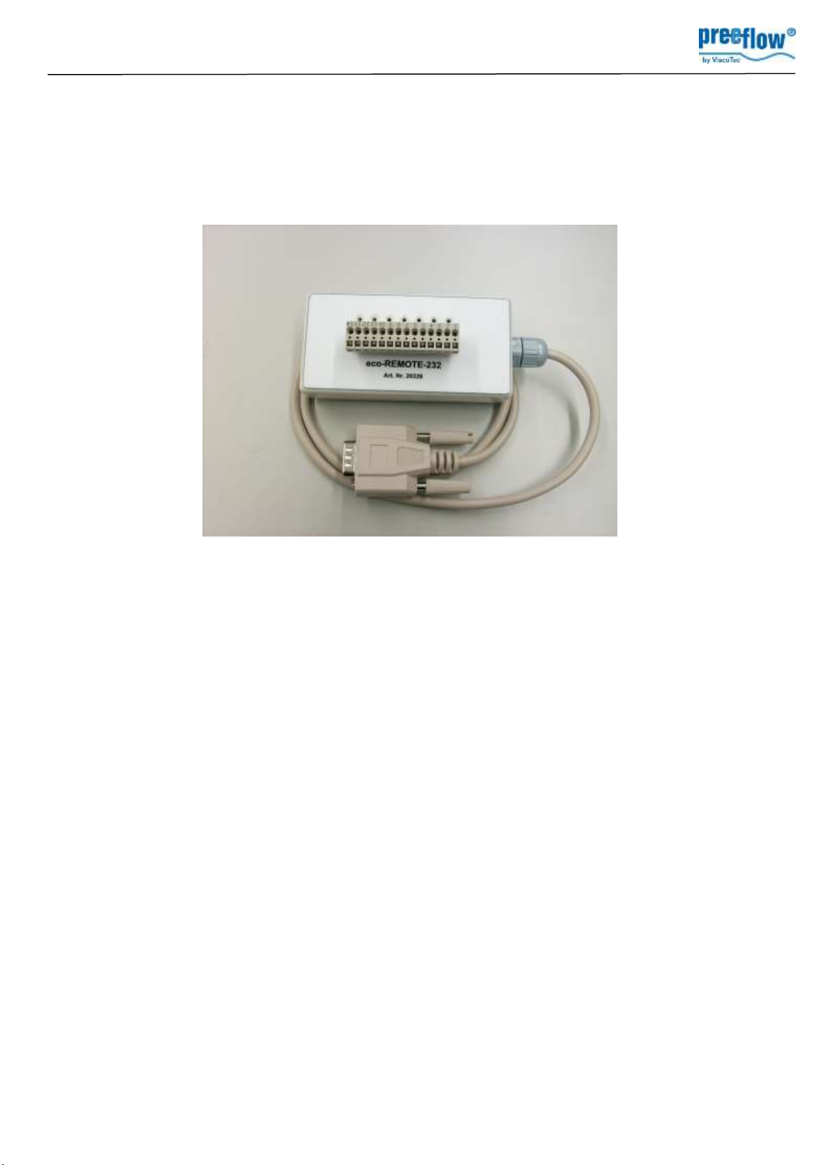
eco-REMOTE
1. Use
eco-Remote is an interface between the eco-Control EC200-K (B) control system and an external
controller (e.g. a PLC). It allows the activation of the dosing programs that are on the memory card of the
control system.
2. Operation
When input 5 is energized, the program number (0 to 24) resulting from the signal values at inputs 0 to 4
is transmitted to the control system. This program is now activated on the control system. The front
keypad is disabled while input 5 remains energized. Initialization is caused by an electrical signal at the
control system.
3. Connecting eco-Remote
Plug the connector (RS232) into the control system which must be switched off. Make the power supply
and connections at the terminal block (15) (see 5. terminal block / signal values).

Supplementary instructions
to the Operating Instructions eco-CONTROL EC200-K (B)
Copyright © - Page 2 - Version 1.12
4. Switching on eco-Remote
1. The power for the eco-Remote is supplied by the attached EC200 (DSUB connector). If required,
the eco-Remote could be supplied by an external 24V source connected to terminals 1 + 2
2. Switch on eco-Control
It’s not allowed to set input 5 (terminal 13) on high level during Switch on of the eco-Control. The LED
next to terminals 1 + 2 will flash during startup of the eco-Remote. The connection with the control
system is established after approx. 15 seconds and the LED lights up.
Table 1: LED status lights
lights up
Connection to the control system has been made, waiting time
approx. 15 seconds.
flashes twice quickly
Input 5 is energized, data* is being sent to the control system,
the front keypad of the control system is disabled.
flashes once quickly
Input 5 has been deactivated, data transfer to the control
system stops, the front keypad on the control system is
enabled again.
flashes continuously
• Connection to the control system is not possible
• No SD memory card plugged into the control system
• Wrong software version of the control system
* Signal values of inputs 0 to 4
Supplementary instructions
to the Operating Instructions eco-CONTROL EC200-K (B)
Copyright © - Page 3 - Version 1.12
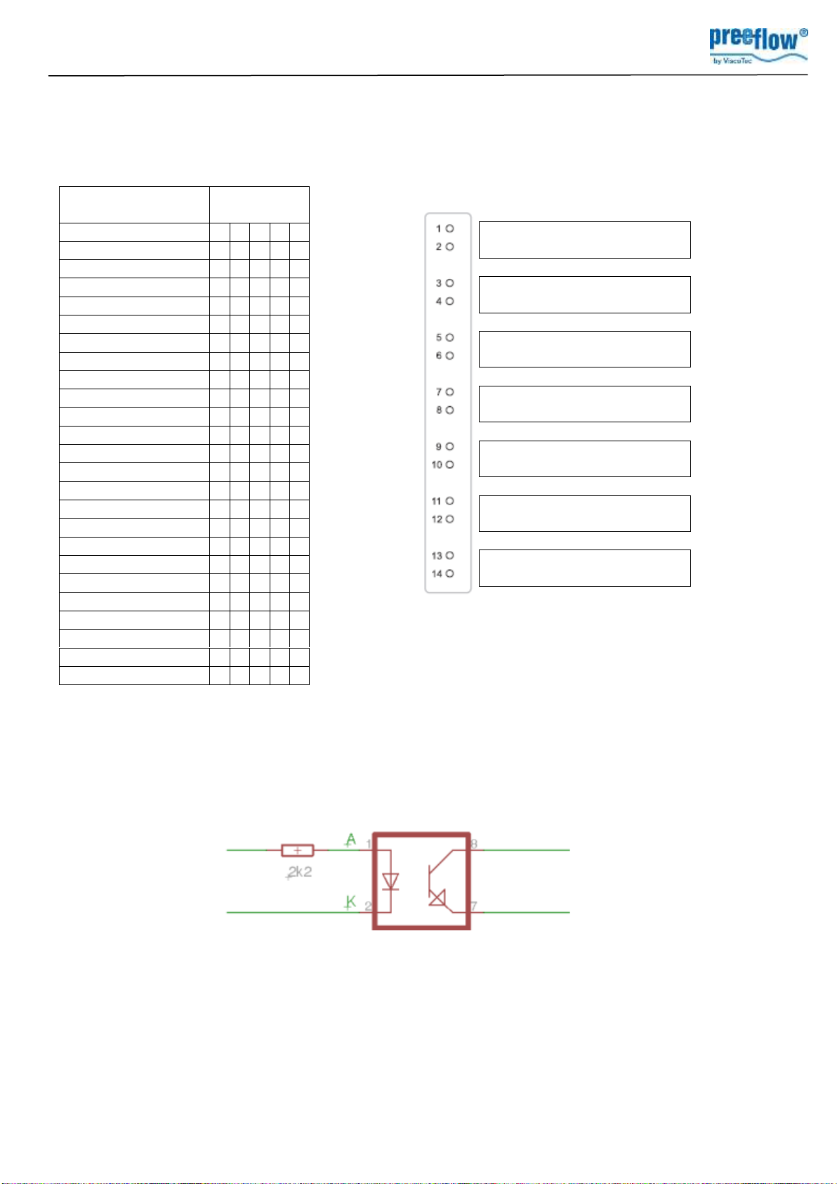
Interne Beschaltung der Optokoppler
5. Terminal Block / Signal Values
Table 2: Assignment of inputs 0 to 4 Table 3: Terminal block
Program number
0
1
2
3
4
0
0
0
0
0
0
1
1
0
0
0
0
2
0
1
0
0
0
3
1
1
0
0
0
4
0
0
1
0
0
5
1
0
1
0
0
6
0
1
1
0
0
7
1
1
1
0
0
8
0
0
0
1
0
9
1
0
0
1
0
10
0
1
0
1
0
11
1
1
0
1
0
12
0
0
1
1
0
13
1
0
1
1
0
14
0
1
1
1
0
15
1
1
1
1
0
16
0
0
0
0
1
17
1
0
0
0
1
18
0
1
0
0
1
19
1
1
0
0
1
20
0
0
1
0
1
21
1
0
1
0
1
22
0
1
1
0
1
23
1
1
1
0
1
24
0
0
0
1
1
Input
A +24V
DC
K GND
A +24V
Input 0
K GND
A +24V
Input 1
K GND
A +24V
Input 2
K GND
A +24V
Input 3
K GND
A +24V
Input 4
K GND
A +24V
Input 5
K GND
Supplementary instructions
to the Operating Instructions eco-CONTROL EC200-K (B)
Copyright © - Page 4 - Version 1.12
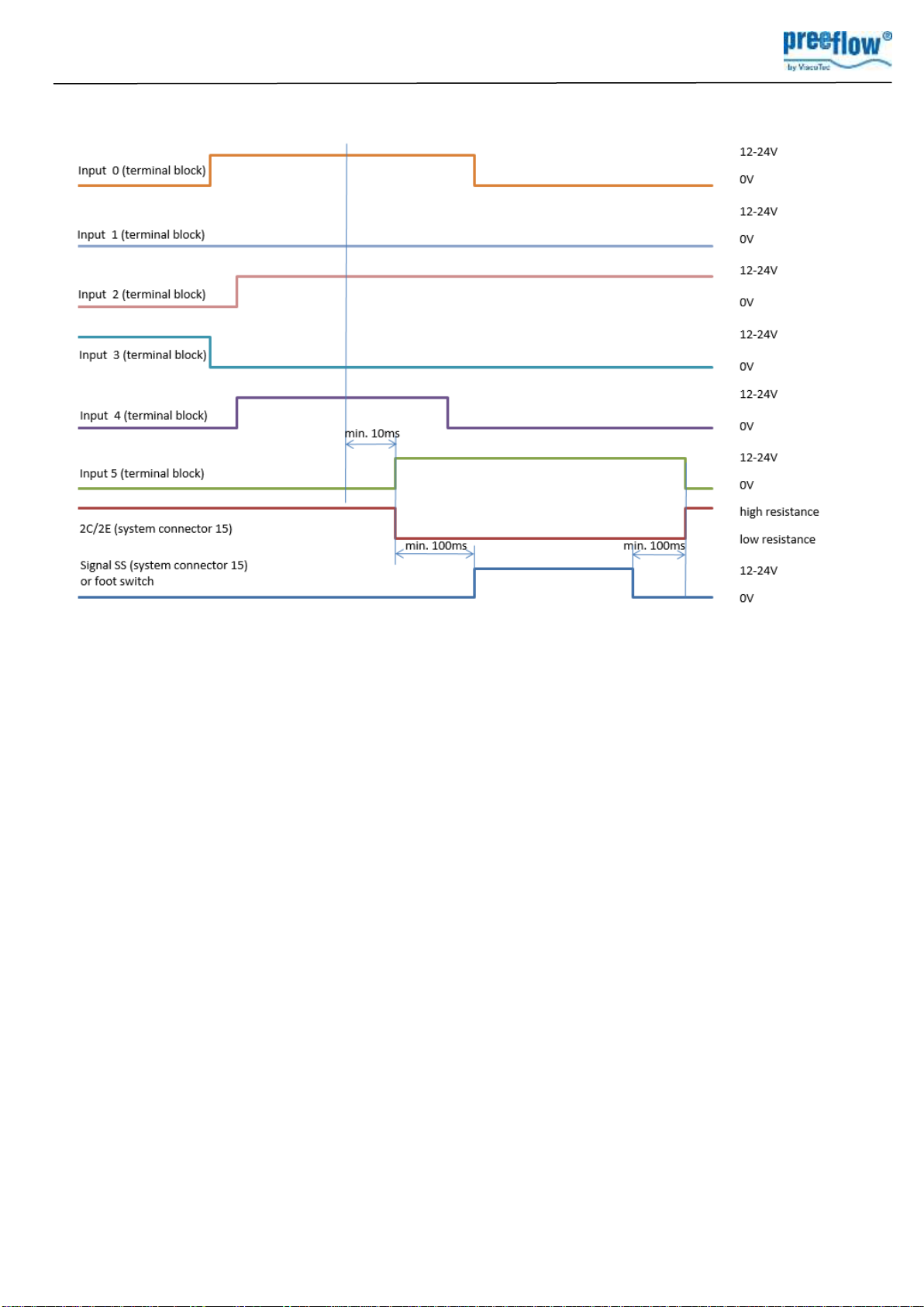
6. Signal forms and levels
7. Signal sequence, logic
1. Energise inputs 0-4 on the terminal block (dosing program number). The above example shows
address 10101 = program number 21.
2. Energize input 5 on the terminal block. Now, the dosing program defined by the level on inputs 0-4
will be activated, the dosing program (see 1.) Please note, that between the last level change on
inputs 0-4 and the energizing of input 5 (level change from low to high) there should be a delay of
at least 10ms. As long as this input is on high level, an “R” followed by the actual number of the
program is shown in the upper left corner of the display. If input 5 is on low level or left open, the
keypad of the eco-Control can be used and in the upper left corner of the display an “L” is shown.
As long as the input 5 is on high level and until the end of the dosing, the output 2C/2E is on low
resistance.
3. If 2C/2E is low resistance (system connector 15), the control system is in Remote operating mode
and can be activated.
4. Between activating of input 5 and the start of the dosing there should be a delay of at least 100ms.
For starting the dosing program either:
- apply - Signal SS, ext. Start, 1C/1E (system connector 15)
or - activate the foot switch (optional, connector 18)
The input 5 still has to be energized for minimum 100ms after the dosing stops!
Quantity and time programs should never run longer than the input 5 is on high level.
5. Once the dosing program is complete, the 2C/2E switches to high resistance (system connector 15).
The control system returns to Local operating mode. On the left upper corner of the display a “L”
appears. Another dosing program can be sent (1. to 3.) and executed (4.).

Supplementary instructions
to the Operating Instructions eco-CONTROL EC200-K (B)
Copyright © - Page 5 - Version 1.12
8. Troubleshooting
Table 4: error cause
Error
Possible Reason
all LED’s off on eco-Remote
eco-Remote not connected to eco-Control
Eco-Remote connected to eco-
Control, but no „L“ or „R“ + program
number on display
eco-Remote connected to eco-Control after switch on
of eco-Control
Input 5 (terminals 13/14) on high level during startup
of eco-Control
„R“ + program number is shown on
display but disappears
Input 5 of eco-Remote on low level or left open
not possible to use keypad on eco-
Control
Eco-Control is in Remote-mode („R“ shown in left
upper corner of display)


