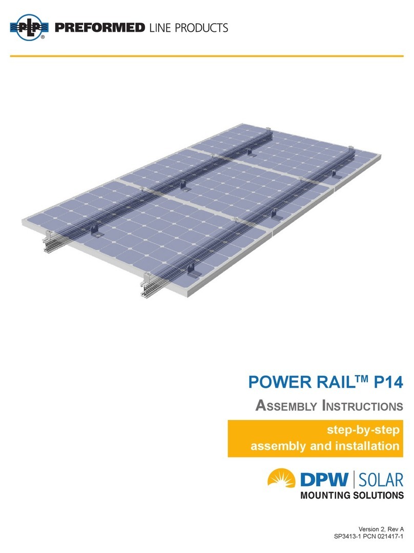
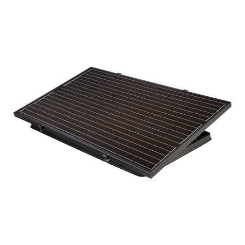
PREFORMED LINE PRODUCTS POWER RAIL 60 Cell User manual

Assembly InstructIons
step-by-step
assembly and installation
Assembly InstructIons
SP3504
POWER RAILTM ‒ TWO-TIER TILT KIT

SAFETY CONSIDERATIONS
This application procedure is not intended to supersede any company construction or safety
standards. This procedure is offered only to illustrate safe application for the individual. FAILURE TO
FOLLOW THESE PROCEDURES MAY RESULT IN PERSONAL INJURY OR DEATH.
Do not modify this product under any circumstances, except where noted in this application procedure.
This product is intended for use by trained technicians only. This product should not be used by anyone
who is not familiar with, and not trained to use it.
When working in the area of energized lines, extra care should be taken to prevent accidental electrical
contact. Be sure to wear proper safety equipment per your company protocol.
For proper performance and personal safety, be sure to select the proper size PREFORMED™
product before application.
PREFORMED products are precision devices. To ensure proper performance, they should be stored in
cartons under cover and handled carefully.

Assembly Instructions, POWER RAILTM ‒ Two-Tier Tilt Kit 1
POWER RAILTM ‒ Two-Tier Tilt Kit
About these instructions:
• The instructions do not include any
information on the selection or installa-
tion of attaching hardware to be mount-
ed to the roof substrate or concrete
foundation. For information on com-
patible roof attaching hardware, see
our publication titled “POWER RAILTM
Design Guidelines”.
• Begin after all attaching hardware has
been installed and secured to the roof
substrate or concrete foundation.
• They are intended to be used by individ-
uals with sufcient technical skills for the
task. Knowledge and use of hand tools,
measuring devices and torque values is
also required.
• Included, are various Notes, Cautions,
and Warnings that are intended to assist
in the assembly process and/or to draw
attention to the fact that certain assembly
steps may be dangerous and could cause
serious physical injury and/or damage to
components. Follow the procedures and
precautions in these instructions carefully.
For questions on a specic installation, please:
Contact us by Phone: 800-260-3792
Send an Email request: info@PLPSolar.com
WARNING
Follow the
procedures and
precautions in
these instructions
carefully.
Periodic Inspection
PLP recommends a periodic re-inspection to
check for any loose components or any corro-
sion. If any loose components and any corrosion
is found, the affected components are required to
be replaced immediately, with the original mount-
ing system manufacturer’s component parts.
Required Tools
o
3/4 inch wrench or socket for 1/2 inch
hardware
o1/2 inch wrench or socket for 5/16 inch
hardware
oTorque wrench
oRatchet wrench
oRatchet extension bar
oFraming square
oTape measure

2 Assembly Instructions, POWER RAILTM ‒ Two-Tier Tilt Kit
Two-Tier Tilt Kit Main Components
There are seven main components and attaching hardware.
Strongback
Rail to Rail
Bracket
Rail
Rail Splice Plate
Leg
Cross Brace
“L” Foot
AMP Clamp
Bonding Mid Clamp
Factory Assembled
(patented)
RAD End Clamp
Factory Assembled
(patented)

Assembly Instructions, POWER RAILTM ‒ Two-Tier Tilt Kit 3
Spacing Calculations (16 Inch on Center Joists)
Module
Type
Angle, ϴ
(degrees)
Tilt Leg
Length,
H (in.)
Span
Length,
X (in.)
Canlever
Length,
C (in.)
Foot
Spacing,
Y (in.)
Strongback
Length,
(in.)
60 Cell
15 23.3 84 42 80
126
25 37.2 84 42 80
35 51 84 42 80
45 64.4 84 42 80
72 Cell
15 26.4 100 50 96
150
25 42.6 100 50 96
35 58.5 100 50 96
45 74 100 50 96

4 Assembly Instructions, POWER RAILTM ‒ Two-Tier Tilt Kit
2 Measure and Mark the “L” Foot and the Leg Attachment Points on the Strongbacks
CAUTION
Span dimensions
are a design spec-
ication. Consult
the design manual
to match these
dimensions to site
conditions. It’s
important to use
the unique span
dimension specic
to the install. Fail-
ure to do so could
lead to excessive
deection and/or
premature system
failure.
To ensure consistency and structural integrity, the
attachment points of the “L” Feet and Legs must be in
accordance with the above diagram and the “Spacing
Calculations” on page 3. Measure and mark each
Strongback to establish attachment points for the “L”
Foot and Leg.
Insert a 1/2”-13 x 1-1/2” Carriage Bolt into channel of
Strongback and slide it down to the previously made
alignment mark. Install the Leg and secure with a 1/2”
Flat Washer, Lock Washer and Nut. Tool tighten for
now allowing the Leg to pivot/rotate as needed and
align to the “L” Foot.
3 Attach the Leg to the Strongback
Leg
Alignment
Mark
1 Install the “L” Feet
Secure the “L” foot to the site-specic anchoring
device such as the foundation, roof structural member,
or surface anchoring device per the device manufac-
turers’ instructions. “Site specic anchoring device”
NOTE
“L” Feet can be
attached directly to
the roof substrate
with the proper
hardware. See
POWER RAIL
Design Guidelines
for more informa-
tion.
Information on
appropriate
anchoring
hardware is
available on an
individual product
basis.
means an appropriate surface attachment for the
roof or substrate in which the Two-Tier Tilt Kit will be
installed.

Assembly Instructions, POWER RAILTM ‒ Two-Tier Tilt Kit 5
5Check the “L” Foot and the Leg Alignment to the Marks on the Strongback and Torque Hardware
Ensure that the “L” Foot and the Leg align to the marks on the Strongback, then tighten the hardware and torque to
45-50 ft.-lbs.
Torque
45-50 ft.-lbs.
Torque
45-50 ft.-lbs.
Torque
45-50 ft.-lbs.
Ensure that the attachment
points align to marks on the
Strongback
Insert a 1/2”-13 x 1-1/2” Carriage Bolt into the channel
of the Strongback and align it to the previously made
alignment mark. Secure with a 1/2” Flat Washer, Lock
Washer, and Nut.
Secure the Leg to the “L” Foot with a 1/2”-13 x 1-1/2”
Bolt, Flat Washers, Lock Washer, and Nut. Tool tighten
for now, allowing for any adjustments in next step.
4 Attach the Strongback and then the Leg to their respective “L” Feet
“L” Foot
Alignment
Mark
Strongback Leg

6 Assembly Instructions, POWER RAILTM ‒ Two-Tier Tilt Kit
6 Install the Cross Brace
Insert a 5/16” x 1” Turn Bolt into the channel of the
Cross Brace, and rotate 90-degrees to lock the Turn
Bolt in place. Secure the ends of the Cross Brace to
the Legs with a 5/16” Flange Nut as shown above.
Center the Cross Brace between the two attachment
points. Torque to 15 ft.-lbs.
Cross Brace

Assembly Instructions, POWER RAILTM ‒ Two-Tier Tilt Kit 7
7Install the Rail-to-Rail Brackets
For Rail-to-Rail Bracket positioning, measure and
mark their four locations along the Strongbacks.
Span and placement of the Rail-to-Rail brackets along
the Strongback is dependent on the module in use
and its clamping locations. If the module manufacturer
has provided specic clamping locations, use those
specications; if none are specied by the manufac-
turer, use a factor of 20-percent of the module length
to determine the N-S positions of the Rail-to-Rail
Brackets. Measure and mark the Strongbacks.
Module Length
Module
Module Length
Module
20% 20% 20% 20%
Rail-to-Rail
Bracket
Insert a 5/16”-18 x 3/4” Turn Bolt into the channel of
the Strongback, aligning it to one of the previously
made alignment marks, and rotate 90-degrees to lock
the Turn Bolt in place. Secure the Rail-to-Rail Bracket
with a 5/16” Flange Nut. Torque to 15 ft.-lbs.

8 Assembly Instructions, POWER RAILTM ‒ Two-Tier Tilt Kit
Splice Plates come in two congurations, 2-hole or
4-hole (above is a 4-hole). Insert 5/16” x 3/4” Turn
Bolts into POWER RAIL and rotate 90-degrees to lock
Turn Bolts in place. Align Splice Plate with center of
splice and secure to POWER RAIL with 5/16” Flange
Nuts. Torque to 15 ft.-lbs.
8 Splicing the POWER RAIL with the Splice Plates (as needed)
Insert a 5/16”x 3/4” Turn Bolt into the channel of the
POWER RAIL, aligning it with the Rail-to-Rail Bracket.
Rotate the Turn Bolt 90-degrees to lock it in place.
Secure with a 5/16” Flange Nut. Torque to 15 ft.-lbs.
9 Install the POWER RAIL
CAUTION
This is a two
person activity. In
addition to the dif-
culties associated
with working on a
sloped rooftop, PV
Modules are heavy.
One person should
hold and align the
modules while a
second person
secures modules
with the clamping
hardware. Failure
to do so could lead
to serious personal
injury and/or dam-
aged components.
10 Install the Modules
The End Clamps must be installed as shown above left, not upside down as shown to the right.

Assembly Instructions, POWER RAILTM ‒ Two-Tier Tilt Kit 9
10 Install the Modules (con’t.)
AMP Clamp bonding Mid Clamps must be installed as shown at above left and not as shown to the right. There
cannot be any visible gaps between the bonding Mid Clamps and the module frames.
The RAD End Clamps are used on the outer Modules.
Insert the 5/16” RAD Bolt into the POWER RAIL and
rotate 90-degrees clockwise to lock the RAD Bolt with-
in the POWER RAIL. Secure with a 5/16” Flange Nut.
Torque to 15 ft.-lbs.
AMP Clamp bonding Mid Clamps are inserted into the
POWER RAIL and positioned between the adjacent
Modules. Insert the 5/16” RAD Bolt into the POWER
RAIL and rotate 90-degrees clockwise to lock the
RAD Bolt within the POWER RAIL. Push the Modules
against the AMP Clamp. Tighten the 5/16” Flange Nut.
Torque to 15 ft.-lbs.
NOTE
The RAD bolts
used in the AMP-
Clamps and the
End Clamps must
be locked into the
channel by rotating
them clockwise
90-degrees. Use
the indicator slot on
the threaded end
to identify whether
or not the bolt has
been locked.

Corporate Headquarters
660 Beta Drive
Mayfield Village, OH 44143
Telephone: 800.260.3792
Fax: 440.442.8816
preformed.com
Email: info@plpsolar.com
© 2019 Preformed Line Products
SP3504
This manual suits for next models
1
Table of contents
Other PREFORMED LINE PRODUCTS Solar Panel manuals
Popular Solar Panel manuals by other brands
BorMann
BorMann BLF2000 installation instructions

Panasonic
Panasonic VBHNxSA series General installation manual
GE Energy
GE Energy GEPV-085-MN installation instructions

Jinyuan Lighting
Jinyuan Lighting EcoMatters JY M72 Series installation instructions
Nice
Nice Solemyo SYKCE Addendum to the manual

Compass
Compass Solar Aluflex 237611 instruction manual
