manuals.online logo
Brands
  1. Home
  2. •
  3. Brands
  4. •
  5. GE Energy
  6. •
  7. Solar Panel
  8. •
  9. GE Energy GEPV-085-MN User manual

GE Energy GEPV-085-MN User manual

Photovoltaic Module Installation Instructions
231 Lake Dr. Newark, Delaware 19702 USA Tel: (302) 451-7500 Fax: (302) 451-7501 Doc. ID#: SM329WI-03
Overview
This document provides information for the
safe installation and operation of your GE
Energy photovoltaic module. Carefully read
this entire instruction sheet prior to product
installation. Information about system sizing,
design, safety, and operation are available
from your respective distributor.
Determine local permit, installation and
inspection requirements before installation. If
not otherwise specified, it is recommended
that the requirements of the U.S. National
Electrical Code (NEC) or respective European
Code be followed.
Applicable Products
This document is applicable to all GE Energy
solar module products.
Cover the module’s front face completely with
opaque material to halt the production of
electricity before making any electrical
connections. Before working on a solar
module, disconnect it from other sources of
electricity, such as batteries.
Only trained personnel familiar with the
principles of electricity and electrical
equipment should install solar modules. Use
properly insulated tools and appropriate
protective equipment.
Solar modules have a protective glass front.
Broken solar module glass is an electrical
safety hazard (electric shock and fire). These
modules cannot be repaired and should be
replaced immediately.
Make sure the modules are arranged such
that the current and voltage characteristics
of the array are within the tolerances of the
device to which the array will connect.
Modules sold in the US are rated up to 600V
while some European modules may be rated
up to 1000V.
In actual usage, a photovoltaic module may
experience conditions that result in more
current and/or voltage than reported at
standard test conditions. The module’s Isc
rating should be multiplied by a factor of 1.25
when determining component ratings. NEC
690.8 requires an additional multiplying factor
of 1.25 for conductor and fuse sizing. Refer to
NEC Table 690.7 for voltage correction factors
that are based on ambient air temperatures.
If NEC Table 690.7 is not available, a factor of
1.25 should be used to adjust voltage.
This module has a Class C Fire Rating and
must be installed over a roof of appropriate
fire resistance. Consult your local building
department to determine approved roofing
materials. Do not install this module integral
with a roof or wall of a habitable structure.
Exception, only the GEPVp-066-G module can
be installed integral with a roof.
Do not artificially concentrate sunlight on
modules. Do not install modules where a
flammable gas may be present. Do not
remove any part installed by GE Energy or
disassemble the module.
Handling and Use
Protective gloves should be worn when
handling solar modules. The gloves will
protect against sharp objects and burns.
This GE Energy module is made using a glass
front cover. Although tough, it is subject to
breakage if not properly handled and
installed. Always transport and store the
module in the shipping container provided.
Do not leave the module unsupported prior to
installation. For example, wind can cause a
module that is leaning against a fence to fall
and break. Avoid application of excessive
bending or twisting forces to the module.
Avoid stepping on the module or subjecting it
to impact.
Mounting
GE Energy solar electric modules can be
mounted using the four mounting holes
located on the solar modules frame or may
also be mounted using pressure clips that
compress the frame from the top to the
mounting rail (figure 1). The mounting rails
must be within one inch (1”) [2.54 cm] of the
frame mounting holes (Figure 2) and run
perpendicular to the length of the module.
Secure the module using the four mounting
holes provided and ¼ in. (6mm) corrosion-
resistant hardware. Lock washers should be
used with this hardware for long-term
security.
Module Specification -GE Energy solar
modules have been designed and tested to a
maximum loading of +/- 50 psf (pounds per
square foot). This loading can be any
combination of snow, ice, or wind. In order for
the solar modules to withstand this loading
the frame must be properly supported. The
frames include four mounting holes at the
proper locations to distribute loading.
Figure 1: Typical pressure clamp
Glass Glass
Mounting Rail
Figure 2: Mounting and placement
GEPV-110-MNA 001
110WATT 16.7VOLTS
21.2VOLTS 6.6AMPS
7.4AMPS 600VOLTS
15AMPS 18 AMPS
CLASSC
xxxxxxxxxxxxxxxx
12AWGMIN.
INSULATEDFOR 75°C M IN.
MADEINUSA
Mounting Rail
Mounting Holes
Hole Location +/- 1"
90°
Hole Location +/- 1"
Drag Force - If the installation is located in an
area that has heavy snow loading or an area
with repetitive freeze thaw cycles, the solar
modules will be subjected to a drag force.
This drag force is the force pulling the
modules at a downward angle (figure 3). To
resist the drag forces the solar module must
have support on the lower edge of the
module frame. It is recommended that the
mounting rails be oriented vertically, placing
the module mounting hardware at the lower
module edge. The solar system designer must
determine the amount of drag force, as more
then 2 mounting clamps may be required for
some sites.
Electric Shock and Burn Hazard
This photovoltaic module produces
electricity when exposed to the sun or
other light sources.
There are typically two or four modules
to a shipping container. These
containers are heavy. To safely transport
these containers multiple people and/or
equipment should be used to avoid
in
j
ur
y
.
Improper mounting of solar modules can
lead to the frame separating from the
glass, the glass breaking, and/or the
solar module (or component used to
construct the solar module) may become
a fallin
g
ob
j
ect.
231 Lake Dr. Newark, Delaware 19702 USA Tel: (302) 451-7500 Fax: (302) 451-7501 Doc. ID#: SM329WI-03
Figure 3: Drag force on module surface
Expansion and Contraction - As the solar
module heats and cools a change in
dimension will occur. As solar modules are
racked side by side this normally small
dimension change soon becomes rather large
at approximately ¼” per 15 feet for
aluminum. To properly account for this
change in dimension, the maximum length of
any array section should not exceed 30 feet.
Once this maximum length is reached the
solar modules and mounting structure will
require an expansion joint. The solar modules
should not straddle the mounting structure’s
expansion joint.
Mounting of GEPVp-066-G ONLY
The GEPVp-066-G module is mounted in a
manner similar to conventional flat concrete
tile roofing products. The exception is that an
approved Class C (or better) Fire Rated roofing
product must be installed on the roof deck
before installation of the GEPVp-066-G
module array.
Selection of the user-supplied substrate-
roofing product depends on local code
requirements, building design and user
preference (an example of a potentially
suitable substrate material is asphalt-
fiberglass composite shingle with Class A Fire
Rating). In the plane of the roof where the
GEPVp-066-G modules are installed, the
substrate roof product should cover the
entire surface, including areas where flat
concrete tile will be installed.
Spacing of the GEPVp-066-G modules should
be set so that reveal length is no more than
13.5” and no less than 13.0”. In order to
minimize shading losses at low sun angles,
the reveal should be kept as close as possible
to 13.5”. The GEPVp-066-G module array
should be located on the roof so that there
will be a uniform border of standard concrete
roofing tiles.
GEPVp-066-G modules are secured to the
roof deck by means of Z-brackets on the
lower module edge and roofing screws
installed through the upper flange of the
module frame. Once a starter course of
concrete roofing tiles is in place, Z-brackets
are installed over the top edge of the
concrete tiles, two per module. A GEPVp-066-
G module is installed by capturing the lower
module edge under each Z-bracket. The
upper edge of the module is then secured
with three #8 x 1.5” roofing screws with EPDM
bonded washers, using the predrilled holes in
the upper flange of the module frame.
Repeat the installation procedure until the
first row is complete. Complete the
installation of each GEPVP-066-G module row
in the same manner. Successive rows of
modules should stagger the module joint as
in a typical flat concrete tile installation
(approximately 6 inch offset). Care should be
taken when installing concrete tiles above the
solar modules. The overlap should not
shadow the photovoltaic cells.
The remainder of the roof installation should
be completed in a manner consistent with
accepted concrete tile roofing practices and
procedures.
Wiring
Conduit-Ready Junction Box- Remove the
junction box cover being sure to save the
original screws. The terminal strip identifies
the positive (+) and negative (-) module output
polarities (see picture below).
A waterproof cord grip should be used to
prevent water intrusion and wire strain.
To exit the junction box four knockouts are
provided for the field installation of conduit or
waterproof strain relief. Only remove the
knockout selected for use, unused knockouts
must be plugged with an outdoor rated
knockout seal.
Place a flat tip regular screwdriver on the
bottom of the knockout recess as shown
above.
Using a blunt tool of medium weight, lightly
strike the end of the screwdriver.
When the knockout is removed it will typically
remove a small amount of the surrounding
plastic. This is completely normal and
expected.
Strip wire insulation back 5/8 inch (16mm),
insert through the cord grip and under the
appropriate terminal screw. Tighten this
screw securely to 16 in-lb (1.8 N-m). Tighten
the cord grip. When all wires are installed, re-
install the cover using the original screws.
To maintain the applicability of the module’s
UL Listing, use Type USE-2 copper wire, rated
sunlight resistant and 90°C, for all wiring
exposed to the weather. The wire may be
stranded or single conductor. The minimum
Damaging the back sheet will expose live
electrical parts. Use caution when
removing knockouts. If the back sheet of
the module is damaged it must be
repaired to ensure no live electrical
com
p
onents are ex
p
osed.
Placing the screwdriver at the top of the
knockout recess could overly stress and
damage the junction box.
231 Lake Dr. Newark, Delaware 19702 USA Tel: (302) 451-7500 Fax: (302) 451-7501 Doc. ID#: SM329WI-03
wire size is 12 AWG (4 mm2). The maximum
wire size is 8 AWG (10 mm2). For modules
that are certified up to 1000V, use TUV
approved 4.0mm2solar cable.
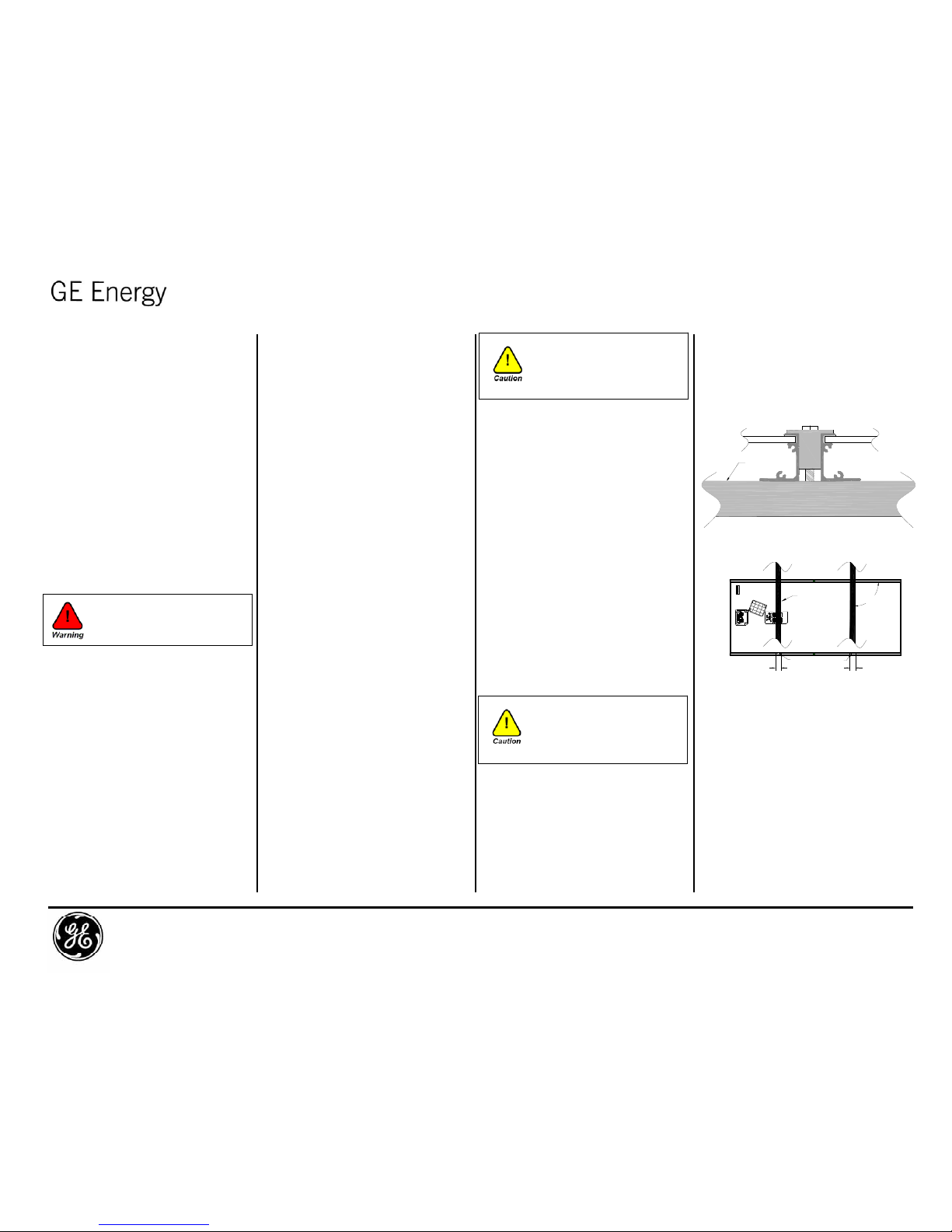
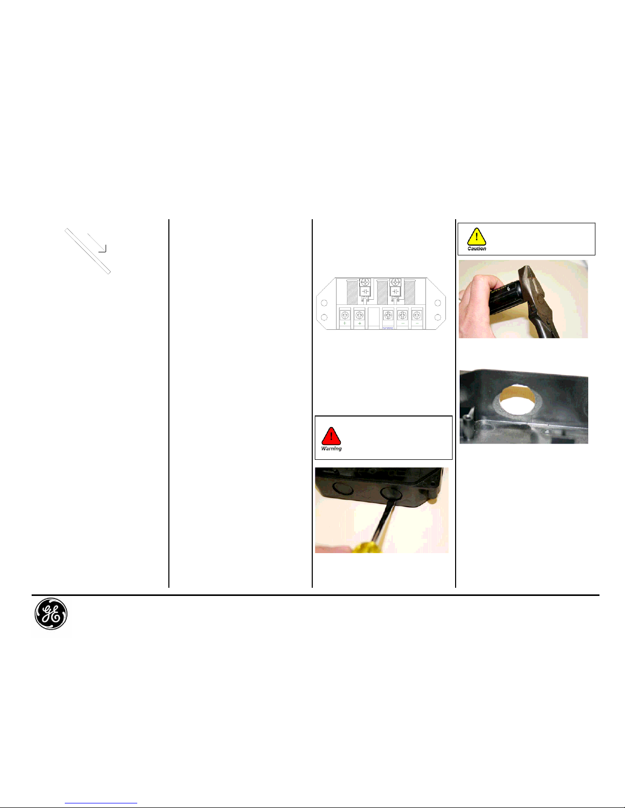
Junction box with Multi-Contact or Solarlok
Leads - When using optional Multi-Contact
(MC) or Solarlok (MS) connectors, there are no
user serviceable parts in the junction boxes.
Do not open the junction box or change inter-
module wiring, as all wiring connections are
performed in the factory. The MC or MS
connectors cannot be opened under load.
Modules may be connected and
disconnected when current is not flowing
through the connector, under open circuit
voltage conditions. Always observe proper
precautions when connecting or
disconnecting modules exposed to light since
hazardous voltage may be present.
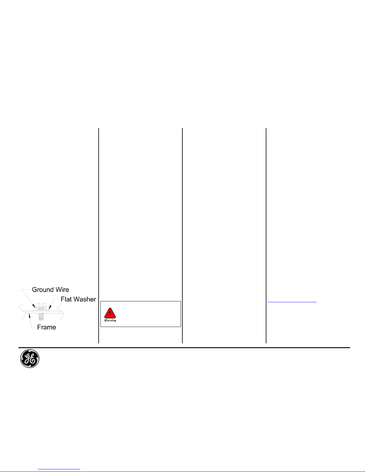
Grounding- Size and earth the equipment
grounding conductor in accordance with
local requirements or the NEC. Attach the
equipment grounding conductor to the
module frame using the hole and hardware
provided. Note that a stainless steel flat
washer is used between the ground wire and
the module frame (see picture below). This
washer is used to avoid corrosion due to
dissimilar metals. Tighten the screw securely .
For optional methods of grounding a solar
module refer to GE Energy Document
“Optional Ground Methods”.
Bypass Diodes- Bypass diodes are pre-
assembled in each GE Energy module.
Typically modules are supplied with a 12 or 18
Amp diode. Do not remove these diodes.
Blocking Diodes and Charge Controllers-
Blocking diodes can prevent the solar module
from discharging the battery at night. GE
Energy modules do not include blocking
diodes. It is recommended that a charge
controller be used to prevent the batteries
from being overcharged and discharged at
night.
Cleaning
Over the life of a solar module, it is common
for dust and dirt particles to accumulate on
the surface of the module. This build up
can reduce the performance of the module as
well as contribute to the growth of moss and
molds. Normally, the build up of dust
particles will be washed away by periodic
rainfall, but in some instances mosses and
molds may appear. If significant moss or
mold growth appears on the module surface
cleaning may be required. To ensure
maximum solar module performance, GE
recommends cleaning the module surface
with a sodium percarbonate solution, similar
to the household-cleaning product
Oxiclean™.
Mixing the sodium percarbonate solution -
Sodium percarbonate is a dry white powder
that can be mixed with warm water to create
an environment-friendly oxidizing agent. The
mixture of sodium percarbonate and warm
water effectively breaks down organic matter.
Do NOT use bleach to clean solar modules, as
it is hazardous to the environment. To create
the cleaning solution, mix 1/2 cup of dry
sodium percarbonate with a gallon of warm
water (100-120° F). The mixture will retain its
cleaning power for 5 to 6 hours.
System preparation and safety precautions-
Cleaning should only be completed by the
system installer or someone with equivalent
fall protection safety training. If you are going
up onto the roof to clean the modules, ensure
that the proper amount of fall protection is
being worn. Follow all warnings at the end of
this technical bulletin.
Applying the cleaning solution to the
modules - Apply the cleaning mixture to the
modules with a clean lawn sprayer. The
sprayer should have a large enough chamber
to hold the entire warm water / sodium
percarbonate solution, it should not be a hose
end sprayer. Once the cleaning mixture has
been applied, let the solution stand on the
modules between 20 and 30 minutes. If
necessary, scrub the module surface to
remove any remaining particles. Thoroughly
rinse the module surface to remove the
cleaning solution. Key points:
• This procedure should only be completed by
the system installer or someone with
equivalent fall protection safety training.
• Fall protection should be worn at all times
while cleaning any modules on a roof-
mounted system.
• Do not drop, allow objects to fall on, stand
or step on solar modules. Do not walk, lean,
sit or rest heavy objects on solar panels.
• Solar modules have a protective glass front.
Broken solar module glass is an electrical
safety hazard (electric shock and fire). These
modules cannot be repaired and must be
replaced immediately. If you have a broken
module turn your system off. If your solar
module is broken do not clean.
• Do not touch the solar modules or the
mounting structures with your bare hands
during the cleaning process. When these
surfaces are exposed to sunlight they can
become extremely hot. Protective gloves
should be worn when touching the system
components.
• Sharp edges may exist on the components.
Protective gloves should be worn while
cleaning the solar array system.
• Exposing the anodized aluminum frame to
the sodium percarbonate cleaning solution
for longer than 10 hours may cause surface
staining on the aluminum.
• The sodium percarbonate cleaning solution
attacks organic matter and should be kept
from directly contacting plants. In the event
the cleaning solution comes in direct contact
with plants that you intend to keep,
thoroughly rinse the plant leaves to remove
the solution.
Performance
Refer to the attached spreadsheet for
performance information. Detailed product
information can be found on the GE Solar
website at:
www.gepower.com/solar
Electric Shock and Burn Hazard
Do not attempt to clean a module with a
broken glass cover or a perforated
backsheet. Such a module can present a
serious shock hazard.
231 Lake Dr. Newark, Delaware 19702 USA Tel: (302) 451-7500 Fax: (302) 451-7501 Doc. ID#: SM329WI-03

This manual suits for next models

7

Popular Solar Panel manuals by other brands

Jinko Solar Tiger Neo JKM N-54HL4-(V) Series installation manual

Jinko Solar

Jinko Solar Tiger Neo JKM N-54HL4-(V) Series installation manual

CanadianSolar Standard Series installation manual

CanadianSolar

CanadianSolar Standard Series installation manual

GOAL ZERO BOULDER 100BC user guide

GOAL ZERO

GOAL ZERO BOULDER 100BC user guide

Qcells SL Series Installation and operation manual

Qcells

Qcells SL Series Installation and operation manual

Qcells Q.PEAK DUO XL-G10.2 Installation and operation manual

Qcells

Qcells Q.PEAK DUO XL-G10.2 Installation and operation manual

Qcells Q.PEAK DUO L-G8 Series Installation and operation manual

Qcells

Qcells Q.PEAK DUO L-G8 Series Installation and operation manual

SwitchBot W1001000 user manual

SwitchBot

SwitchBot W1001000 user manual

SunMaxx Solar ThermoPower VDF20 installation manual

SunMaxx Solar

SunMaxx Solar ThermoPower VDF20 installation manual

Sonnenkraft KIOTO SOLAR Power-60 Series installation manual

Sonnenkraft

Sonnenkraft KIOTO SOLAR Power-60 Series installation manual

Centrosolar CENPAC Series Mounting instructions

Centrosolar

Centrosolar CENPAC Series Mounting instructions

Abexo ELIOX manual

Abexo

Abexo ELIOX manual

Toro 51502 Operator's manual

Toro

Toro 51502 Operator's manual

komodo KDSLRPN21WA user guide

komodo

komodo KDSLRPN21WA user guide

THOMSON 510059 manual

THOMSON

THOMSON 510059 manual

aptos DNA-144-MF26-440W installation manual

aptos

aptos DNA-144-MF26-440W installation manual

Technaxx TX-270 user manual

Technaxx

Technaxx TX-270 user manual

Bushnell TROPHY CAM 119656C instruction manual

Bushnell

Bushnell TROPHY CAM 119656C instruction manual

Sonnenkraft SS20 manual

Sonnenkraft

Sonnenkraft SS20 manual

manuals.online logo
manuals.online logoBrands
  • About & Mission
  • Contact us
  • Privacy Policy
  • Terms and Conditions

Copyright 2025 Manuals.Online. All Rights Reserved.