Solar Mounts Atlantis User manual

Atlantis Ballasted Roof
Installation Manual
Solar Mounts, LLC 300 Woolley Drive, Marshall, MI 49068 www.solargroundmounts.com

Table of Contents
Solar Mounts, LLC 300 Woolley Drive, Marshall, MI 49068 www.solargroundmounts.com
1.0 Installer Notes
2.0 Product Overview and Technical Specs
3.0 Installer Responsibility
4.0 Installer Notes
5.0 Site Selection
6.0 Tools Required
7.0 Components List
8.0 Assembly and Installation Instructions
9.0 Warranty
10.0 Commissioning
11.0 Appendices

Product Overview
Solar Mounts, LLC 300 Woolley Drive, Marshall, MI 49068 www.solargroundmounts.com
Solar Mounts’ Atlantis system is a low-profile ballasted racking
system.
Highlights include:
•G90 coated ballast pans.
•18-8 stainless steel hardware.
•Complete electrical bonding at all connection points.
•Complete wire-routing system (N-S and E-W).
•UL467-listed panel clamps.
•ARRA compliant.
•7-degree tilt.
Key components:
•Trays (North, Mid, South)
•Wireways (N-S, E-W)
•Panel clamps (Mid and End)
•Hardware
•5/16 x 3” Bolt (18-8 SS) Mid and end clamps
•5/16” Lock washer (18-8 SS) Mid and end clamps
•5/16” Flat washer (18-8 SS) Mid and end clamps
•¼-20 x 1” Flange bolt (18-8 SS) N-S pans
•¼-20 Flange nut (18-8 SS) N-S pans
•#12 x ¾” Self-tapping screws E-W bars

Installer Responsibility
Solar Mounts, LLC 300 Woolley Drive, Marshall, MI 49068 www.solargroundmounts.com
The purchaser is responsible for the following:
•Complying with all the applicable local or national codes
including any that may supersede the relevant requirements
stated in this manual.
•Ensuring that the Atlantis™ system components are appropriate
for the particular installation and the installation environment.
•Ensuring that the selected structure can support the Atlantis™
system under actual environmental loading conditions
•Using only Solar Mounts approved parts and installer–supplied
parts as specified by Solar Mounts. Substitution parts may void
the warranty
•Ensuring Solar Mounts’ systems are not installed on roofs with
a slope greater than 3°. (Unless approved by EOR)
•Ensuring safe installation of all electrical aspects of the Solar PV
System
•Ensuring the installation shall be conducted by qualified service
personnel only.
.

Installer Notes
Solar Mounts, LLC 300 Woolley Drive, Marshall, MI 49068 www.solargroundmounts.com
Thank you for purchasing Solar Mounts’ Atlantis™ flat roof top
ballasted racking system manufactured in Michigan. The system
has been configured to accommodate framed (30-51mm thick)
modules. Designed with the installer in mind, the Atlantis™
system allows for a quick installation and easy transportation.
Note: This installation guide must be read in its entirety prior
to installation.
Safety: All regional safety requirements should be followed
when installing the Atlantis system. All equipment/tools
should be properly maintained and inspected prior to use.
This manual is intended for use by professional installers
with a working knowledge of construction principals.
Warning: Solar Mounts’ Atlantis mounting system is
engineered and tested to withstand specific environmental
conditions when installed properly. Failure to do so my
decrease the system performance and/or void the warranty.

Site Selection
Solar Mounts, LLC 300 Woolley Drive, Marshall, MI 49068 www.solargroundmounts.com
Proper preparation of the ground or building rooftop must be
ensured for a well-performing system to be installed. This
includes using proper slip-sheets to protect roof membrane from
panels, racking, and ballast blocks.
For ground mount applications, the Atlantis™ system will typically
be mounted on a flat surface or slightly graded surface facing
South.
For rooftop mount applications, the Atlantis™ system must be
mounted on a debris free surface that passes inspection for
structural support and can withstand the additional PV array load.
General guidelines include:
•Choosing a clear area free of shading
•Preparing a well-drained pad of no more than three (3) degree
slope West to East
•Suggested four (4) foot border surrounding array

Tools Required
Solar Mounts, LLC 300 Woolley Drive, Marshall, MI 49068 www.solargroundmounts.com
The following tools are used for installation of the Atlantis system:
•Layout/BOM from SMLLC
•Open end, 7/16” Box Wrench
•100ft tape measure
•Mason string or chalk line
•3/8” Drive socket wrench with 7/16” Deep Sockets (for 5/16”
bolt on mid/end clamps)
•Suggested impact wrench, torque 12ft-lbs (144 in-lbs.)
•String line
•Concrete or stone ballast (project specific wind load analysis
shall be used to determine minimum weight requirement)
•Slip sheets
•5/16” socket (for #12 self-tapping screws on E-W bars)
•3/8” socket (for ¼-20 nuts/bolts on N-S bars)
Components List
Solar Mounts, LLC 300 Woolley Drive, Marshall, MI 49068 www.solargroundmounts.com
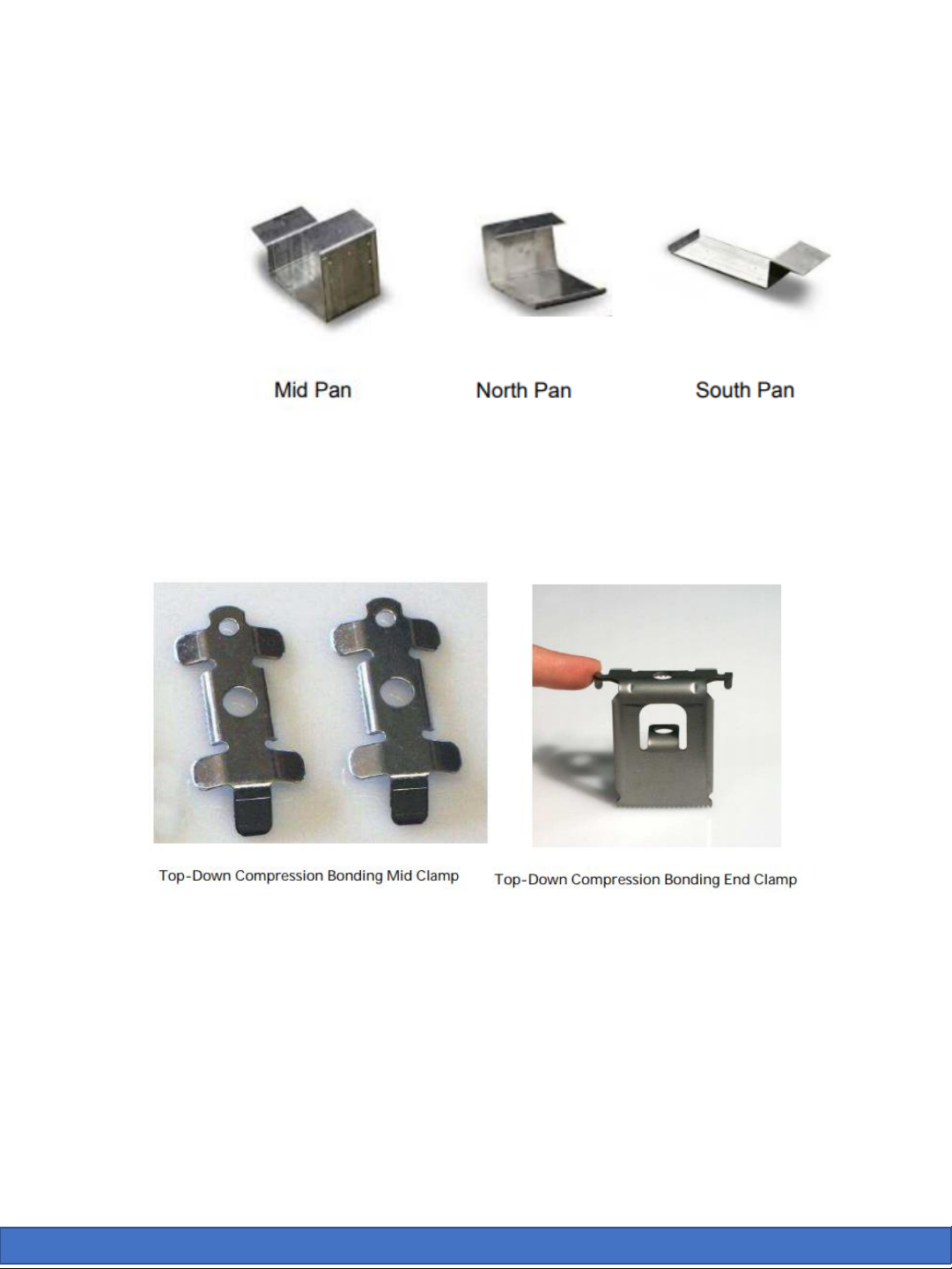
The Atlantis system consists of the following parts:
•Ballast Pans
•Panel Clamps
•Top-down compression bonding Mid-clamp
•Top-down compression bonding End-clamp (30, 35, 40, 45, 50mm)
•5/16 x 3” 18-8 SS bolt w/ lock and flat washer
•Wire Runs
•N-S wireway
•¼-20 x ¾” Flange-bolt and nut
•E-W wireway
•#12 x ¾” self-drilling screws (2/wireway)
•Ballast Bars
•2-Bar adders (15.5” long)
•3-Bar adders (22.89” long)
•4-Bar adders (30.89” long)

Assembly Instructions
Solar Mounts, LLC 300 Woolley Drive, Marshall, MI 49068 www.solargroundmounts.com
1. Create perpendicular lines for array alignment
Using a string line, create an East/West line. Generally this
would be the front or rear of the PV array. Next, establish a
North/South line perpendicular to the first line, near the center
of the array using a multiple of a 3-4-5 triangle. Larger triangles
of 15-20-25 or 30-40-50 should be used for larger arrays.
It is important to perform the layout independent of existing
building structure. Not all parapets or roof edges are square or
parallel. This could result in alignment issues with the PV array.
2. Set E-W tray distance
Use a pre-cut spacer to set the E-W distance between trays. The
spacer length should be:
Panel length (long) + .4” (panel clamp and tolerance)
This should be set from tray center (mounting holes) to tray
center.
Assembly Instructions (cont’d)
Solar Mounts, LLC 300 Woolley Drive, Marshall, MI 49068 www.solargroundmounts.com
3. Set South row of ballast pans
a. Place free edge of end pan along east west line ensuring the
pans remain square.
b. Use pre-measured spacer bar to set the distance between
modules per the formula in step #2.
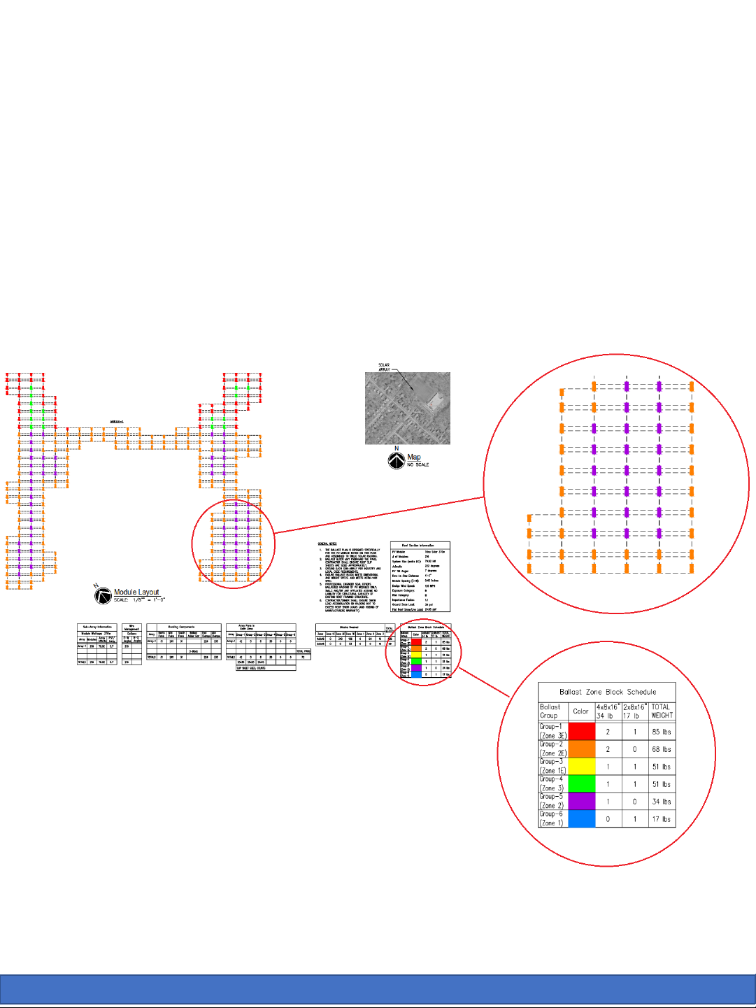
c. Install ballast block in pans to secure location and prevent
movement. Ballast block plans are shown in engineering
drawings provided with SMLLC when requested:

Assembly Instructions (cont’d)
Solar Mounts, LLC 300 Woolley Drive, Marshall, MI 49068 www.solargroundmounts.com
4. Install middle ballast pans
a. Align mid-pans row with corresponding South row pans,
starting in the middle of the array along the N-S string line. E-W
distance between ballast pans can be set using the same spacer
bar from step #3.
b. If N-S pre-placement is critical (in the case of pre-fastening
slip-sheets), the EXACT N-S spacing can be provided on SMLLC’s
layout drawing. Typical N-S spacing is shown below:
c. Install 2, 3 or 4-bar adders per SMLLC drawing.
d. Install ballast block in pans to secure location and prevent
movement.

Assembly Instructions (cont’d)
Solar Mounts, LLC 300 Woolley Drive, Marshall, MI 49068 www.solargroundmounts.com
5. Complete ballast pan layout
a. Align remaining mid-pans rows, starting in the middle of the
array along the N-S string line.
b. Complete array with North row ballast pans. If EXACT N-S is
needed, refer to step #4.
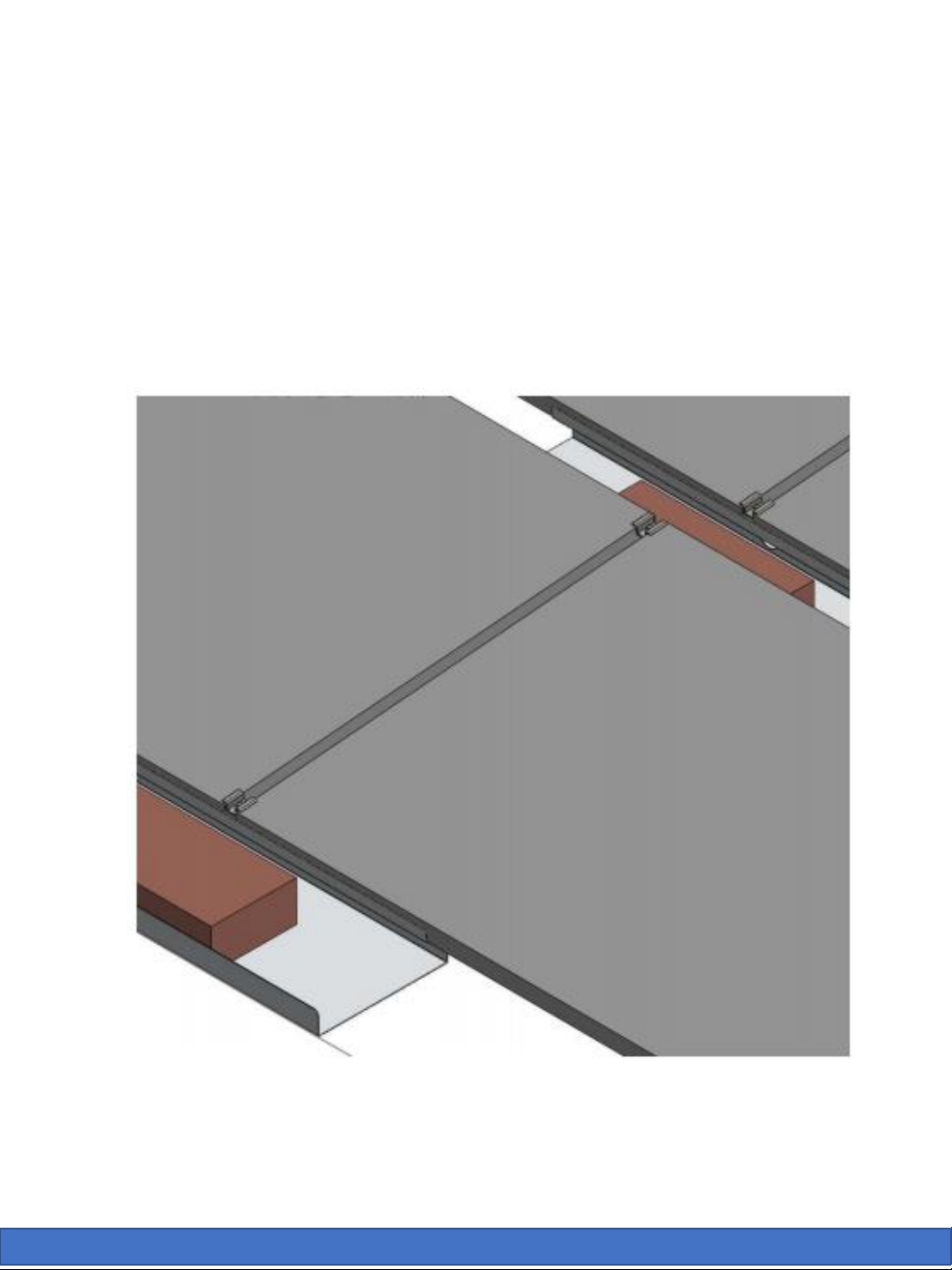
6. Assemble E-W and N-S wireways
a. Connect E-W wireways to ballast pans using #12 self-drilling
screws.
b. Connect N-S wireways (where applicable) to E-W wireways
using ¼-20 hardware.
N-S attachment to E-W wireways
E-W attachment to pans
Assembly Instructions (cont’d)
Solar Mounts, LLC 300 Woolley Drive, Marshall, MI 49068 www.solargroundmounts.com
7. Install modules
a. Begin module installation on the South edge at the center N-S
string line, working outward.
b. Place 2 modules in position and clamp them onto the Mid and
South ballast trays using a mid-clamp and 5/16 x 3” bolt with
lock washer. Bolt will be assembled to trays using pre-
assembled clinch nut. Torque to 12ft-lbs.
Assembly Instructions (cont’d)
Solar Mounts, LLC 300 Woolley Drive, Marshall, MI 49068 www.solargroundmounts.com
c. For ends of rows, an end clamp (and 5/16 x 3” bolt with lock
washer) should be used to complete each row. Torque to 12ft-
lbs.
d. Finish remaining module assembly. Completed array as
shown below:
North
Mids
South

Warranty
Solar Mounts, LLC 300 Woolley Drive, Marshall, MI 49068 www.solargroundmounts.com

Commissioning Report
Solar Mounts, LLC 300 Woolley Drive, Marshall, MI 49068 www.solargroundmounts.com

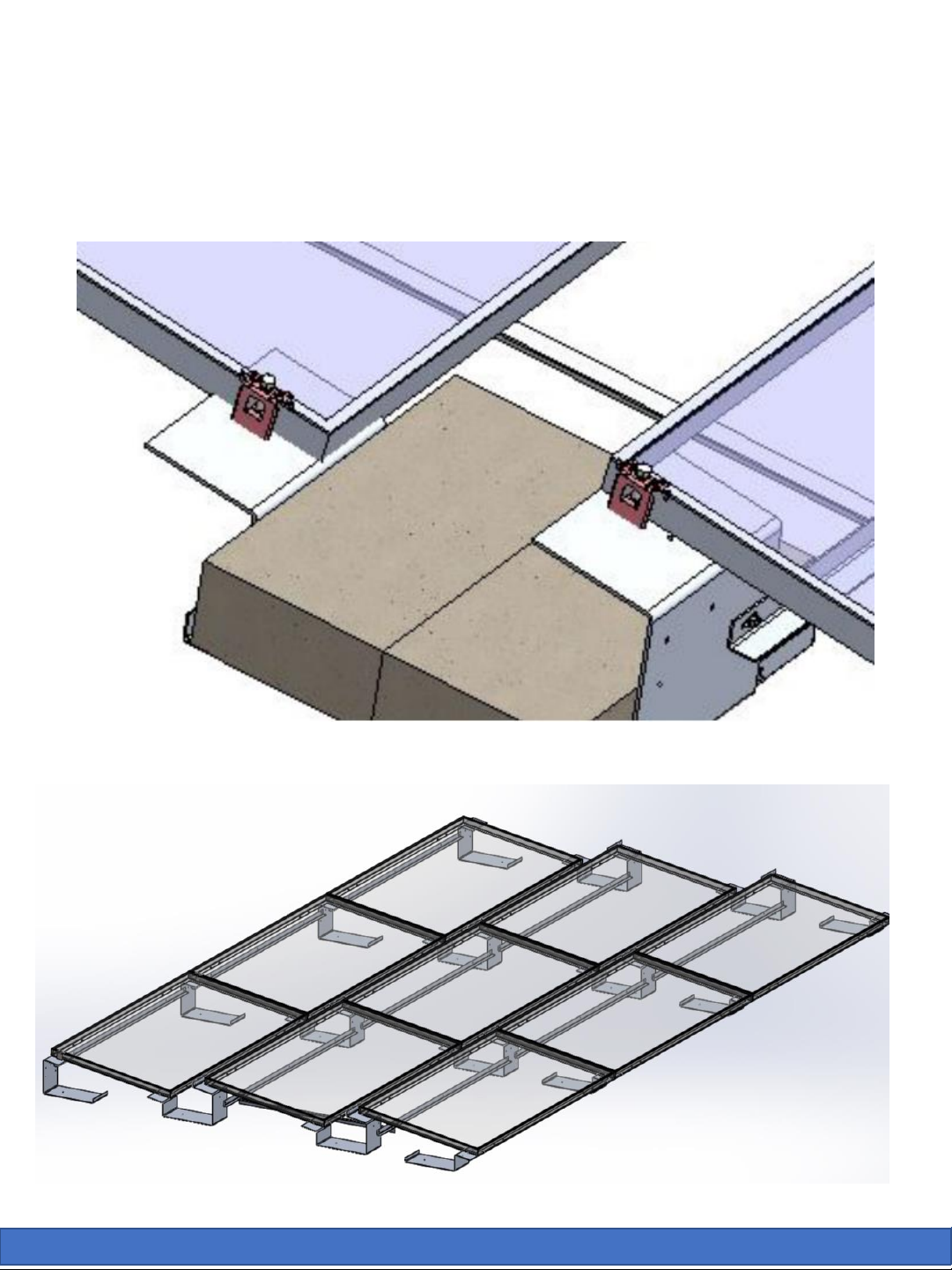
Appendix-A: Full Tray Adder
Solar Mounts, LLC 300 Woolley Drive, Marshall, MI 49068 www.solargroundmounts.com
a. Connect optional tray adders to ballast pans using #12 self-
drilling screws.
b. Required full adder locations are designated on SMLLC
drawings as shown below. Please note that regular ballast
adder bars are NOT required in these locations:
Existing E-W wireways
Optional tray adder

Appendix-A (cont’d)
Solar Mounts, LLC 300 Woolley Drive, Marshall, MI 49068 www.solargroundmounts.com
c. Ballast blocks are added to full adders as shown below:
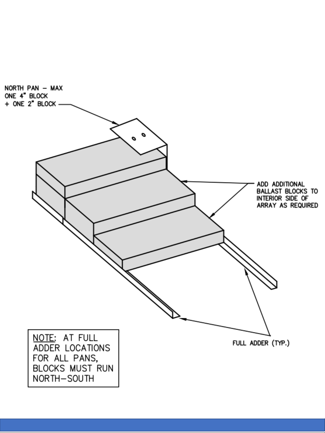
Appendix-A (cont’d)
Solar Mounts, LLC 300 Woolley Drive, Marshall, MI 49068 www.solargroundmounts.com
North Pan:
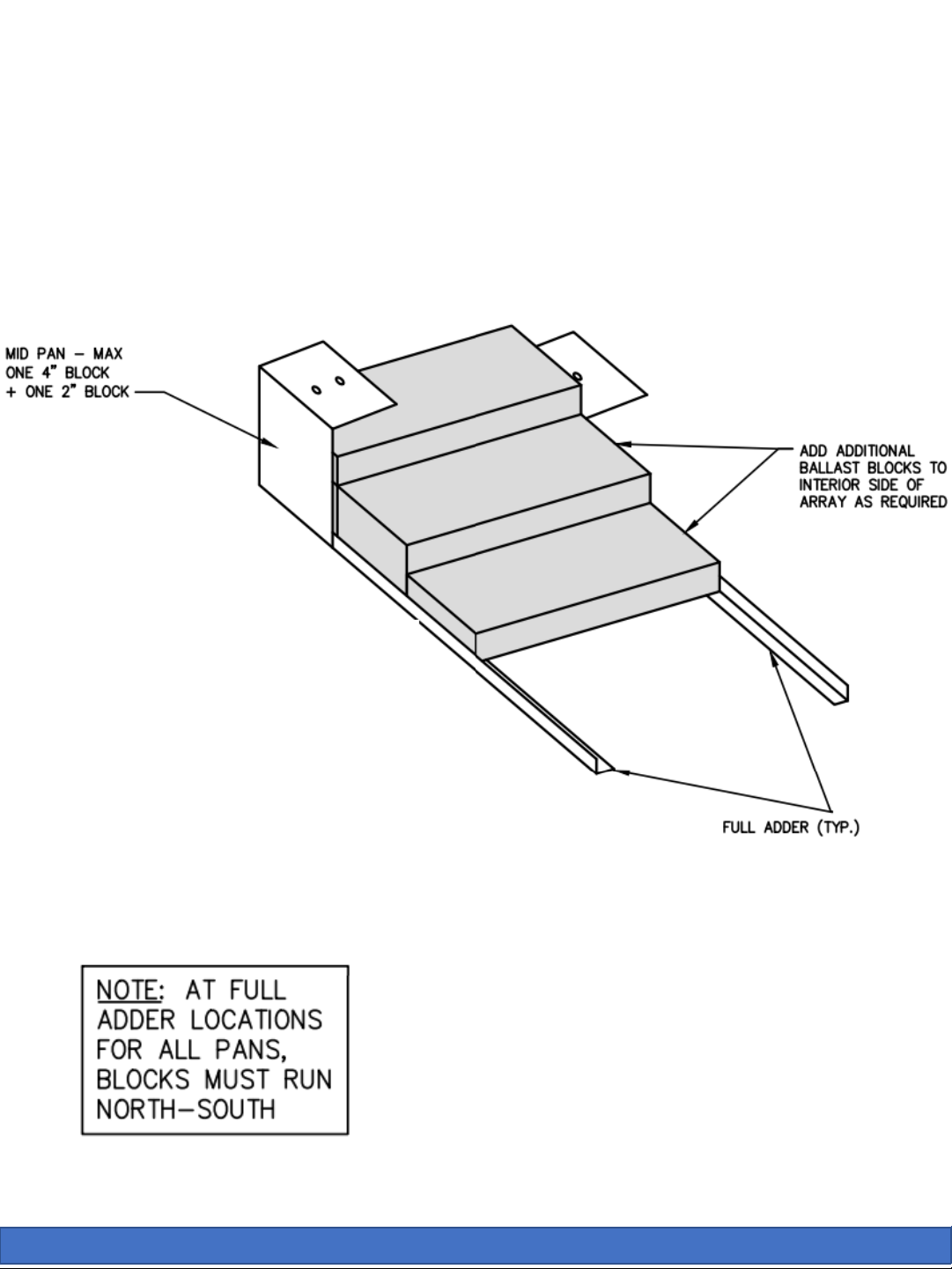
Appendix-A (cont’d)
Solar Mounts, LLC 300 Woolley Drive, Marshall, MI 49068 www.solargroundmounts.com
Mid Pan:
Table of contents
Popular Solar Panel manuals by other brands

Van Der Valk
Van Der Valk ValkField installation manual

TW SOLAR
TW SOLAR TW645MCP-132-H installation manual

Jula
Jula 416-070 Original operating instructions

Wasserstein
Wasserstein Solar Panel For Blink XT and Blink XT 2 Cam user manual

Panasonic
Panasonic HIT Power 225A General installation manual

Mibet New Energy
Mibet New Energy MRac Pole Rack 6 installation guide


PREFORMED LINE PRODUCTS
PREFORMED LINE PRODUCTS POWER RAIL P14 Assembly instructions

Grape Solar
Grape Solar GS-1080-KIT Quick connect guide

Exiom Solution
Exiom Solution EX P-48 Series installation guide

Solar Arc
Solar Arc Smartpool S204 Installation and instruction manual

SunSumSolar
SunSumSolar SPM45-P manual

ECO-WORTHY
ECO-WORTHY ECO-120W user manual