Premier Mounts L180F User manual

INSTALLATION INSTRUCTIONS
L180F
Motorized Flat Panel Lift System*
*Enclosure Not Included
NORTH AMERICA
1321 S. State College Blvd.
Fullerton, CA 92831 USA
USA and Canada –
Phone: 800-368-9700
Fax: 800-832-4888
EUROPE
Unit 3, The Moorings Business Park
Channel Way, Longford,
Coventry, CV79JY, UK
Phone: +44 (0) 2476 644105
Fax: +44 (0) 2476 644165
Other Locations – Phone: (001)-714-632-7100; Fax: (001)-714-632-1044
©Premier Mounts 2013
9534-005-003-00

Page 2 Installation Instructions
L180F
Table of Contents
Preface 3
Warning Statements 3
Parts List 4
Installation Tools 4
Mounting Hole Layout 6
Wiring Instructions 6
Lift Operation 7
Support Bracket Installation 8
Lift Base Installation 8
Base Installation 9
Mount Installation 10
Thread Depth Indicator 11
Attaching the Mounting Brackets 12
Attaching the Mounting Plate 13
Securing the Display 14
Attaching the Floating Lid Bracket 15
Troubleshooting Procedures 16
Programming Lift Height (Optional) 16
Technical Specifications 17
Warranty 18

Installation Instructions Page 3
THE STRUCTURE MUST BE CAPABLE OF SUPPORTING AT LEAST FIVE TIMES THE WEIGHT OF THE DISPLAY AND
LIFT. IF NOT, THE STRUCTURE MUST BE REINFORCED. PROPER INSTALLATION PROCEDURE BY A QUALIFIED
SERVICE TECHNICIAN, AS OUTLINED IN THE INSTALLATION INSTRUCTIONS, MUST BE ADHERED TO. FAILURE TO
DO SO COULD RESULT IN SERIOUS PERSONAL INJURY, OR EVEN DEATH.
DO NOT PLACE DISPLAYS WEIGHING MORE THAN 175LBS. ON THIS MOUNT. IF THIS WEIGHT IS EXCEEDED, DAMAGE TO
THE MOUNT AND/OR LIFT UNIT MAY OCCUR.
PRIOR TO THE INSTALLATION OF THIS PRODUCT, THE INSTALLATION INSTRUCTIONS SHOULD BE READ AND
COMPLETELY UNDERSTOOD. THE INSTALLATION INSTRUCTIONS MUST BE READ TO PREVENT PERSONAL INJURY AND
PROPERTY DAMAGE. KEEP THESE INSTALLATION INSTRUCTIONS IN AN EASILY ACCESSIBLE LOCATION FOR FUTURE
REFERENCE.
Warning Statements
Indicates that the power plug is to be disconnected
from the power outlet.
Safety precautions must be taken at all times.
Warning and Caution statements.
Do not install on a structure that is prone to vibration, movement or chance of impact. Failure to do so could result in damage to the flat panel
display and/or damage to the mounting surface.
Do not install next to any high heat sources. Failure to do so may result in damage to the flat panel display and could increase the risk of
fire.
Contact Premier Mounts with any questions.
In the interest of safety, it is recommended that two perform this installation. Injury and/or damage can result from dropping or mishandling
the flat panel display.
If there is visible damage to the product, it must not be
installed.
This unit is not intended for use by young children of
infirm persons without supervision.
Young children should be supervised to ensure that they
do not play with the unit.
Preface
We are delighted that you have chosen a product from Premier Mounts. Premier Mounts mounting systems are high-tech products that
are based on many years of experience in the manufacture and development plasma displays, LCD diplays and projector mounts. We are
also constantly improving our products to meet our family of customers particular requirements.
These installation instructions will assist and direct you in how to assemble, install and utilize your flat panel lift system.
We are sure that your display lift system will give you many years of problem-free operation. Before our products leave the factory they
undergo full function and quality testing. Should you, nevertheless, experience problems with your system, you are always welcome to
contact our Customer Service department.
Premier Mounts provides a warranty on all of our products. This warranty, however, is subject to correct use in accordance with the
specifications and procedures as set forth in the manual. Maintenance and repairs must be done by a certified technician.
Changes in installation and use of Premier Mounts products can affect their operation and durability. Changes must therefore only be
made at your own risk.
PREMIER MOUNTS DOES NOT WARRANT AGAINST DAMAGE CAUSED BY THE USE OF ANY PREMIER MOUNTS
PRODUCT FOR PURPOSES OTHER THAN THOSE FOR WHICH IT WAS DESIGNED OR DAMAGE CAUSED BY UNAUTHORIZED
ATTACHMENTS OR MODIFICATIONS, AND IS NOT RESPONSIBLE FOR ANY DAMAGES, CLAIMS, DEMANDS, SUITS,
ACTIONS OR CAUSES OF ACTION OF WHATEVER KIND RESULTING FROM, ARISING OUT OF OR IN ANY MANNER
RELATING TO ANY SUCH USE, ATTACHMENTS OR MODIFICATIONS.
L180F
Page 4 Installation Instructions
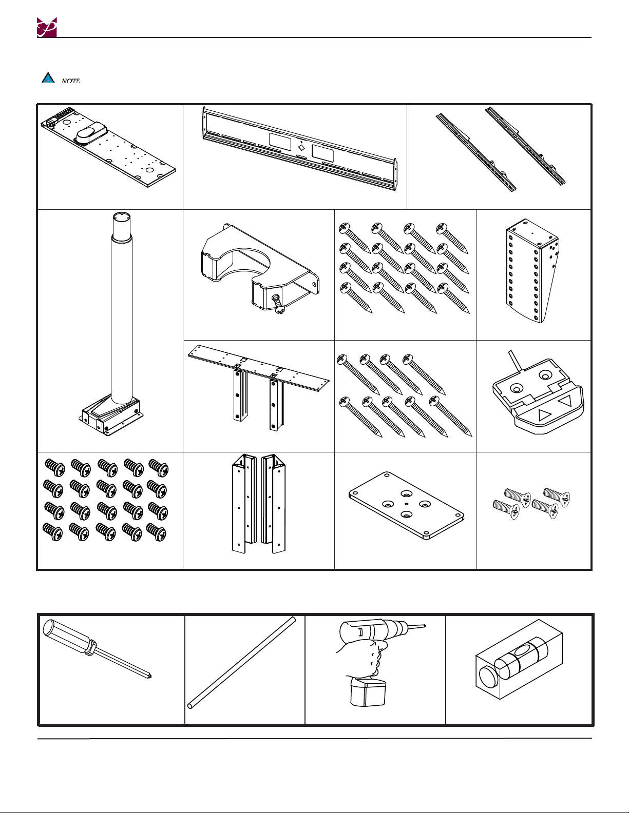
Installation Tools
Screwdriver Thread Depth Indicator Portable Drill
Parts List
This mount is shipped with the following installation hardware and components. Make sure that none of these parts
are missing and/or damaged before beginning installation. If there are parts missing and/or damaged, please stop the
installation and contact Premier Mounts (800-368-9700).
Steel Floor Board (Qty 1)
Manual Switch (Qty 1)
#10 x 3/4” Wood Screw (Qty 9)
Lift (Qty 1)
M6 x 12 Phillips Head
Screws (Qty 20)
Mounting Plate (Qty 1)
#8 x 1/2” Wood Screw (Qty 16) Display Mount (Qty 1)
Mounting Brackets (Qty 2)
Support Brace (Qty 1)
Level (Supplied)
L180F
Floating Lid (Qty 1)
Spacer (Qty 1)
M6 x 20mm Phillips Flat
Head Screws (Qty 4)
Slide Brackets (Qty 2)

Installation Instructions Page 5
The nylon spacers may be stacked to achieve proper spacing.
M8 x 40 (Qty 6)
M6 x 12 (Qty 8)
(Qty 8)
M4 x 25
M4 x 16
M5 x 25
M5 x 20
M5 x 16
M5 x 12
M5 x 50
M8 x 70
M8 x 35
M8 x 30
M8 x 25
M8 x 20
M6 x 20
(Qty 4)
(Qty 8)
(Qty 6)
(Qty 6)
(Qty 4)
(Qty 4)
(Qty 6)
(Qty 4)
(Qty 6)
(Qty 6)
(Qty 6)
(Qty 6)
1
4" Nylon Spacers
(Small)
(Qty 6)
1 Nylon Spacers
(Qty 6)
1
4" Nylon Spacers
(Large)
(Qty 6)
5
16" Nylon Sleeves
(Qty 4)
9
16" Nylon Spacers
(Qty 6)
5
16" Flat Washers
(Metal)
(Qty 6)
1
2" Nylon Spacers
(Large)
(Qty 12)
L180F

Page 6 Installation Instructions
Mounting Hole Layout
Mounting Hole Pattern
1. Single Lift Mounting Points
2. Dual Lift Mounting Points
3. Outlet Electrical Box Mounting Points
4. Steel Floor Board Mounting Points
5. Power Cord Outlet Holes
6. Display On/Off Control Box Mounting Points
7. Control Box Mounting Points
1
1
11
1
1
4444
4
44
4
4
4
33
33
2
2
22
2
22
2
22
2
2
6
66
6
5
5
77
77
Wiring Instructions
Prior to installing the base, the L180F must be wired.
Step 1. Locate the lift control
cable (pre-installed on
lift base)
Step 2. Insert control cable into
Slot #1 of control box.
Step 3. Locate manual
switch.
Step 4. Insert manual switch
cable into the RJ45 plug
on the control box.
Step 5. Attach the switch to the
inside wall of the cabinet
using two (2) #8 x 1/2”
screws.
Step 6. Locate extension power
cord and route through
(pre-cut) holes in base.
Install in an easily
accessible location and
away from moving parts.
L180F

Installation Instructions Page 7
Lift Operation
Console ON/OFF Box Functionality for Display Lift Applications
Systems utilizing the console ON/OFF box will automatically turn on and off a display connected to the system. Power is delivered to
the display when the lift is raised, and removed when the lift is lowered. The system is capable of running up to three lifts in parallel
with impulse functionality and always active Anti-Collision™.
Impulse Activation
When a key is pressed to drive the system up or down, the lift system will continue running after the key is released until it reaches the
stroke limit. If the system comes in contact with a rigid obstruction, Anti-Collision™ will be activated.
The user may also stop travel of the lift system by pressing a button opposite to the present travel direction. For example if the system
is being driven up, pressing the down button will stop the system.
Remote Activation (optional)
When used in conjunction with the IR sensor and remote, the lift system is capable of being operated remotely. To activate the system
in either the up or down direction wirelessly, simply point the remote at the receiver and press the respective button.
Depending on the furniture and screen size of the television, different stroke lengths are sometimes needed. Adjustments in the stroke
may be performed using the IR sensor. Remote activation is performed using the remote.
To set the stroke limit, move the lift to the desired position using the IR sensor. The lift will move on its own after a single button press,
so be sure to press the key opposite to the direction of travel to stop it at the preferred location. Where the lift stops will then be set as
the stroke limit. This stroke limit is only obeyed by the remote.
Anti-Collision™
The anti-collision function is always active when running the system. Anti-collision can limit material damages on a flat screen lift if a
collision with a solid object should occur.
Situations where the Anti-Collision™ does not work
There are situations where the anti-collision will not be activated. These situations are:
If the collision happens during the initialization phase
If the collision happens within the first 1000 msec or after the control button has been released
If the collision happens between the floor and the table and the load on the desk + the weight of the legs are lower than 40 kg
If the collision happens over too long time, e.g. if the collision is with a soft object
Initialization of the lift system
When a system is first assembled it is necessary that the system be initialized. The lift system is initialized by pressing the down button
once or twice and holding it down until the lift runs into end stop, it will then automatically run approximately 3mm out again hereafter,
slowly running in again. Only release the down button when the movement has completely stopped.
If the button is released before the sequence is complete then the initialization is interrupted and must be started again
from the beginning.
Because the lift can be in different modes when initialization starts, it is sometimes necessary to press the down button twice to start the
initialization. If an error situation occurs at the end stop positions, then the lift has to be initialized again.
L180F

Page 8 Installation Instructions
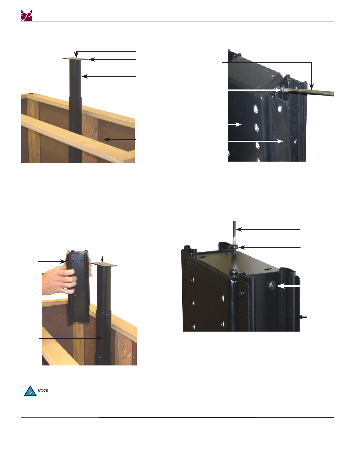
Lift Base Installation
The lift assembly comes pre-assembled.
Step 1. Locate the six (6) mounting points that
are located on the lift base (three on each
side).
Step 2. Determine where the six (6) mounting points are
for the single base installation (see page 5).
Step 3. Place the lift base over the mounting points and
line up the holes.
Steel Floor Board
Lift Base
Step 4. Attach the lift base to the steel floor board using
six (6) M6 x 12 Phillips head screws (three on
each side).
Lift Base
Steel Floor
Base
Mounting Points
Support Bracket Installation
Step 1. Slide the support bracket down the lift
column about 3” from the top of the outer
lift tube.
Step 2. Use two (2) #8 x 1/2” Phillips head wood
screws to attach the support bracket to the
rear of the cabinet.
Step 3. Insert and tighten two (2) M8 x 35
Phillips head screws (one on each side) on
the back of the support bracket. Thread
these screws all the way in.
Wood Screw
Mounting Point
Support
Bracket
Lift
Column
M8 x 35mm
Screw
Tightening the screws will force the tabs
against the lift. Screw all the way in.
L180F

Installation Instructions Page 9
Base Installation
The following steps direct you only on how to attach the lift to a pre-existing mounting surface. These directions will
proceed on the assumption that you have already selected your mounting surface (i.e. furniture enclosure, plywood
base, concrete floor, etc.). Unpack the L180F and familiarize yourself with the components. Please take time before you
install the L180F to determine the location of where the L180F will be mounted. Please familiarize yourself with all
components contained herein.
Step 1. Place the steel floor board on the mounting surface inside the cabinet, making sure that the steel floor board is centered
right to left and positioned against the front inside wall of the cabinet.
Step 2. Locate the nine (9) mounting holes that are on the steel floor board.
Step 3. Using nine (9) #10 x 3/4” wood screws (supplied) and a portable drill, attach the steel floor board to the mounting surface.
All wiring must be completed prior to performing the following steps.
Steel Floor Board
Steel Floor Board
#10 x 3/4”Wood Screw
Drill
L180F
If mounting to concrete, please use commercially available concrete anchors.
Page 10 Installation Instructions
Step 1. Activate the remote and extend the lift
until the lift is in the fully raised position.
Step 2. Place the mounting spacer on top of the
lift.
Step 3. Use four (4) M6 x 20mm Phillips flat head
screws to secure the spacer to the lift.
Mount Installation
Cabinet
Lift
Mounting
Spacer
Step 5. Place the display mount on top of the lift
column.
Lift
Display
Mount
Screwdriver
M6 x 20mm
Mounting
Screw
Be sure to line up the holes on the
display mount with the threaded holes
that are located on the lift.
Side Slide
Bracket
L180F
Step 6. Loosen the six (6) M6 x 12 screws on the
inside of the sliding support bracket.
Step 7. Raise the bracket up to the desired height and
re-tighten.
Step 8. When the lid and slides are inserted, the lid
should be sitting no less then ¼” above the
top of the display.
Step 9. To gain extra height out of the slide support
bracket, use the top four (4) screws only.
This will allow the slide support brackets to
be raised higher.
M6 x 12mm
Mounting
Screw
M6 x 20mm Phillips
Flat Head Screws
Step 4. Attach the slide brackets to the display
mount using twelve (12 - six per side)
M6 x 12mm Phillips head screws.
Slide Bracket
Display Mount
M6 x 12mm Phillips
Head Screw
Screwdriver
Installation Instructions Page 11
/180F
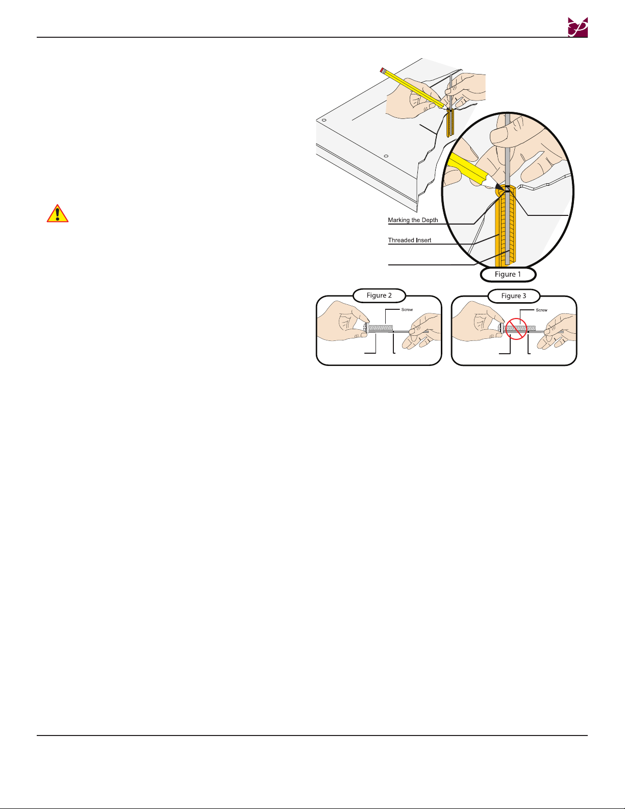
Selecting the Mounting Hardware
Insert a small straw or toothpick into the threaded
inserts found on the back of the flat panel.
® Use a pencil to mark the depth of the threaded insert
on the small straw or toothpick.
¯ Mark the straw or toothpick 1/8” above the depth of
the threaded insert, as shown in Figure 1.
° Insert the small straw or toothpick into the remaining
threaded inserts to compare and verify their depth
using the straw or toothpick’s 1/8” allowance mark.
± Locate the correct diameter screw for the threaded
insert.
If the screw you selected is longer than the 1/8”
allowance mark on the small straw or toothpick,
as shown in Figure 2 and Figure 3, do not use this
screw. The screw length must not bypass the mark.
² Test each size of the screws provided.
The correct screws should thread easily into the
mounting point and not pull out when tension is
applied.
Small Straw or Toothpick
Small Straw
or Toothpick
Small Straw
or Toothpick
Marking the 1/8”
Allowance
Depth Plus 1/8” Allowance
Mark
Depth Plus 1/8” Allowance
Mark
Page 12 Installation Instructions
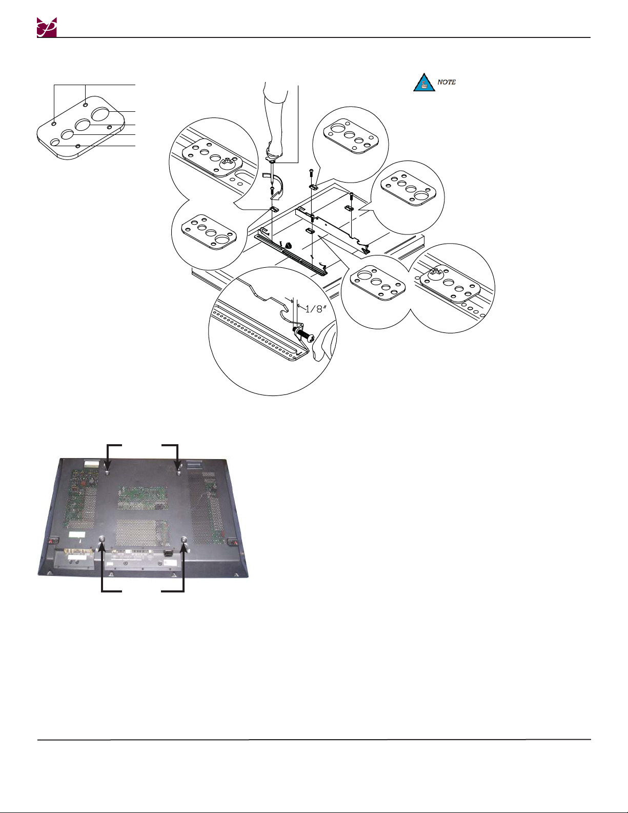
Attaching the Mounting Brackets
Step 1. Place the display on a soft, flat surface,
face-down.
Step 2. Determine where the mounting points are
located.
Step 3. Place the universal brackets over the
mounting points.
Step 4. Once the desired position has been
determined, place the mounting hardware
over each mounting point and secure them
using a screwdriver.
Mounting
Points
Mounting
Points
Phillips Head Screwdriver
DIMPLES
FACING UP
DIMPLES
FACING UP
DIMPLES
FACING DOWN
DIMPLES
FACING DOWN
Dimple
M4
M5
M6
M8
The Griplate™ have M4, M5
M6 and M8 hole patterns to
fit the hardware that your flat
panel requires.
L180F
Installation Instructions Page 13
IT IS RECOMMENDED THAT TWO PEOPLE MOUNT THE DISPLAY, AS THE UNIT IS HEAVY AND, IF
DROPPED, WILL DAMAGE THE MOUNT, THE DISPLAY, AND/OR PERSONNEL.
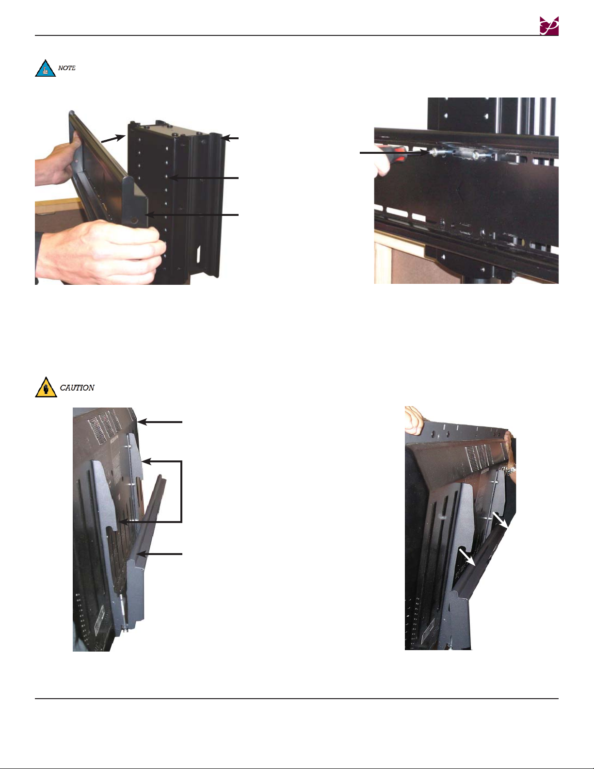
Attaching the Display
Step 1. Place the universal brackets and the
display over the upper mounting rail of the
mounting back plate.
Display
Mounting Brackets
Mounting Rail
Step 2. Lower the universal mounting brackets
and display onto the mounting rail of the
mounting back plate.
Attaching the Mounting Plate
Step 1. Place the mounting back plate against the
display mount and line up the mounting
holes on the mounting back plate with the
mounting points on the display mount.
Step 2. Use four (4) M8 x 16 Phillips head screws
to attach the mounting back plate to the
display mount.
Step 3. Tighten the mounting hardware with a
Phillips screwdriver.
The mounting back plate comes with two vertical rows of mounting holes. These holes are all spaced evenly apart.
Determine which holes will be best for your application. These holes will help determine the overall height of your
display. Please refer to the Technical Specifications (page 17)
Display
Mount
Mounting
Points
Mounting
Back Plate
M8 x 16
Phillips
Screw
L180F

Page 14 Installation Instructions
Attaching Floating Lid Bracket
Step 1. Line up the track with the track receiver.
Step 2. Gently lower the floating lid track down
into the track receiver.
Floating
Lid
Track
Track
Receiver
Securing the Display
Once the brackets have been placed over the upper mounting rail on the mounting back plate, use a screwdriver to tighten the two bracket
security screws. This will secure the display to the mounting back plate and will also prevent any lateral shift (see NOTE:) movement.
The lateral shift adjustment allows
the user to center the display on the
mount. Once the display is attached,
slide the assembly left or right to cen-
ter the display.
Bracket Security Screw
Phillips Screwdriver
Mounting Back Plate
Display
Floating lid should be at least 1/4” above
the display.
L180F

Installation Instructions Page 15
Floating Top Installation
Step 1. Close the lift using the manual remote. Step 2. Insert the lid into the top of the cabinet.
Step 3. Raise the lift while at the same time
applying light pressure on the lid to keep it
from moving.
Step 4. Insert the #8 x 1/2” wood screws through
the lift mounting plate and into the bottom
of the cabinet top.
Use a clamp to hold the lid in place
during installation.
If the lid is installed crooked or off
alignment, the lift will not close
properly and may cause damage to the
lift and cabinet.
L180F
If using material other than wood,
secure with appropriate hardware
(commercially available).

Page 16 Installation Instructions
Troubleshooting Procedures
Symptom Check Try
The lift does not run.
Is the main connected to the control box?
Are all the plugs mounted correctly in the control box?
Is there any visible damage to the cables, controls, or
the control box?
Try to connect a lamp to the main power supply to check
that the supply voltage is functioning.
Check all connections.
Damaged parts must be exchanged (contact your vendor).
Is the lift in the fully extracted position?
Is there any load on the lift compared to when the lift
functions normally?
When the lift has reached its upper position it can only run
downwards.
Remove any load and try again.
The lift stops and can only
operate in the opposite
direction.
The lift will only run down-
ward even though the lift is not
overloaded.
Perform Basic Setting (see Owner’s Manual that came
packaged with the lift).
The lift does not run with full
stroke length upwards. It always
stops at the same position.
The system has set a new start/stop program.
Perform Basic Setting (see Owner’s Manual that came
packaged with the lift).
The lift does not run at all. No
movement is observed.
Defective handset or control box.
Poor connection.
Main cable has been disconnected.
No voltage on the main cable.
Check all connections. Check that there is voltage at the
main plug. Connect a handset that you know functions
correctly. If the lift runs, than the handset is defective. If
this does not work, than the control box is defective.
The lift is in the down position
and will not go up.
The lift is overloaded.
The cable between the lift and the control box is not
OK.
Remove some of the load from the lift.
Perform Basic Setting (see Owner’s Manual that came
packaged with the lift). If Basic Setting does not work,
exchange the cable.
L180F
Step 1. Once lift is completely installed, lower the lift to its closed position and release the down ( ) button.
Step 2. Press and hold the down ( ) button until the lift resets.
Step 3. Press the up ( ) button and monitor the lift as it moves up.
Step 4. Once the lift has reached the desired height, stop it by pressing the down ( ) button.
Step 5. Press the down ( ) button again to lower the lift.
Step 6. The programming phase is complete once the lift is in the lowered position.
Step 7. The lift should only be controlled by the remote at this point. If the buttons on the manual switch are pressed again, it will reset
the lift and the height setting will be lost. If this happens, run the previous steps again to re-program.
Programming Lift Height (Optional)
You can program the travel height of the lift using the optional remote. To do this, please refer to the following instructions.

Technical Specifications
All measurements are in inches(mm).
Installation Instructions Page 17
L180F

Page 18 Installation Instructions
Warranty
PREMIER MOUNTS
LIMITED WARRANTY
This Warranty covers the following products:
L180/L360 Series Flat Panel Motorized Safety Lift Systems
What and Who is Covered by this Limited Warranty and for How Long
Premier Mounts warrants this product to be free from defects in material and workmanship. All metal parts and
assemblies are covered for the life of the original owner. Electro-mechanical components are covered for three
(3) years from the date of purchase.
What Premier Mounts Will Do
At the sole option of Premier Mounts, we will repair or replace, free of charge, any product or component covered
by this Warranty if we determine that it is defective in materials or workmanship.
What is Not Covered; Limitations
PREMIER MOUNTS DISCLAIMS ANY LIABILITY FOR DAMAGE TO CABINETS, MOUNTS, ADAPT-
ERS, DISPLAYS, PROJECTORS OR OTHER PROPERTY, OR PERSONAL INJURY, RESULTING IN
WHOLE OR IN PART FROM IMPROPER INSTALLATION, MODIFICATION, USE OR MISUSE OF ITS
PRODUCTS.
PREMIER MOUNTS DISCLAIMS ALL OTHER WARRANTIES, EXPRESS OR IMPLIED, INCLUDING
WARRANTIES OF MERCHANTABILITY AND FITNESS FOR A PARTICULAR PURPOSE.
PREMIER MOUNTS IS NOT RESPONSIBLE FOR INCIDENTAL OR CONSEQUENTIAL DAMAGES, IN-
CLUDING BUT NOT LIMITED TO, INABILITY TO USE ITS PRODUCTS OR LABOR COSTS FOR RE-
MOVING AND REPLACING DEFECTIVE PRODUCTS, COMPONENTS OR PARTS. SOME STATES DO
NOT ALLOW THE EXCLUSION OR LIMITATION OF INCIDENTAL OR CONSEQUENTIAL DAMAGES,
SO THIS LIMITATION OR EXCLUSION MAY NOT APPLY TO YOU.
How to Obtain Limited Warranty Service
If you wish to obtain warranty service please write to us at the address below. You must include proof of pur-
chase (e.g. an original sales receipt) and a description of the defect, the purchaser’s name, address, and telephone
number.
Premier Mounts
Attn: Warranty Claim
1321 S. State Collge Blvd.
Fullerton, CA 92831
General inquiries can be addressed to Premier Mounts Customer Service at 1-800-368-9700.
State Law
THIS WARRANTY GIVES YOU SPECIFIC LEGAL RIGHTS. AND YOU MAY ALSO HAVE OTHER
RIGHTS WHICH VARY FROM STATE TO STATE.
L180F
NOTWITHSTANDING ANYTHING TO THE CONTRARY IN THIS WAR-
RANTY, THIS WARRANTY IS LIMITED TO FIVE YEARS FROM THE DATE
OF PURCHASE IN THE EVENT THAT THE WARRANTED PRODUCT IS
COMMERCIALLY RENTED OUT.
Electrical products and components, such as amplifiers, speakers, motors, switches
remote controls and related electrical items, are backed by a 3-year warranty.
Table of contents


