Stora Enso CLT Instruction Manual
Version: 2021.06.02 Pages: 16
CLT Lifting Guideline
Lifting devices for
Cross Laminated Timber

2 (16) CLT Lifting Guideline
Publishing info
Stora Enso
Division Wood Products
www.storaenso.com/woodproducts
Building Solutions
Product Development
wilhelm.polster@storaenso.com
Subject to typographical and printing errors.
This document is valid until further notice and invalidates all previous lifting device guidelines.
Content
Introduction .................................................................................................................................................. 3
Overview lifting devices................................................................................................................................ 5
Lifting sling – one hole.................................................................................................................................. 6
Lifting sling – two holes ................................................................................................................................ 7
Lifting sling – with blind-hole and dowel........................................................................................................ 8
Lifting screw with anchor............................................................................................................................ 10
Floor .................................................................................................................................................... 10
Wall...................................................................................................................................................... 11
RAMPA insert with lifting loop..................................................................................................................... 12
RAMPA lifting gear..................................................................................................................................... 13
Sihga Pick.................................................................................................................................................. 14
Floor .................................................................................................................................................... 14
Wall (on request).................................................................................................................................. 14
Power Clamp.............................................................................................................................................. 15
Floor .................................................................................................................................................... 15
Wall (on request).................................................................................................................................. 15
Appendix.................................................................................................................................................... 16
3 (16) CLT Lifting Guideline
Introduction
“Safety first” is one of Stora Enso’s most important principles and we constantly try to improve safety within our company and where it concerns
our collaboration with suppliers and customers. This document is a general guideline and it only can point out the core items needed for planning
of lifting devices delivered by Stora Enso. Therefore, it is necessary that users of lifting devices also know and apply original instructions for use
(manuals, technical data sheets). This also includes a preceding validation of applicability by the customer, according to national and own safety
standards.
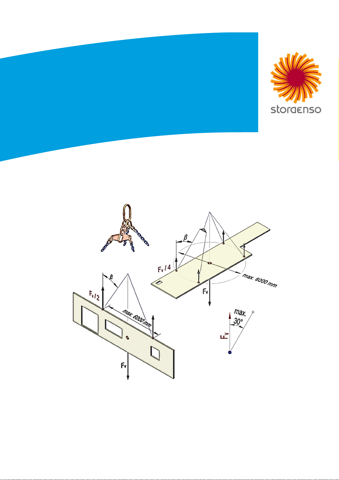
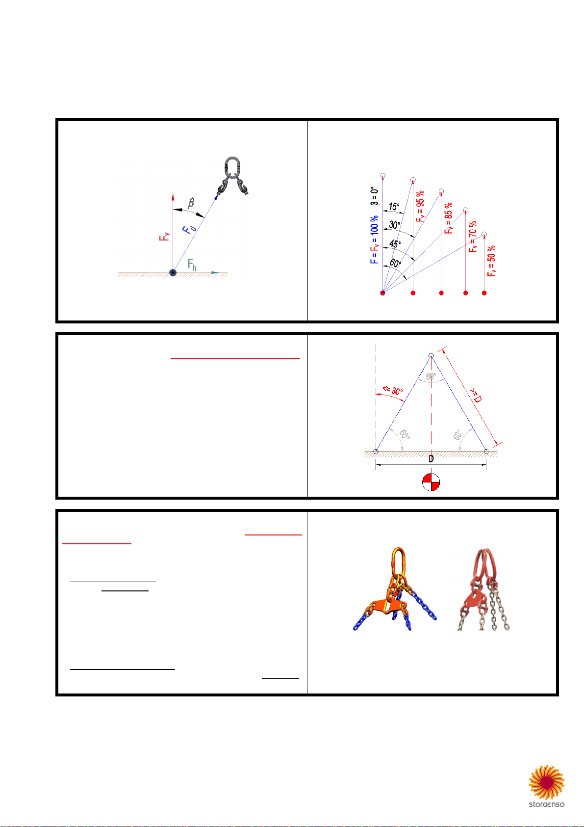
The lifting angle (β) has a significant influence on the load-bearing
capacity of each lifting system:
F
v
L
oad
>
vertical
share
F
d
Load
>
diagonal share
(chain/
anchor/sling
)
F
h
Lo
ad
>
horizontal
share
An increase of the lifting angle decreases the load-bearing capacity
(F
v
) of a lifting system, as you can see in the force diagram below:
If Stora Enso has to plan number and position of lifting points,
we have to assume that the lifting angle is not higher than 30°.
Required exceptions have to be verified and formally agreed:
•Higher lifting angles increase the risk and load-bearing capacity of
lifting devices is reduced. In any case lifting angles higher than
45° are not supported by Stora Enso.
•There is a simple rough-and-ready rule to secure that 30° in
practice is not exceeded: Chain length has to be equal or ideally
longer than the maximal distance between lifting points (D).
•The lifting points have to be aligned symmetrically regarding
center of gravity and lifting direction. Deviations are allowed if load
per lifting point is not increased more than 10 %.
If Stora Enso has to plan number and position of lifting points,
we have to assume a symmetric system and that all lifting points
are loaded equally. Required exceptions have to be verified and
agreements have to be formally confirmed.
Load distribution
If no load distribution gear is used, load-bearing capacity has to be
reduced at least by 25 %.
Symmetry
If lifting points regarding …
•chain lengths
•lifting angles
•center of gravity
…cannot be lifted symmetrically, then the load-bearing capacity has
to be verified by an expert and on demand to be reduced up to 50 %.
Examples: “balancing rocker”. It is an affordable and
very effective load distribution
gear
for
floor panels
.

4 (16) CLT Lifting Guideline
4-leg gear with a load distributor:
(examples)
Each lifting point is loaded equally with 1/4 of the total load if
center of gravity and lifting points are lifted symmetrically.
In other cases, load-bearing capacity has to be reduced at
least
by
25
%.
4-leg gear without a load distributor:
(example)
* Despite symmetrical alignment the total load is not
distributed equally to all 4 lifting points. Therefore load-
bearing capacity has to be reduced at least by 25 %.
This can be reasoned because not always each chain has
exactly the same length and because there are also always
small distance
respectively
symmetry deviations.
3-leg gear:
There are two conditions to distribute the total load equally to all
3 lifting points:
•All lifting points must have the same distance from center of
gravity.
•The angle between lifting points must be always 120°.
The lifting points are aligned within a relatively small area.
Having long panels this will cause higher deflection during
lifting. Therefore, three lifting points are only useful for quadratic
or small panels.
Wall panels are delivered in most cases horizontally. To upright such panels it has to be checked whether the load-bearing capacity of the
selected
lifting device works in both directions.
5 (16) CLT Lifting Guideline
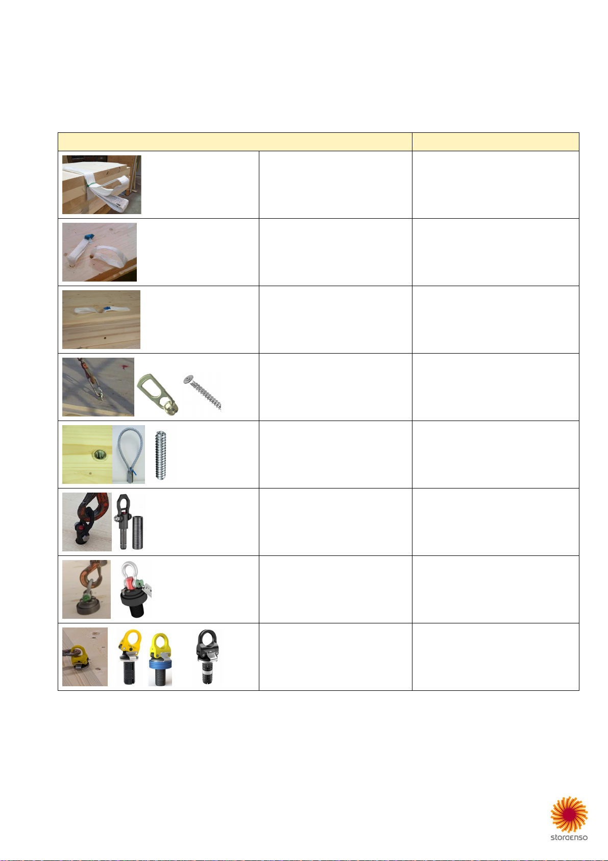
Overview lifting devices
The lifting of CLT panels is a very important and responsible topic to be considered in the early planning phase. There are different lifting devices
supported by Stora Enso, but not all can be used because of different national and/or own safety standards. It is the responsibility of the customer
to verify the lifting devices that are permitted for their projects.
Panel thickness, surface quality, building part type, mode of loading and most of all the load-bearing capacity (WLL = Working Load Limit) are
also important criteria that influence the choice of the proper lifting device.
Lifting
Device
B
uilding
P
art
T
ype
Lifting sling - one hole Wall: installed
Lifting sling - two holes Floor: installed
Lifting sling with blind-hole and dowel Floor: installed
Lifting screw with anchor Floor: not installed; blind-hole on demand
Wall: not installed; blind-hole on request
RAMPA insert and lifting loop Floor: installed
RAMPA Lifting:
•ball-lock pin
•insert type-X
Floor: installed
Sihga Pick – blind-hole Floor
Wall: on request
Power Clamp – blind-hole Floor
Wall: on request
6 (16) CLT Lifting Guideline
Lifting sling – one hole
Wall
EC
–
declaration of conformit
y:
P
lease see
Appendix.
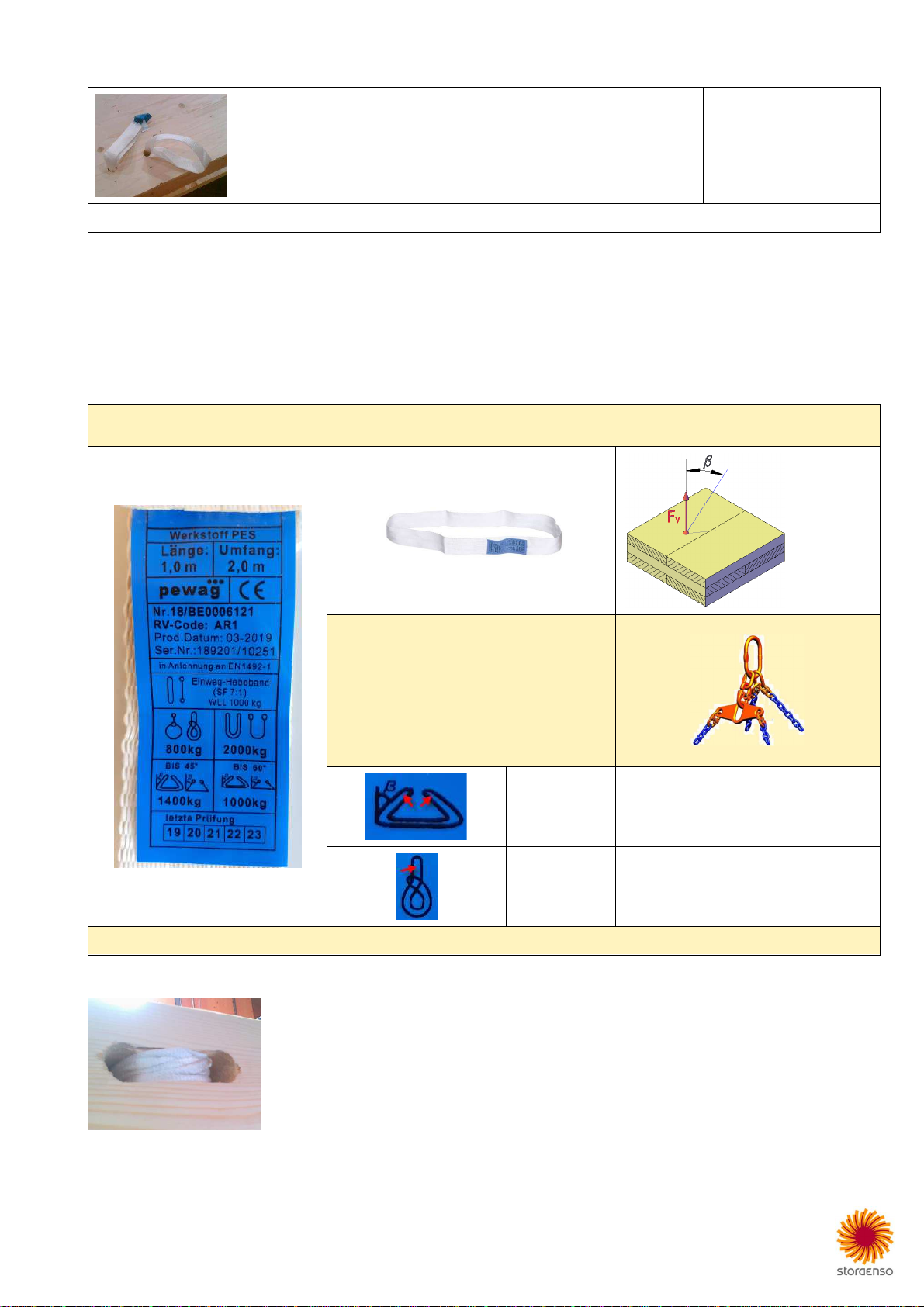
This lifting device is based on a webbing sling made of 100 % Polyester (PES). Standard length is 1 meter, width is 50 mm and thickness is
about 3 mm. On request special lengths like 2 or 4 meters are available.
The sling is installed in a hole with D35 mm and it is for single-use only. “Single-use” means maximal 6 lifting cycles with the same panel. It is
not allowed to remove slings to use them for other panels.
All slings must always be checked for damages before each lifting cycle.
The standard lifting method must be “Basket”. The sling is pre-mounted and delivered this way by Stora Enso and it is not allowed to
choke afterwards. On demand exceptions are possible. But this must be clarified with Stora Enso and finally formally confirmed.
The lifting angle (β) is assumed to be maximal 30°.
Indicated loads are only valid for hoisting velocity up to 36 m/min = 0.6 m/s.
≤30°
Lifting
Method
F
v
(kg)
“Basket”
(standard) 1000 (1400) *
“Choked”
(on request) 400 (560) *
*
As an exception
to be formally confirmed,
values in brackets can be
used.
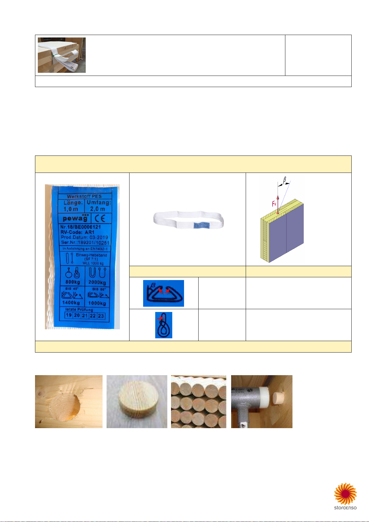
The drilling diameter is 35 mm. Depending on the load, the sling can cause localised crushing of the timber around the hole. The lifting hole can
be plugged when lifting is complete, using D35x10 mm timber plugs, or D35x1000 mm wooden poles that can be delivered:
7 (16) CLT Lifting Guideline
Lifting sling – two holes
Floor
EC
–
declaration of conformity
:
P
lease se
e Appendix.
This system is based on a webbing sling made of 100 % Polyester (PES). Standard length is 1 meter, width is 50 mm and thickness is about 3
mm. On demand special lengths like 2 or 4 meters are available.
The sling is installed in two holes with D35 mm and it is for single-use only. “Single-use” means maximal 6 lifting cycles with the same panel, but
you are not allowed to remove slings to use them for other panels.
All slings must always be checked for damages before each lift.
The standard lifting method must be “Basket”. The sling is pre-mounted and delivered this way by Stora Enso and it is not allowed to
choke afterwards. On demand exceptions are possible. But this must be clarified with Stora Enso and finally formally confirmed.
The lifting angle (β) is assumed to be maximal 30°.
Indicated loads are only valid for
hoisting velocity up to 36 m/min = 0.6 m/s.
≤30°
Lifting Method
with load distributor *
F
v
(kg)
“Basket”
(standard) 1400
“Choked”
(on request) 560
*
Without
load distributor
(
or something
equivalent
)
indicated loads have to be
reduced
at least
by
25 %.
The drilling diameter is 35 mm. Depending on the load, slings can cause localized crushing of the timber:

8 (16) CLT Lifting Guideline
Lifting sling – with blind-hole and dowel
Floor
EC
–
declaration of conformity
Please see
Appendix.
Expert Opinion No. GU20-403-3-01 Graz University of Technology
Lignum Test Center (LTC)
The webbing sling is made of 100 % Polyester (PES). Standard length is 1 meter, width is 50 mm and thickness is about 3 mm. On demand
special lengths like 2 or 4 meters are available.
The sling is installed in a blind-hole with D68 mm and it is for single-use only. “Single-use” means maximal 6 lifting cycles with the same panel,
but you are not allowed to remove slings to use for other panels.
The sling is fixed by a steel dowel and is stuffed into the blind-hole for easy stacking and transport.
All slings must always be checked for damages before each lift.
The standard lifting method must be “Basket”. The sling is pre-mounted and delivered this way by Stora Enso and it is not allowed to
choke afterwards. On demand exceptions are possible. But this must be clarified with Stora Enso and finally formally confirmed.
The lifting angle (β) is assumed to be maximal 30°.
Indicated loads are only valid for hoisting velocity up to 36 m/min = 0.6 m/s.
≤30°
Lifting Method
with load distributor *
“Basket”
(standard)
CLT (mm) F
v
(kg)
80 - 90 500
100 - 150
1000
> 150 1250
“Choked”
(on request) max. 560
“Inline”
(on request) max. 700
* Without
load distributor
(
or something
equivalent
)
indicated loads
have
to be reduced
at least
by
25 %.

9 (16) CLT Lifting Guideline
Below parameters for drillings and load-bearing capacities of our standard CLT panels styles. If a panel style is not listed, then parameters for
blind-hole and steel dowel must be done according to the following basic two rules:
•t1 … The blind-hole should be as deep as possible but can be maximal 160 mm.
•t2 … The steel dowel has to be 20 mm less deep than t1 and dowel axis should be aligned perpendicular under the layer above.
Steel dowel (d):
•diameter: 16 mm
•length: 300 mm
•depth (t2): see table below
•steel grade: S235
Blind-hole (D):
•diameter 68 mm
•depth (t1): see table below; max. 160 mm
Edge distance (y):
•min = 200 mm
•max = 340 mm
Webbing PES sling: 50x1000 mm; blue label
The lifting angle (β) is assumed to be maximal 30°.
Indicated loads are only valid for hoisting velocity up to 36 m/min = 0.6 m/s.
Product
Thickness
Structure
Blind-hole
t1
Steel dowel
t2
with load
distributor *
F
v
(kg)
CLT
60
L3s
not
possible
CLT
80
L3s
70
50
500
CLT
90
L3s
80
60
500
CLT
100
L3s
90
70
1000
CLT
120
L3s
110
90
1000
CLT
100
L5s
90
70
1000
CLT
120
L5s
100
80
1000
CLT
140
L5s
110
90
1000
CLT
160
L5s
130
110
1250
CLT
180
L5s
140
120
1250
CLT
200
L5s
-
2
150
130
1250
CLT
160
L5s
-
2
140
120
1250
CLT
180
L7s
160
140
1250
CLT
200
L5s
160
140
1250
CLT
240
L7s
160
140
1250
CLT
220
L7s
-
2
160
140
1250
CLT
240
L7s
-
2
160
140
1250
CLT
260
L7s
-
2
160
140
1250
CLT
280
L7s
-
2
150
130
1250
CLT
300
L8s
-
2
160
140
1250
CLT
320
L8s
-
2
160
140
1250
*
With
out
load distributor
(
or something
equivalent
)
indicated loads have to be reduced
at least
by
25 %.
10 (16) CLT Lifting Guideline
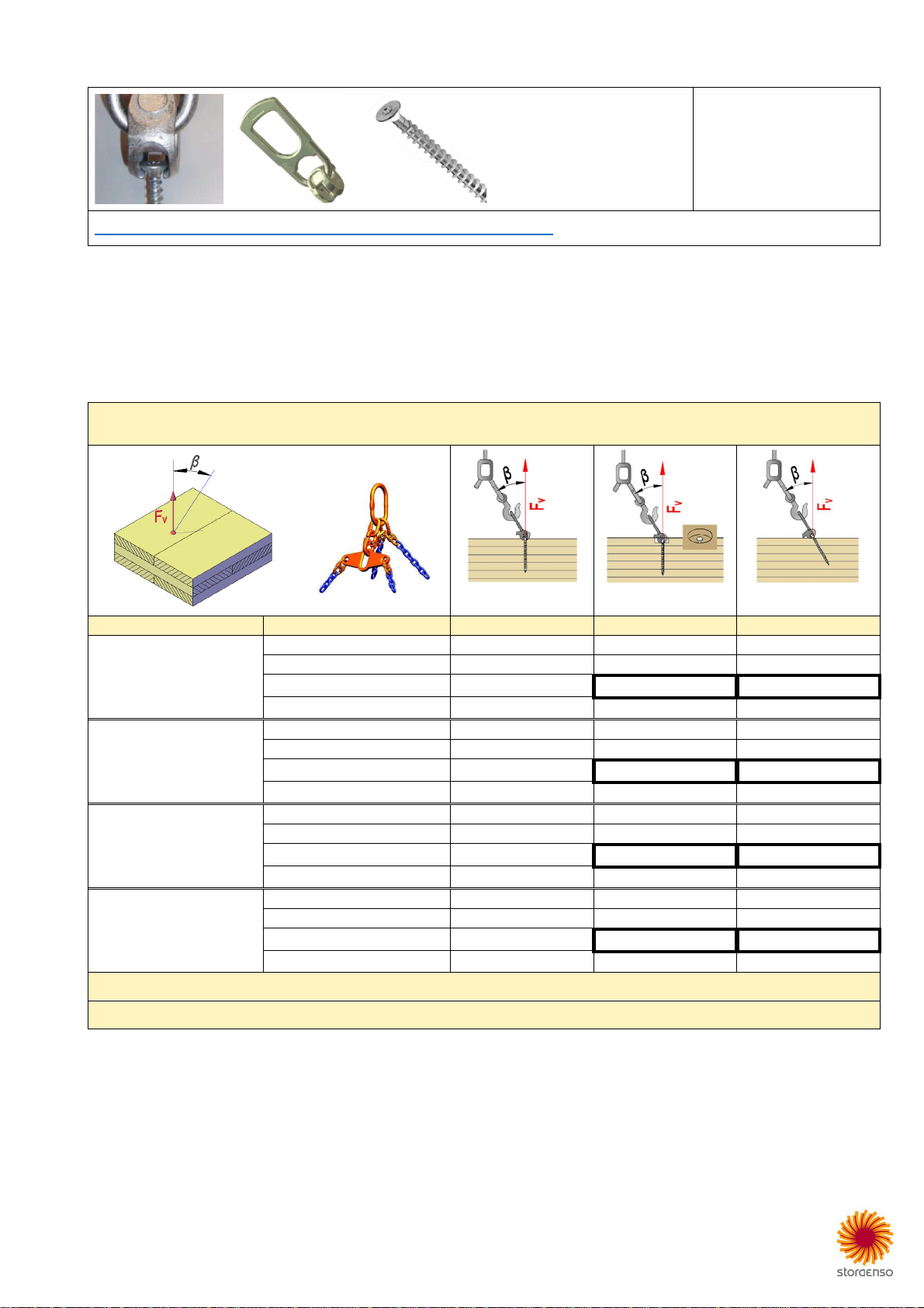
Lifting screw with anchor
Floor
Wall
https://www.rothoblaas.com/products/machines-and-tools/transport-and-lifting/wasp
Use must be done according to the original instructions for use (technical data sheets). To always get the latest documents, we ask you to visit
the homepage of supplier and/or contact their technical support. Please inform Stora Enso if here indicated links do not work correctly or if there
is a relevant discrepancy with summarized info below.
This lifting system is not installed by Stora Enso. On demand we can deliver required material (anchors and screws).
Floor
On demand lifting device location mark drillings D10x10 mm (small drill hole) or blind-holes D55x30 mm (large drill hole) can be done to allow
accurate positioning of lifting screws on site:
The lifting angle (β) is assumed to be maximal 30°.
Indicated loads are only valid for
hoisting velocity up to 36 m/min = 0.6 m/s.
with load distributor *
perpendicular **
perpendicular
with
blind
-
hole
inclined
Screw
…
β
(
°
)
F
v
(kg)
***
F
v
(kg)
F
v
(kg)
VGS Ø11
100
0
430
430
430
15
350
430
410
30
240
430
370
45
150
430
300
VGS Ø11
150
0
710
710
710
15
570
710
690
30
380
710
620
45
240
450
500
VGS Ø11
200
0
1000
1000
100
0
15
760
980
970
30
470
780
870
45
290
450
710
VGS Ø11
250
0
10
10
1010
1010
15
860
980
980
30
500
780
880
45
300
450
720
* Without
load distributor
(
or something
equivalent
)
indicated loads have to be reduced
at least
by
25 %.
**
Not recommended.

11 (16) CLT Lifting Guideline
Wall
On request lifting device location marks D10x10 mm (small drill hole) or blind-holes D55x30 mm (large drill hole) can be done to allow accurate
positioning of lifting screws on site:
The lifting angle (β) is assumed to be maximal 30°.
Indicated loads are only valid for hoisting velocity up to 36 m/min = 0.6 m/s.
perpendicular *
perpendicular
with blind-hole
inclined
Screw
…
β
(
°
)
F
v
(kg)
F
v
(kg)
F
v
(kg)
VGS Ø11
200
0
630
630
630
15
420
630
610
30
240
630
550
45
150
450
440
VGS Ø11
250
0
790
790
790
15
530
790
770
30
300
780
690
45
180
450
560
s Please note that screws may not be inserted parallel to grain direction.
T
hickness of concerned layer
can be 20, 30 or 40 mm.
*
Not recommended.

12 (16) CLT Lifting Guideline
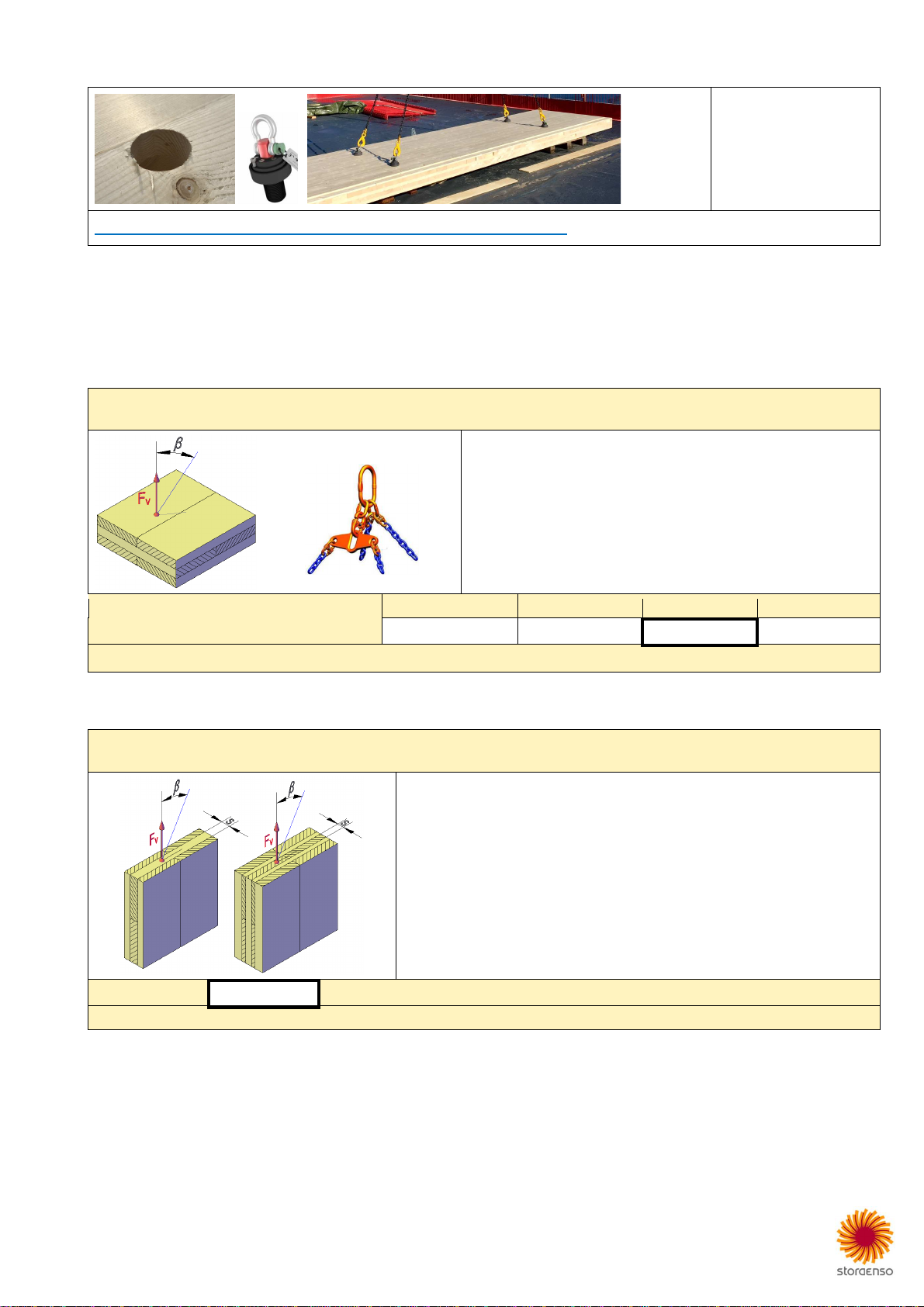
RAMPA insert with lifting loop
Floor
https://www.rampa.com/service/wp
-
content/uploads/2021/03/RAMPA_Lasttabelle_BL
-
SKL
-
D25M16
-
2021.pdf
Use must be done according to the original instructions for use (technical data sheets). To always get the latest documents, we ask you to visit
the homepage of supplier and/or contact their technical support. Please inform Stora Enso if here indicated links do not work correctly or if there
is a relevant discrepancy with summarized info below.
The insert is installed and on demand required lifting loops can be delivered.
The lifting angle (β) is assumed to be maximal 30°.
Indicated loads are only
valid for hoisting velocity up to 36 m/min = 0.6 m/s.
with load distributor *
Minimal panel thickness: 60 mm
Blind-hole: D22x45/65/85/105 mm
RAMPA-Insert Type …
F
v
(
β)
kg (0°) ** kg (30°)
BL
D25 x 40 mm
330
290
BL/SKL
D25 x
60 mm
475
410
BL/SKL
D25 x
80 mm
640
550
BL/SKL
D25 x
100 mm
810
700
* Without
load distributor (or something equivalent)
indicated loads have to be reduced
at least
by
25 %.

13 (16) CLT Lifting Guideline
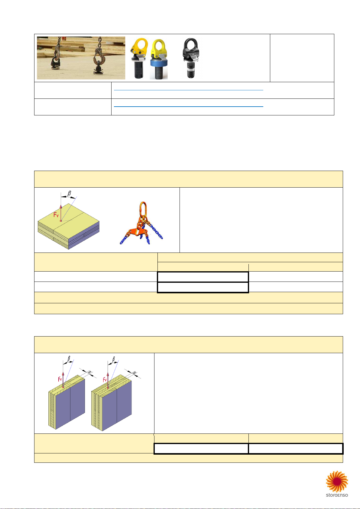
RAMPA lifting gear
Floor
https://www.rampa.com/service/en/products/wood-applications/lifting_gear/
Use must be done according to the original instructions for use (technical data sheets). To always get the latest documents, we ask you to visit
the homepage of supplier and/or contact their technical support. Please inform Stora Enso if here indicated links do work correctly or if there is a
relevant discrepancy with summarized info below.
Regarding insert type-X is installed and on demand ball-lock anchor (load suspension type-X) can be delivered.
The lifting angle (β) is assumed to be maximal 30°.
Indicated loads are only valid for hoisting velocity up to 36 m/min = 0.6 m/s.
with load distributor *
Minimal panel thickness: 80 mm
Blind-hole: D34x75 mm
RAMPA-Insert: Type-X D36x73 mm
β
0°
30°
45°
60°
**
F
v
(kg)
900
770
620
440
* Without
load distributor (or something equivalent)
indicated loads have to be reduced
at least
by
2
5 %.
**
Not recommended
.
14 (16) CLT Lifting Guideline
Sihga Pick
Floor
Wall (on request)
https://www.sihga.com/ecommerce/product?category_id=153948&product_id=546961
Use must be done according to the original instructions for use (technical data sheets). To always get the latest documents, we ask you to visit
the homepage of supplier and/or contact their technical support. Please inform Stora Enso if here indicated links do not work correctly or if there
is a relevant discrepancy with summarized info below.
Stora Enso does not sell this product but we can produce the required drillings under the following conditions:
Floor
Number and position of lifting points can be planned by Stora Enso:
The lifting angle (β) is assumed to be maximal 30°.
Indicated loads are only valid for hoisting velocity up to 36 m/min = 0.6 m/s.
with load distributor *
Minimal panel thickness: 80 mm
Blind-hole:
•D50x75 mm
•Tolerance diameter: -0.0 / +1.0 mm.
•Edge distance: 250 mm
β
(mini
mal
= 5°)
5°
15°
30°
45°
F
v
(kg)
**
1100
1000
900
800
* Without
load distributor (or something equivalent)
indicated loads have to be reduced
at least
by
25 %.
Wall (on request)
On request number and position of lifting points can be planned by Stora Enso:
The lifting angle (β) is assumed to be maximal 30°.
Indicated loads are only valid for hoisting velocity up to 36 m/min = 0.6 m/s.
Minimal panel thickness: 90 mm
Minimal edge distance: 20 mm
Blind-hole:
•D50x75 mm
•Tolerance diameter: -0.0 / +1.0 mm
Please consider that the blind-hole may not be positioned parallel to grain direction
within a zone where the end grain share is more than 40 mm.
F
v
(kg)
*
260
More d
etails according to original instructions for use (technical data sheet).
* Indicated load
s
are only valid for hoisting velocity up to 36 m/min = 0.6 m/s.
15 (16) CLT Lifting Guideline
Power Clamp
Floor
Wall (on request)
PowerClamp III D40x90(70*) https://www.pitzl-connectors.com/en/products/product-list/55890.1000
* 70 mm
:
with
spacer ring (blue)
PowerClamp II D40x90 https://www.pitzl-connectors.com/en/products/product-list/55860.1000
N
o longer available
, but still in use. Replaced by Power
Clamp III
D
40
x
90
.
Use must be done according to the original instructions for use (technical data sheets). To always get the latest documents, we ask you to visit
the homepage of supplier and/or contact their technical support. Please inform Stora Enso if indicated links do not work correctly or if there is a
relevant discrepancy with basic info below.
Stora Enso does not sell this product but we can produce the required drillings under the following conditions:
Floor
Number and position of lifting points can be planned by Stora Enso:
The lifting angle (β) is assumed to be maximal 30°.
Indicated loads are only valid for hoisting velocity up to 36 m/min = 0.6 m/s.
with load distributor *
Minimal panel thickness:
•100 mm – Standard
•80 mm – with spacer ring
Blind-hole:
•D40x95 mm – standard
•D40x75 mm – with spacer ring
•Tolerance diameter: -0.0 / +1.0 mm
•Edge distance: 200 mm
PowerClamp …
F
v
(
β)
kg
(
0°
-
45°)
***
kg
(
45°
-
60°
)
**
III D40/90
1050
750
II D40/90
700
525
* Without
load distributor (or something similar)
indicated loads have to be reduced
at least
by
25 %.
**
Not recommended by Stora
E
nso.
Wall (on request)
On request number and position of lifting points can be planned by Stora Enso:
The lifting angle (β) is assumed to be maximal 30°.
Indicated loads are only valid for hoisting velocity up to 36 m/min = 0.6 m/s.
Panel thickness:
•minimal: 80 mm
•edge distance: 20 mm
Use of spacer ring is not allowed for walls.
Blind-hole:
•D40x95 mm
•Tolerance diameter: -0.0 / +1.0 mm
F
v
(kg)
PowerClamp III D40/90
PowerClamp II D40/90
525
350
More d
etails according to original instructions for use (technical data
sheet).

16 (16) CLT Lifting Guideline
Appendix
Table of contents
Popular Lifting System manuals by other brands


Tractel Group
Tractel Group scafor 408C Series Operating and maintenance instructions

HSS Hire
HSS Hire 70132/3 Operating & safety guide

morse
morse 520-114 Operator's manual

EZ-ACCESS
EZ-ACCESS PATHWAY Classic Series Instructions for use

Ravaglioli
Ravaglioli S1140A4 Translation of the original instructions

WITTUR
WITTUR WSG09 Operating and maintenance manual

Kelley
Kelley HK-S user manual

Haklift
Haklift VAK6 Translation of the original instructions

iCONNECT
iCONNECT TVL-RH installation instructions

Bravi Platforms
Bravi Platforms SPRINT LUI MINI T.L. Use and safety

Rotary
Rotary SM122-100 Series owner's manual

Harmar Mobility
Harmar Mobility AL100-DE owner's manual