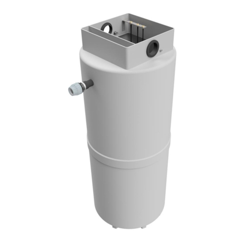
PREMIER TECH REWATEC PSA-240 Programming manual

Installation guide and Owner’s manual Page 1/10 20201029
Pumping stations PSA-240/H Item # 183036
Installation guide and Owner’s manual
Pumping stations PSA-240/H
This guide provides information regarding the installation, operation, maintenance and warranty of the PSA-240 and PSA-240H
Pumping Stations from Premier Tech. For additional information, contact our customer service at 1-800-632-6356.
1. Technical data
PSA-240: The effective volume of the pumping station’s reservoir is of 150 L (40 US gallons, 33 Imperial gallons). The pumping station
can therefore be used for a treatment system with up to three Ecoflo®biofilters or with any other type treatment system that does not
require a dose volume greater than 150 L.
PSA-240H: The effective volume of the pumping station’s reservoir is of 255 L (67 US gallons, 56 Imperial gallons). This pumping
station is normally used to feed low pressure distribution systems for sand filters and seepage beds when a dosing volume between
150 and 255 L is required.
Models PSA-240 PSA-240H
Material (reservoir and lid)
Polyethylene
Polyethylene
Pump
120 V (197073)
120 V (314982)
Float
On/Off pump switch and alarm switch
Double On/Off pump switch and alarm switch
Inlet height
635 mm (25")
1 060 mm (41¾")
Water inlet and aeration duct
Adapted for all types of pipe Ø 100 mm (4") nominal
Adapted for all types of pipe Ø 100 mm (4")
nominal
Outlet height
1 015 mm (40")
1 015 mm (40")
Outlet
Adapted for a flexible pipe Ø 38 mm (1.5") nominal
Adapted for a flexible pipe Ø 50 mm (2") nominal
Total volume (at water inlet level)
240 L
400 L
Effective dosing volume
150 L
255 L
Weight
50 kg (110 lb)
56 kg (123 lb)
Adaptor
Biofilter inlet included
—
Certification
The pump, the float and the alarm system are all CSA certified (Canadian Standards Association)
* Depends on the treatment system with which it is paired. The pumping station operates according to the principle of connecting vessels.

Installation guide and Owner’s manual Page 2/10 20201029
Pumping stations PSA-240/H Item # 183036
PSA-240 pumping station
PSA-240H pumping station
Barbed coupling
for water outlet pipe
50 mm Ø (2") nominal
Flexible coupling
for water inlet pipe
Ø 100 mm (4")
nominal
2. Dimensions, description and location
2.1 Dimensions
PLAN VIEW
PSA-240/L/H pumping station base
Barbed coupling
for water outlet pipe
Ø 38 mm (1½") nominal
Flexible coupling
for water inlet pipe
Ø 100 mm (4") nominal
622 mm (24 ½")
510 mm (20")
355 mm
(14")
PSR-140 riser

Installation guide and Owner’s manual Page 3/10 20201029
Pumping stations PSA-240/H Item # 183036
2.2 Description
The pumping stations are pre-assembled and include the following components:
A. Ball valve
B. Float tree
C. Alarm float
D. On/Off float
(1 for the PSA-240/L and 2 for the PSA-240H)
E. Submersible effluent pump
F. Cam coupler
G. Alarm box
H. Electrical junction box with waterproof screw-thread wire
connectors (not assembled)
I. Ecoflo biofilter inlet coupling and 100 mm – 38 mm (4" 1½") Ø
adaptor for model PSA-240
(not assembled)
J. 100 mm – 50 mm (4"– 2") Ø adaptor (PSA-240H)
(not assembled)
The pumping station water inlets are ready to be connected either to effluent pipe of a primary treatment unit (septic tank) for models
PSA-240 and PSA-240H.
2.3. Component location
The PSA-240 and PSA-240H pumping stations must always be installed after the septic tank or after the effluent filter container if such
is the case. They should never be used in raw water.
For minimum observable distances, refer to the regulations or standards that apply in your region, state, province or country.
A
B
C
D
G
H
I
E
F
PSA-240
D
PSA-240H
PSR-140 riser
PSA-240 pumping station before a soil absorption field
PSA-240 pumping station before an Ecoflo biofilter
Septic
tank
PSA-240H pumping station before a soil absorption field
Septic tank
PSA-240H
Pumping Station
Effluent
filter
Soil absorption field with a low pressure distribution system
Septic
tank
PSA-240
Pumping Station
PSA-240
Pumping Station
Water feeding pipe
Ø 38 mm (1½") Water feeding pipe
Ø 38 mm (1½")
ST-500/650
Ecoflo
®
Biofilter
Soil absorption field
Aeration duct Ø 100 mm (4")
Inlet adaptor
Septic
tank

Installation guide and Owner’s manual Page 4/10 20201029
Pumping stations PSA-240/H Item # 183036
3. Location, installation and operation guidelines
It is very important to advise everyone involved (installer, landscaper, owner, snow removal service, etc.) of the
following guidelines:
•Respect the minimum distances prescribed by regulations.
•Never install a pumping station in a place where the groundwater table can reach its base (otherwise, drain pipes could be required).
•The profile of the lot must be such that surface run off flows away from the pumping station.
•Never install a pumping station in clayey soil.
•The pumping station must be installed as close as possible to the septic tank (PSA-240/H) or to the treatment system upstream
(PSA-240L) to minimise the depth at which it must be installed.
•A maximum of two (2) PSR-140 (355 mm, 14") Premier Tech risers can be installed on the PSA pumping stations. The
maximum allowable riser height is of 710 mm (28"). IMPORTANT: take note that the PSA-240H pumping station is already
equipped with one (1) PSR-140 riser, therefore, it is only possible to install one (1) additional PSR-140 riser.
•The house must be equipped with an air vent that is in proper working order and that complies with the applicable standards.
•For transporation purposes, it is preferable that the pumping station be in the vertical position, however, if it is not possible and the
pumping station must be laid on its side, please proceed with precaution and make sure all the components are not damaged
during transportation.
•Ensure rapid growth of vegetation to prevent soil erosion.
•The pumping station must be accessible at all times, do not cover the lid. The lid must be at least 50 mm (2") above the surface of
the landscaped lot.
•The pumping station must be watertight and must not receive any infiltration water and should only receive the wastewater
treatment process.
•Never connect a drain pipe, roof gutter, sump pump or air conditioning drain to your septic system.
•Never discharge water from a water softener backwash in your septic system.
•Never use an automatic bowl cleaner.
•Never overload the soil (ex: blown snow, embankment/slope) within 3 m (10') of the lid. The overload could damage the pumping
station.
•Never drive vehicles or place objects weighing over 225 kg (500 lbs) within 3 m (10') of the pumping station’s lid.
•Never plant trees within 2 m (6'5") of the pumping station’s lid.
•Never open or go inside the pumping station without prior authorisation.
•No object must be thrown or dropped inside the pumping station.
•The discharge of any objects or substances into the septic tank that might clog the pumping station is proscribed. Using an effluent
filter at the septic tank’s effluent is therefore strongly recommended in order to protect the pump and avoid any clogging or
breakage.
It is not recommended to discharge any of the following substances into the system:
•Oil and grease (motor oil, cooking oil, etc.);
•Wax and resins;
•Paints and solvents;
•Any kind of petroleum product;
•Any kind of pesticide;
•Any kind of septic tank additive;
•Any kind of toxic substance;
•Anything not easily biodegradable (for example, coffee beans, cigarette butts, sanitary napkins,
tampons, condoms, cotton swab, etc.).

Installation guide and Owner’s manual Page 5/10 20201029
Pumping stations PSA-240/H Item # 183036
4. Installation steps
STEP 1 – Excavating, bedding preparation and placing of the pumping station
•Excavate the required area by respecting the minimum distances shown
on the adjacent illustration.
•Level and compact the bedding material (H2) which consists of Ø 0-20
mm (0-¾") gravel or sand.
•Place the pumping station on a level and stable layer of fine gravel.
•The pumping station must be accessible at all times and must be 50 mm
(2") above the surface of the landscaped lot.
•A maximum of two (2) PSR-140 risers is allowed.
STEP 2 – Pipe connections
PSA-240 and PSA-240H pumping stations:
•Connect the septic tank or other equipment to the pumping station using a pipe that complies with the regulations. Relier la fosse
septique au poste de pompage avec une conduite conforme aux normes applicables. The pipe must have a minimum downward
slope of 2% towards the pumping station.
•Connect the pumping station to the inlet pipe of the Ecoflo biofilter or to the required treatment system using either a flexible 38 mm
(1½") Ø pipe for the PSA-240 or a flexible 50 mm (2") Ø pipe for the PSA-240H that can withstand at least 700 kPa (100 PSI) of
pressure and is suitable for underground applications.
•In the case of an Ecoflo biofilter installation, run a rigid 100 mm (4") Ø ventilation pipe between the pumping station and the biofilter.
A 100 mm - 38 mm (4" - 1½") Ø adaptor (Item I identified in section 2.2) is provided to complete the connection. This adaptor must
be glued at ± 45º from the horizontal, depending on the angle at which it is easiest to install. Important: always connect the 38 mm
(1½") Ø pipe under the 100 mm - 38 mm (4" - 1½") Ø adaptor to break the pump’s flow before the eflluent penetrates the
biofilter. (Refer to the illustration PSA-240 pumping station before an Ecoflo biofilter in section 2.3).
•If the distance between the pumping station and the biofilter is greater than 20 m (70'), it is preferable to equip the biofilter with its
own ventilation duct instead of connecting the duct to the pumping station.
•The pipes must be installed in a way that they drain by gravity.
•Precautionary measures against freezing must be taken in order to protect the pipe connecting the pumping station to the treatment
system.
STEP 3 – Riser installation (if required)
When the pumping station installation requires extension risers, proceed as
follows:
•Use PSR-060 (150 mm, 6") risers or PSR-140 (355 mm, 14") risers if required.
Maximum height of risers: 710 mm (28").
•Clean the access rim of the pumping station (where 4 holes were perforated to
insert the lag screws).
•Install the watertight seal on the pumping station’s access rim.
•Align the holes of the riser with the holes of the pumping station.
•Insert the washers in the lag screws provided with the riser and screw them in
place to firmly fix the riser.
STEP 4 – Electrical connections
The electrical connections should be executed by an electrician. IF YOUR LOCAL ELECTRIC CODE ALLOWS IT, remove the
connector plugs from the float and pump wires by cutting the ends and perform the electrical connections using the supplied
waterproof screw-thread wire connectors in order to ensure the water does not affect the electrical circuit. The use of waterproof
screw-thread wire connectors is mandatory with the electrical junction box. Note that the junction box must be installed outside of the
pumping station, on a post above the ground surface, to prevent the box from being submerged and also to have access to the box at
all times.
PSR-060 riser 150 mm (6") or
PSR-140 riser 355 mm (14")
4 stainless steel 304 lag screws
with 4 plastic washers
Watertight seal
Pumping station

Installation guide and Owner’s manual Page 6/10 20201029
Pumping stations PSA-240/H Item # 183036
To wire the system, two (2) in-ground double strand supply cables are required. It is preferable to protect the wires with the
appropriate piping before burying them. To pass wires through the pumping station’s wall, use watertight bulkhead union fittings.
Note: Two independant circuit-breakers must be used to connect the pump and the alarm box. Each circuit must have an
independent breaker of sufficient intensity equipped with a ground wire protection.
Important: before the pumping station start-up, check if the float holding device for the transportation has been removed. Also
check if the floats are ready and in the proper position for operation.
STEP 5 – Final backfill
•Close the lid so nothing falls into the pumping station during backfill.
•Isolate the pipes if required.
•Backfill the pumping station and the pipes with material void of any organic
matter, impervious soil, stones, debris, particles larger the 20 mm (¾") in
diameter or any other object that could damage the pumping station.
•The backfill material must be placed with care and not dumped (do not
compact with bulldozer).
•Allow space for ground cover and make sure the lids are at least 50 mm (2") above the surface of the landscaped lot.
•Finalise the backfill with a layer of soil that encourages vegetation growth.
STEP 6 - Alarm box installation
The pumping station is equipped with a high-water-level float connected to an alarm system. This alarm
system must be installed inside the residence (home) so it can be heard when it is activated. The following
information describes how the system works.
A red indicator lights up when the water level in the Ecoflo biofilter is unusually high. If an alarm is
activated, contact Premier Tech's After-Sales Service Department because the incident has to be
checked. To silence the alarm, press the “SILENCE” button.
The “TEST” button lets you check if the alarm system is working properly. During a test, the red indicator
should light up and an audio alarm should be heard.
In the event of a power failure, the alarm system continues to function on an emergency 9-volt alkaline battery (not supplied). Using a
rechargeable battery is not recommended.
NOTE: Replace the emergency battery every 12 months, each time the alarm is activated or whenever there is a power failure. If
the battery is weak, the system will beep once every minute. When this occurs, replace the battery immediately.
PSA-240 and PSA-240L
Wiring diagram
Wrap black electrical tape
around the white wire of the
On/Off float
White
Alarm box wire
Alarm
float
Pump
On/Off
float
120 VAC power
cable
Black
White
Black
White
Green - ground
Ground
Green - ground
White
Black – L1
Black
PSA-240H
Wiring diagram
Double
Alarm box wire
Alarm
float
Pump
Double
On/Off
float
120 VAC
power cable
Black
Black
White
White
Green - ground
Green - ground
Ground
Red
Black – L1
Black
White
PSR-060 or PSR-140
riser (if required)
Maximum 91 cm (36")
Alarm box for pumping
station

Installation guide and Owner’s manual Page 7/10 20201029
Pumping stations PSA-240/H Item # 183036
To replace the 9-volt battery:
•Disconnect the alarm box and remove it from the wall (the battery is inserted on the side of the box).
•Open the cover of the 9-volt battery compartment and replace the battery with a 9-volt alkaline battery.
•Close the cover, reinstall the box on the wall and reconnect it.
•If the alarm is activated, press the “RESET/TEST” button to initialize it.
5. Pumps performance curves
The figure below presents the performance curves of the different pumps used in the pumping stations.
Note that these curves were obtained with clear water, the pumps might not perform as well with wastewater. If you have questions
about the interpretation of these curves, please do not hesitate to contact Premier Tech.
6. Pumping station start-up and adjustment
6.1 For all the pumping stations
Take the pump out of the pumping station by previously removing the fastener that ties it to the reservoir (do not leave the fastener in
the pumping station) and perform a visual inspection. Then, place the pump in the reservoir and connect the water outlet pipe using
the cam coupler. Take the float tree out of the pumping station. Remove the fastener holding the floats for transportation purposes
(do not leave the fastener in the pumping station). Make sure the floats are properly attached to the float tree and adjusted as
specified in the following sections. Then, attach the float tree to the pumping station by placing the lower end in the cavity found at the
bottom of the reservoir and attach the upper end to the fastener on the side wall of the pumping station.
What you must know for all the pumping stations:
•Make sure the bottom of the pumping station is clean and void of any objects that could
damage the pumping station.
•Adjust the cable’s length on the On/Off float to obtain the wanted dosage for your
application.
•The minimum water level in the pumping station is of 185 mm (7¼").
The following sections address the different start-up and adjustment specifications according to the different pumping stations.
≥185 mm
(7¼")

Installation guide and Owner’s manual Page 8/10 20201029
Pumping stations PSA-240/H Item # 183036
6.2 PSA-240 Pumping station
The following table specifies the cable’s recommended length (L) of the On/Off
float for a maximum distance of 48 m (160') between the pumping station and
the treatment system. It presents different values for 1 and 2 Ecoflo biofilters
(or a dose of approximately 50 L and 100 L for other treatment systems).
Number
biofilter
(dose)
Pipe Ø
nominal
Length of the pipe between the pumping station and the treatment system
6 m (20')
12 m (40')
18 m (60')
24 m (80')
30 m (100')
36 m (120')
42 m (140')
48 m (160')
Length the On/Off float cable (presented by 'L' on the illustration above)
1
(50 L)
25 mm (1")
100 mm (4")
100 mm (4")
100 mm (4")
125 mm (5")
125 mm (5")
125 mm (5")
125 mm (5")
150 mm (6")
31 mm (1¼")
100 mm (4")
100 mm (4")
100 mm (4")
125 mm (5")
150 mm (6")
175 mm (7")
200 mm (8")**
200 mm (8")**
38 mm (1½")
100 mm (4")*
100 mm (4")*
125 mm (5")
150 mm (6")
175 mm (7")
200 mm (8")**
225 mm (9")**
250 mm (10")**
50 mm (2")
100 mm (4")
125 mm (5")
175 mm (7")
225 mm (9")**
na
na
na
na
2
(100 L)
25 mm (1")
175 mm (7")
175 mm (7")
200 mm (8")**
200 mm (8")**
200 mm (8")**
225 mm (9")**
225 mm (9")**
250 mm (10")**
31 mm (1¼")
175 mm (7")
200 mm (8")**
200 mm (8")**
225 mm (9")**
250 mm 10")**
250 mm (10")**
na
na
38 mm (1½")
175 mm (7")
200 mm (8")**
225 mm (9")**
250 mm (10")**
na
na
na
na
50 mm (2")
200 mm (8")**
250 mm (10")**
na
na
na
na
na
na
*The length of the cable is pre-set to that length at the plant.
**The alarm float has to be moved 50 mm higher than its initial position on the float tree. The length of the cable must remain at 3" (75 mm).
Finally, adjust the valve so that water flows into the Ecoflo biofilter at an acceptable rate and the dosage time for each hydraulic event
(40 L, 8.8 imp. gallons, 10 US gallons) is at least 30 seconds. To check if the dosage is appropriate, the tipping bucket should fill-up a
maximum of 12 times per hydraulic event.
6.4 PSA-240H Pumping station
The following table specifies the required distance between the On/Off floats (H) according to the dosage required for the treatment
system.
Required dose Distance between floats (H) Length of the On/Off float cable
(L)
50 L
17 cm
L is pre-set at 100 mm (4") at the plant
100 L
34 cm
150 L 51 cm
200 L
69 cm
250 L
86 cm
7. Maintenance
The pumping station has mechanical components, therefore, it is preferable to conduct an annual preventive inspection. Furthermore,
it is important to comply with the regulations regarding the septic tank emptying in order to prevent large particles from escaping the
septic tank and blocking the pump. We strongly recommend you empty your pumping station at the same time as your septic tank.
On/Off float
**See note
Alarm
float
75 mm (3")

Installation guide and Owner’s manual Page 9/10 20201029
Pumping stations PSA-240/H Item # 183036
8. What to do in case of...
8.1 An activated alarm
If an alarm is activated in your pumping station, unrelated to a power failure, contact Premier Tech’s After-Sales Service Department so
the problem can be identified and corrected.
8.2 A prolonged power failure
If a power failure that occurs during winter is prolonged, protect the components of your septic system against freezing. If you have
any questions to restart your pumping station, contact Premier Tech’s After-Sales Service Department.
8.3 Flooding
Certain sites are prone to flooding or to rises in groundwater levels. This can lead to a malfunction in your septic pumping station. If this
happens, contact Premier Tech's After-Sales Service Department.
8.4 Backflow
Backflow rarely occurs. But if it does happen, the septic tank is usually the cause. Your septic tank installer or septic tank pumper can
generally take care of the situation.
8.5 Odours
The position of the air vent, as well as other factors unrelated to the pumping station itself, can prevent septic gases from dispersing
properly and lead to odours. If this happens, contact Premier Tech’s After-Sales Service Department.
If you have any question or comments,
do not hesitate to contact Premier Tech at 1 800 632-6356.
The information contained in this document was up
-to-date and consistent with the information available at the
time of publication. Premier Tech Ltd. makes no warranties or representations as to its accuracy. Because of its
continuous improvement policy
, Premier Tech Ltd. and its affiliated companies reserve the right to change and/or
discontinue the manufacture of any product and/or modify technical data and prices, for any reason whatsoever
and at its sole discretion, without further notice and without
liability to anyone in this regard. ECOFLO®,
REWATEC
TM, PREMIER TECH®and PREMIER TECH & DESIGNTM are trademarks of Premier Tech Ltd. or its
affiliates.
© 2020 Premier Tech Ltd. All rights reserved.

Certificate of Warranty of the
PSA-240 and PSA-240H pumping stations
Installation guide and Owner’s manual Page 10/10 20201029
Pumping stations PSA-240/H Item # 183036
1. PREAMBLE
Premier Tech Technologies Ltd. (hereinafter called "Premier Tech") is proud to
provide its customers with the present warranty on the PSA-240, PSA-240L and
PSA-240H Pumping Stations (hereinafter called "Pumping Station").
For the purposes of this warranty, "Customer" shall mean the person who has
acquired a Pumping Station (hereinafter called "Initial Purchaser") as well as any
subsequent purchaser (hereinafter called "Subsequent Purchaser(s)"), according
to the dispositions of section 8 of this present warranty. "Successor(s)" shall mean
any other person entitled to exercise Customer’s rights under the law.
2. NATURE OF THE WARRANTY
The following warranty is conditional to and only applies if the Pumping Station
has been installed and operated according to the installation, maintenance and
operation instructions as described in the Installation Guide/Owner’s Manual.
2.1. Polyethylene reservoir
Premier Tech warrants the Pumping Station’s polyethylene reservoir (parts and
labour) against any manufacturing defect for a period of two (2) years from the
date of purchase by the Initial Purchaser (proof of purchase required).
2.2. Pump, floats, alarm box and junction box
The pump, floats, alarm box and junction box included with the Pumping Station
are guaranteed for three (3) years (parts and labour), from the date of purchase by
the Initial Purchaser (proof of purchase required).
2.3. Other components
Premier Tech also warrants all other components, of the Pumping Station (parts
and labour) against any manufacturing defect for a period of one (1) years from
the date of purchase by the Initial Purchaser (proof of purchase required).
This conventional warranty is given by Premier Tech to its customers in addition
to the legal warranties and is expressly limited to the text of this certificate.
3. NOTICE
For this warranty to be valid, the Customer must notify Premier Tech in writing
immediately upon the appearance of any indication of an anomaly or irregularity in
the design or the operations of the Pumping Station.
Such notice must be given by mail to Premier Tech’s head office at 1, avenue
Premier, Rivière-du-Loup, Québec, G5R 6C1, CANADA or by facsimile at (418)
862-6642.
Upon receipt of this notice, Premier Tech will examine the situation and, if
necessary, take appropriate corrective measures in accordance with the terms of
the present warranty.
4. GENERAL EXCLUSIONS
The following charges, damages or problems are excluded from the warranty:
a) Any damage or problem caused by a fortuitous event or “force majeure”, such
as, without limiting the generality of the foregoing, earthquake, flood, freeze,
hurricane, landslide, explosion or dynamiting;
b) Any damage or problem caused by the fault or act of a third party;
c) Any damage or problem arising from a defective installation of the Pumping
Station and/or of the products located upstream or downstream from the septic
tank;
d) Any damage or problem arising from any installation, modification, correction
or addition to the treatment system carried out after installation of the Pumping
Station without Premier Tech’s prior written approval;
e) Any damage or problem caused by the use of a septic tank which does not
comply with the applicable regulations;
f) Any damage or problem if it is demonstrated that the installation, maintenance
and use of the Pumping Station have not been done in accordance with the
instructions and guidelines described in the Installation Guide/Owner’s Manual;
g) Any damage or problem caused by the fault or action of the Customer or
Customer’s Successors;
h) Any damage or problem, if it is found that the Customer or its Successors have
modified or changed the use of the property served by the Pumping Station
resulting in the alteration of the nature or quality of wastewater being treated
and/or that constitutes a violation of the applicable regulations;
i) Any damage or problem caused and/or resulting of the works performed in order
to access to the Pumping Station, including, without limiting the generality of the
foregoing, excavation, snow-removal or demolition.
5. PARTICULAR EXCLUSIONS
It is further expressly understood that the Customer may not carry out or cause
to be carried out any repair or verification of the Pumping Station sold, or attempt
to carry out any work or to apply any corrective measures whatsoever to said
work, before notifying Premier Tech in accordance with the provisions of section
3 of this warranty and before Premier Tech has visited the site, within a reasonable
time following receipt of said notice, in order to acknowledge the situation.
If the installation is not performed by an installer trained by Premier Tech Aqua or
if the Customer carries out or causes to be carried out repairs, or attempts to
repair or to apply corrective measures of any kind whatsoever to the Pumping
Station sold, without prior authorization by Premier Tech, this warranty shall be
considered null and void and Premier Tech shall be considered completely
discharged from any and all of its obligations under this warranty.
6. INDEMNITIES AND DAMAGES
Subject to the application of the provisions and exclusions provided for in this
Warranty, Premier Tech's liability and obligations regarding any corrective
measure carried out or any attempt to correct an indicated problem shall be
limited to repairing and/or replacing the faulty parts/components of the Pumping
Station and to supplying the required labour, if applicable.
7. LIMITATION OF LIABILITY
Premier Tech’s compensation or indemnification obligation shall be limited to the
provisions of section 6 of this certificate of warranty and Premier Tech shall not be
held liable for any other damage or loss that may have been suffered or incurred
by the Customer or any third party in connection with the Pumping Station, its
parts and/or components which originate thereof.
No additional warranty, express or implied, hence excluding any direct or indirect
consequential damages (not limited to but including third parties loss) concerning
the design, sale or use of the Pumping Station and/or services provided by
Premier Tech is hereby granted. Premier Tech’s liability under its warranty
obligation shall in no case exceed the cost of the Pumping Station.
8. TRANSFER OF OWNERSHIP
In the event of transfer of ownership, sale, assignment or disposition in any other
way of the Customer’s property to a third party, this warranty shall continue to
apply. The person proceeding to the transfer of the property, sale, assignment or
any other type of disposition, undertakes to hand over to the Subsequent
Purchaser or its Successor, the warranty certificate received upon completion of
the work, as well as the Installation Guide/Owner’s Manual.
9. INSPECTION
The Customer and/or the Customer’s Successors shall allow Premier Tech or its
duly authorized representative to carry out all necessary monitoring and inspection
as required for implementation of this warranty.
If the Customer and/or the Customer's Successors notify Premier Tech of an
alleged defect or malfunction of the Pumping Station and that, after inspection, it
is found that no such defect or malfunction exists, or, that such defect or
malfunction is excluded from or does not apply to the Warranty, a minimum
charge of $150.00 plus direct expenses shall be paid by the Customer and/or the
Customer's Successors for the cost of the inspection.
10. INTERPRETATION
The terms of this warranty shall be interpreted and governed by the law in force in
the Province of Quebec and the provisions of this warranty.
11. PRIORITY OF THE CERTIFICATE OF WARRANTY
This warranty supersedes any contract or understanding, written or verbal,
entered into between the Customer and Premier Tech. In case of contradiction
between this warranty and any other documents and/or contracts entered into
between the Customer and Premier Tech, this warranty shall prevail.
12. SUBSEQUENT PURCHASERS AND SUCCESSORS
Subject to the provisions of this warranty and of section 8 in particular, this
warranty shall continue to apply to the Subsequent Purchasers and Customer’s
Successors and shall continue to have full effect until the end of the agreed
warranty period provided for in section 2 of this certificate.
This manual suits for next models
1
Table of contents
Other PREMIER TECH Water Pump manuals
Popular Water Pump manuals by other brands
WaterAce
WaterAce R50VLT owner's manual
red lion
red lion PW-CJ Series owner's manual
Astral Pool
Astral Pool MICRO-PH Programming instructions
Flofab
Flofab FFBPEV512 Installation, operation & maintenance manual
Flofab
Flofab 1.25FFGP Series Installation, operation & maintenance manual
Hydra-Flex
Hydra-Flex GRUNDFOS 20 GPM Setup

Red Sea
Red Sea ReefRun 5500 user manual
Flowserve
Flowserve SIHI dry Standard M Series instruction & operation manual
Levitronix
Levitronix BPS-200 user manual
BRINKMANN PUMPS
BRINKMANN PUMPS SGL331 operating instructions
Edwards
Edwards EXT70 Series instruction manual
Fuelab
Fuelab 93903 Operating and installation instructions

