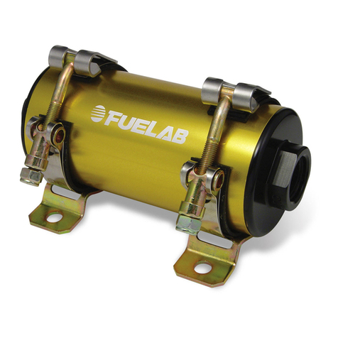
Fuelab 93903 User manual

Model Number 93903
Flange Mount Fuel Pump
Operating and Installation Instructions
C
CA
AU
UT
TI
IO
ON
N!
!
This product is to be installed only by persons knowledgeable in the repair and modification of vehicle fuel systems
and general vehicle systems modification. Only a qualified technician or mechanic who is aware of applicable
safety procedures and fabrication skills should perform the installation of this product.
This fuel pump utilizes an electronic DC motor system that is not typical of conventional fuel pumps, and therefore
extra precautions must be adhered to as contained in instructions herein
GASOLINE AND OTHER FUELS ARE FLAMMABLE AND CAN BE EXPLOSIVE!
Perform the installation in a well ventilated location only to minimize the build up of fuel vapors. NO open flames,
smoking or other sources of ignition are to be present during installation, to prevent fire or explosion that can cause
serious injury or death. Grinding, cutting, and drilling must be performed with care to prevent ignition. Draining and
removal of all fuel and ventilation of vapors in vehicle and fuel system is recommended when performing such
procedures. Proper e
y
e and personal protection is required at all times durin
g
installation.
W
WA
AR
RN
NI
IN
NG
G!
!
The Vehicle’s fuel system may be under pressure! Do not loosen any fuel connections until relieving all fuel system
pressure. Consult an applicable service manual for instructions to relieve fuel system pressure safely.
This product is intended for racing, off-road, or marine use only. This fuel system component may not be legal for
sale or use on emission controlled motor vehicles; consult local, state and national laws.
Product Contents:
Check the diagram and list of components (right)
to ensure that no components are missing from
box. Contact your Fuelab distributor immediately
for replacement.
93903 Features and Performance Ratings:
Inlet Port Size -8
A
N Militar
y
Port
Outlet Port Size -8
A
N Militar
y
Port
Fuel Cell Ports 3x -8AN Militar
y
Ports
Rated Flow Rate 132 GPH @ 45 PSI,13.5V
(
500 LPH
@
3 Bar
)
Maximum Pressure 125 PSI
(
8.5 Bar
)
Operatin
g
Volta
g
e 8-18 Volts
Maximum Current Draw 20 Amperes
WARNING!
Power Supply Voltage must be constant as specified in above specification. Only install fuel
pump on vehicles using 12 Volt (6 cell lead acid battery) with or without a normal operating alternator
charging system. Pulse-Width Modulation or other means of reducing input power voltage may result
in erratic or non-operational condition.
Before Installation, Plan Entire Fuel System:
A complete design plan of entire fuel system must be created for the specific application. These instructions are a
guide to help design this plan with respects to integrating this model of fuel pump only. Consult other sources of
information and manufacturer’s instructions for the various components of the fuel system. These instructions are
limited to general topics of fuel pump kit installation and may not include specific information pertaining to your
specific application. These instructions are written assuming the use of Multi-Point Electronic Fuel Injection using a
standard return (bypass) style fuel pressure regulator. This fuel pump kit may be integrated in some general
carbureted systems using a bypass system. Visit our company website (www.fuelab.com) for specific details
pertaining to example fuel systems and other solution ideas. Additional information including advanced
troubleshooting, any special alerts and FAQ’s pertaining to this and other products is also available. A good design
plan for the fuel system must contain consideration for: pressure and flow rate through various components, quality
of components, operating environment (temperature, vibration, shock, general exposure to elements) and local area
laws. Begin installation of fuel pump only after a complete plan is established to help avoid fuel system component
failure, costly rework, and excessive installation time.
110021253-1, No Rev Sheet 1 of 6
Fuel Pump
5x Port O-rings

Plumbing Planning Notes:
Fuel pump is intended to be mounted to the top of a fuel tank or cell. Fuel pump is to be secured by 10 bolts or
screws (4” centerline), approximately ¼” diameter. The bottom surface of the fuel pump (flange) is required to be
sealed to a fabricated fuel cell, tank or reservoir. The installer is responsible for sealing the pump and hardware at
the described flange and securing the unit and reservoir. Typically reservoir wall thickness is not adequate to
provide even clamping force, use of a ring or flange inside fuel tank or cell is required. Adequate structural
mounting and support for the fuel pump is the responsibility of the fabricator / installer. No inlet straining filter is
provided. An Inlet Straining provision (at inlet -8AN port) is required and can be fabricated using fuel compatible
material. Straining filter is recommended to be between 75 and 150 micron rating. The use of fuel line such as
stainless steel braided line and “AN” style fitting connections is recommended. For most applications, flexible fuel
line lined with PTFE (Teflon) is highly recommended. The outlet fuel port (-8AN) uses “AN” or “military” style fittings.
This plumbing standard is commonly used with racing and high performance applications. See step 4 on page 4,
for additional information on this port standard. A fuel filter with a 60 micron or finer particle rating is required to be
used upstream of regulator and downstream from fuel pump to protect it and the fuel injectors from foreign object
damage. Reference the schematic diagram below for filter location. Three available fuel cell auxiliary -8AN ports
may serve as return, fill or vent ports according to fabricator / installer discretion. Use -8AN plugs on all unused
auxiliary ports. -8AN fuel compatible o-rings are supplied with the fuel pump that are to be used with all five (5) -
8AN fuel ports. Use of a liquid filled gauge exposed to engine compartment heat is not recommended as the liquid
inside the gauge may exert measurement errors. DO NOT plumb to any gauge mounted inside the vehicle or in
passenger compartment. A line burst can spill fuel inside passenger compartment and on occupants, possibly
causing serious injury or death. An electric gauge or pressure transducer system is recommended for readings in a
passenger compartment.
Typical EFI V-8 Fuel System Plumbing Schematic Diagram:
Special Note: Use in carbureted systems require a bypass return or relief valve.
Do not "Dead Head" Fuel Pump.
Fuel Filter with 60 Micron or
Lower Particle Rating is Required.
Fuelab Filter with 6, 10 or 40
Micron Rating is Recommended.
Check Valve is required for Reduced
Vehicle Emissions and Improved
Engine Starting. Fuelab Model 858xx Series
Filter has Check Valve Assembly
Built in and is Recommended.
(2X) Fuel Rails
with Injectors
Y-Block or "T" Fitting,
to Split Flow into Two
Fuel Rail System.
Fuelab Y-Block Models
per 725xx Series are
Recommended
515xx Series are Recommended
EFI Regulator. Fuelab Models
To Engine Intake Manifold (Air),
typically.
Fuel Gauge Shown in
Gauge Port, Liquid Filled
Gauge may have Error Due
to Temperature Variations.
Fuelab Model 71501 is
recommended.
110021253-1, No Rev Sheet 2 of 6
Manufacturer's
(to seal at fuel
Ports
Recommendations
reservoir)
for Proper
Flange
Cell Vent Plumbing
3x Aux
Follow Fuel Cell
Fuel Pump
Inlet Straining Filter
fabrication shown
(not supplied)
93903 Fuel
Pump

Electrical Planning Notes:
SPECIAL NOTE: The three wires coming from the supplied fuel pump (Red, Yellow and Black 16 gage stranded
wires with Teflon insulation) come directly from the motor’s stator internal windings. The color and order of these
three wires determines the rotational direction of the fuel pump. During initial operation, direction of motor (and
therefore direction of flow) requires it to be determined. If pump is determined to be operating in reverse, swap
positions of two of the three wires with each other to reverse direction of flow. The color of the wires are not
important regarding these three motor phase wires. Reversing the direction of the pump flow direction can be done
by changing any two of the three wires. DO NOT reverse the polarity of the input DC voltage to the controller
operating the fuel pump. This will result in damage to the controller. Supplied butt splices and shrink tubes can be
used to facilitate splicing of wiring to the supplied feedthru within the fuel tank. These butt splices and shrink tubes
are intended for one time use, not for rework. Be sure to check proper fuel pump delivery direction before
committing to permanently attaching the wiring.
Reference below, for schematic wiring diagram example. Use electrical components as described including
electrical connectors that are appropriate for the operating environment of the fuel system, whether its use in street,
racing, or marine applications. Electrical connectors for the power leads must be capable of high current draw,
note all connections, wire and component rating requirements herein. Solder and use shrink wrap for wire splices
for extra reliability. Main wiring schematic diagram below shows the control of relay by ignition switch. This source
can be changed as described, or by a toggle switch. Some forms of racing have specific rules regarding electrical
switching of fuel system. Consult appropriate racing guidelines, rules and regulations.
Speed Control: A “PWM (Pulse Width Modulation) Signal” is a signal that alternates between a “High” voltage level
that is limited to approximately 5 Volts to near 0 Volts or ground level (relative to the Power Ground Wire). The
signal shape is typically a square wave (when viewed on an oscilloscope) at a fixed frequency. This signal is
measured differentially between the PWM Signal (White) Wire and the Power Ground (Black) Wire. The ratio of the
signal being “High” vs. “Low” defines the “Dwell Time” in percentage. The Controller interprets a PWM signal’s
“Dwell Time” range between 5% and 95% to communicate pump flow performance between the minimum speed
available and the maximum speed available respectively. If the Controller fails to interpret or losses the signal, the
Controller will default to the maximum speed (or flow) setting. Electronic devices such as Engine Management
Units may have an output that can produce PWM Signals compatible with this Controller. Attach this white signal
wire to ground to operate system in Full Speed Mode (not using speed control).
MAIN WIRING SCHEMATIC DIAGRAM: (Some electrical components shown are not supplied with kit)
110021253-1, No Rev Sheet 3 of 6
CIRCUIT
BREAKER
or FUSE C
NO
NC
FUEL PUMP
POWER RELAY
VEHICLE BATTERY
VEHICLE ELECTRICAL SYSTEM
IGNITION
SWITCH
or ECM
(16-20ga)
(30+A RATING)
(20A)
(12-18 VOLT SYSTEM)
FUSED
CIRCUIT
(1-5A)
(12-14ga)
(12-
14ga)
(12-14ga) BLK
RED
(18ga)
WHT
To
PWM
Signal

110021253-1, No Rev Sheet 4 of 6
Installation Steps:
1. Disconnect the ground terminal from battery and allow the vehicle’s engine and exhaust system to cool.
Relieve fuel system pressure per applicable service manual. Follow all Warnings, Cautions and Instructions
written on previous pages of these instructions.
2. Modify, remove or replace other fuel system components as required per established build plan (reference
notes on previous pages and above).
3. Remove the fuel tank or cell from the vehicle, noting all precautions regarding fuel vapors being EXPLOSIVE
on the first page herein (if applicable). Installer is responsible for all fabrication necessary to mount and seal
the fuel pump to fuel cell or fuel tank. Installer is also responsible for securing inlet straining filter (not supplied)
to -8AN inlet.
4. Install the fuel fittings (not supplied). The threads used on these fuel ports are not tapered or pipe threads. Do
not use Teflon£ thread tape or thread sealant on these threads, as this can cause leakage or introduce debris
into the fuel system. Fittings to be used with these style of ports require use of the enclosed -908 o-rings for
proper sealing. Use light oil to lubricate the o-rings just prior to installation. Install the O-rings onto the fuel
fitting first. Position the o-ring in the thread relief of the fitting. Thread fitting into fuel pump and tighten
between 5 and 15 ftꞏlbs of torque. ALL fuel line that is internal to tank MUST be fuel compatible both inside
and outside of the line. PTFE based fuel line is recommended for a long service life.
5. Upon installation of fuel tank or cell and installation of all other fuel system components, Inspect fuel system for
any contact of fuel lines or wires with other components that can cause chafing or rubbing. Secure all
components and fuel lines. Ensure that moving components of vehicle are clear.
6. Connect the vehicle’s battery. Perform initial priming: The fuel pump may require priming during initial
operation and for moment after depletion of fuel from fuel tank or cell. This action can be accomplished by
removing fuel line from fuel rail (downstream of fuel pump and filters), allowing the fuel line to empty fluid into
fuel safe container. Operate fuel pump until fuel exits fuel line. Attach fuel line back to the fuel rail after priming
fuel pump. After tightening connection, verify leak-free operation while checking fuel rail pressure. If fuel
pressure is not high enough, repeat priming procedure to ensure that fuel pump is receiving fuel from tank.
Turn on fuel pump (typically by bypassing fuel pump relay) without engine operating. ECU or engine
management computer may be controlling the relay. The ECU may only operate pump for a few seconds each
time ignition switch is set to on. The pump will have to operate several seconds (30+) to prime and drive air out
of the fuel system. Reattach fuel rail line. Start fuel system and inspect for leaks. Inspect vehicle for any leaks.
Turn off fuel system and repair any leaks that may be present before continuing.
7. When adjusting pressure, be sure that fuel pump is operating to monitor pressure. Fuelab recommends to use
a “baseline” pressure reference when adjusting the pressure (adjusting the pressure with engine off or pressure
reference line or vacuum line unhooked). The vehicle’s engine may not produce consistent vacuum during idle
to have repeatable readings.
8. After final adjustment of fuel pressure, tighten jam nut. Road test vehicle, and retest pressure upon return to
ensure accurate adjustment. After installation of this fuel pump, verify flow capacity to ensure safe levels of
flow, particularly with reduced levels of pump speed. Having insufficient flow capacity can result in an engine
lean-out condition that can cause severe engine damage. Collecting a given amount of fuel (as measured by
weight or volume) over a measured amount of time can be used to determine capacity. Collect fuel flow from
the return line to measure the amount of fuel capacity at a given operating pressure. A 20+ ampere capacity
battery charger may be used to simulate the charging system of the vehicle while engine is off. If using an
adjustable fuel pressure regulator, for boosted applications, simulate boost by raising the fuel pressure by the
amount of expected maximum boost pressure. Performing these tests will give greater accuracy for capacity
tests.

110021253-1, No Rev Sheet 5 of 6
Fuel System Maintenance Notes:
Periodic inspection and general maintenance is required for longevity and reliability of the fuel system. This action
directly affects the fuel pump's performance and reliability. Included with that are periodic inspection and/or filter
element replacement. The straining filter (upstream of pump) should be checked and cleaned at least every 30,000
miles (more often for off-road operating conditions). Replace or clean downstream filters (after pump) every year or
15,000 miles (more often for off-road operating conditions). Dirty fuel filters can block flow and adversely effect fuel
system performance as well as can directly damage the fuel pump.
Special alert for E85 Users: DO NOT use cellulose (paper) based filter elements! Water can contaminate the fuel
and break down the element, creating debris that can damage injectors and fuel pump. E85 and other oxygenated
fuels can absorb water. Long term storage of this fuel within the fuel tank of vehicle is not recommended and can
contribute to rusting of the fuel pump's tool steel components. Draining the fuel tank and replacement with small
amount of Gasoline or Kerosene (along with operating the fuel system for a small period of time) is recommended
for long term storage of the vehicle.
Troubleshooting Notes:
Problem (Symptom) Possible Causes Possible Solutions
Not operating or slight
"clicking" sound when
turned on.
x Faulty fuel pump relay.
x Faulty, dirty or corroded
terminals or improperly
sized wire.
x Debris from tank or
plumbing lodged inside
pump.
Check voltage to controller, at power terminals.
If voltage is steady and consistent (within 1/2
Volt of battery) then contact Fuelab for
assistance or repair. If voltage is inconsistent
as described, repair or replace electrical
components as required.
Not building up fuel
pressure.
x Incorrect fuel system initial
priming procedure.
x Pump operating in reverse
direction (see above).
Repeat procedure for proper priming. If
condition continues, check all plumbing
upstream (on inlet side) of fuel pump.
Leakage of fuel at inlet or
outlet fuel ports.
x Improper type of fitting
used.
If leakage is occurring between the end caps
and sleeve, contact Fuelab immediately for
repair or replacement. If leakage occurs at
fitting, be sure that the proper fitting style is
used (AN o-ring seal type ONLY!). Pipe
threaded style fittings are NOT to be used. If
proper style of fittings are being used, be sure
that o-ring is being used on fitting or replace o-
ring.
Loss of fuel pressure or
erratic pressure pulsation
after several minutes of
operation.
x Cavitation (vapor lock) due
to overheating or restricted
inlet.
Check temperature of fuel line exiting or
entering tank right after failure. If line is hot to
touch (hot, or above 120°F), then look for
sources of heat such as exhaust or fuel rail
mountings that could be conducting too much
heat. If line or fittings are not hot to the touch,
check for inlet restrictions such as improperly
vented tank, or debris blocking inlet straining
filter. Contact Fuelab, as pump may be
damaged due to improper operating condition
for repair or consultation.

110021253-1, No Rev Sheet 6 of 6
LIMITED WARRANTY
FUELAB, a division of FCP, Inc. , having its principal place of business at 1605 Eastport Plaza Drive, Suite 125,
Collinsville, IL 62234, USA ("Manufacturer") warrants its FUELAB products (the "Products") as follows:
1. Limited Warranty.
Manufacturer warrants that the Products sold hereunder will be free from defects in material and workmanship for a
period of 2 Years from the date of purchase to the original purchaser. If the Products do not conform to this Limited
Warranty during the warranty period (as herein above specified), Buyer shall notify Manufacturer in writing, or by
phone, of the claimed defects and demonstrate to Manufacturer satisfaction that said defects are covered by this
Limited Warranty. If the defects are properly reported to Manufacturer within the warranty period, and the defects
are of such type and nature as to be covered by this warranty, Manufacturer shall, at its own expense, furnish
replacement Products or, at Manufacturer's option, replacement parts for the defective Products. Removal of
Products from vehicle (Vehicle means any automotive, bike or marine transportation powered by an internal
combustion engine. This product is NOT intended or designed for use on aircraft, experimental or otherwise.),
shipping to Manufacturer and installation of the replacement Products or replacement parts shall be at Buyer's
expense.
2. Other Limits.
THE FOREGOING IS IN LIEU OF ALL OTHER WARRANTIES, EXPRESS OR IMPLIED, INCLUDING BUT NOT
LIMITED TO THE IMPLIED WARRANTIES OF MERCHANTABILITY AND FITNESS FOR A PARTICULAR
PURPOSE. Manufacturer does not warrant against damages or defects arising out of improper or abnormal use or
handling of the Products; against defects or damages arising from improper installation (where installation is by
persons other than Manufacturer), against defects in products or components not manufactured by Manufacturer,
or against damages resulting from such non-Manufacturer made products or components. Manufacturer passes on
to Buyer the warranty it received (if any) from the maker thereof of such non-Manufacturer made products or
components. This warranty also does not apply to Products upon which repairs have been effected or attempted
by persons other than pursuant to written authorization by Manufacturer.
3. Exclusive Obligation.
THIS WARRANTY IS EXCLUSIVE. The sole and exclusive obligation of Manufacturer shall be to repair or replace
the defective Products in the manner and for the period provided above. Manufacturer shall not have any other
obligation with respect to the Products or any part thereof, whether based on contract, tort, strict liability or
otherwise. Under no circumstances, whether based on this Limited Warranty or otherwise, shall Manufacturer be
liable for incidental, special, or consequential damages.
4. Other Statements.
Manufacturer's employees, representatives' and/or resellers ORAL OR OTHER WRITTEN STATEMENTS DO NOT
CONSTITUTE WARRANTIES, shall not be relied upon by Buyer, and are not a part of the contract for sale or this
limited warranty.
5. Entire Obligation.
This Limited Warranty states the entire obligation of Manufacturer with respect to the Products. If any part of this
Limited Warranty is determined to be void or illegal, the remainder shall remain in full force and effect.
6. Warranty Service
What Does This Warranty Not Cover? Any problem that is caused by abuse, misuse, or an act of God (such as a
flood) is not covered. Also, consequential and incidental damages are not recoverable under this warranty. Some
states do not allow the exclusion or limitation of incidental or consequential damages, so the above limitation or
exclusion may not apply to you.
How Do You Get Service? In order to be eligible for service under this warranty you MUST return the Warranty
Registration card, or register on-line at www.fuelab.com/warranty-registration within 30 days of purchasing the
Product.
If something goes wrong with your product contact FUELAB at 618-344-3300, or send an e-mail to:
[email protected] for a Return Authorization Number (RMA). After receiving your RMA send it postage paid, fully
insured, with a brief written description of the problem to:
FUELAB Warranty Department, 1605 Eastport Plaza Drive, Suite 125, Collinsville, IL 62234
We will inspect your Product and contact you within 72 hours of receipt to give the results of our inspection and an
estimate of the labor and/or parts charges required to fix the Product, if applicable. If covered under this limited
warranty Manufacturer will repair Product and return it to you at no cost. If the Product is NOT covered under this
warranty and if you authorize repairs, we will return the repaired Product to you COD, or prepaid via credit card,
within 72 hours. There is no charge for inspection. If return product is found to be free of defects a $25.00 shipping
and handling charge will be applied. We will return the repaired Product to you COD, or prepaid via credit card,
within 72 hours.
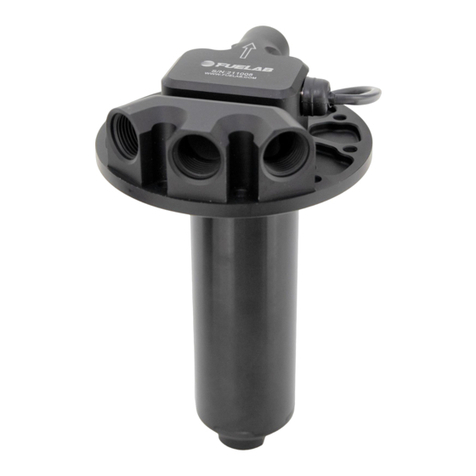
Table of contents
Other Fuelab Water Pump manuals

Fuelab
Fuelab 40401-c User manual

Fuelab
Fuelab 42401-c User manual

Fuelab
Fuelab 47401 User manual

Fuelab
Fuelab 41401-C User manual

Fuelab
Fuelab 41402-c User manual

Fuelab
Fuelab 93901 User manual

Fuelab
Fuelab 41404-c User manual

Fuelab
Fuelab 42402-c User manual

Fuelab
Fuelab 41403-c User manual

Fuelab
Fuelab 93901 User manual
Popular Water Pump manuals by other brands

Gardner Denver
Gardner Denver STP 125 Operation, maintenance and installation manual

Speck pumpen
Speck pumpen BADU Spyder I operating instructions

Wilo
Wilo Wilo-Jet-WJ Installation and operating instructions

Hozelock
Hozelock 7606 manual

IKA
IKA Vacstar control operating instructions

GORMAN-RUPP PUMPS
GORMAN-RUPP PUMPS 0 Series Installation, operation, and maintenance manual with parts list