Premier Technology DVR 1800 Series User manual
PREMIER TECHNOLOGIES, INC.
One Premier Drive
P.O.Box 159
Long Lake,MN 55356
(800) 466-8642 • (612) 475-2317
FAX: (612) 475-3579
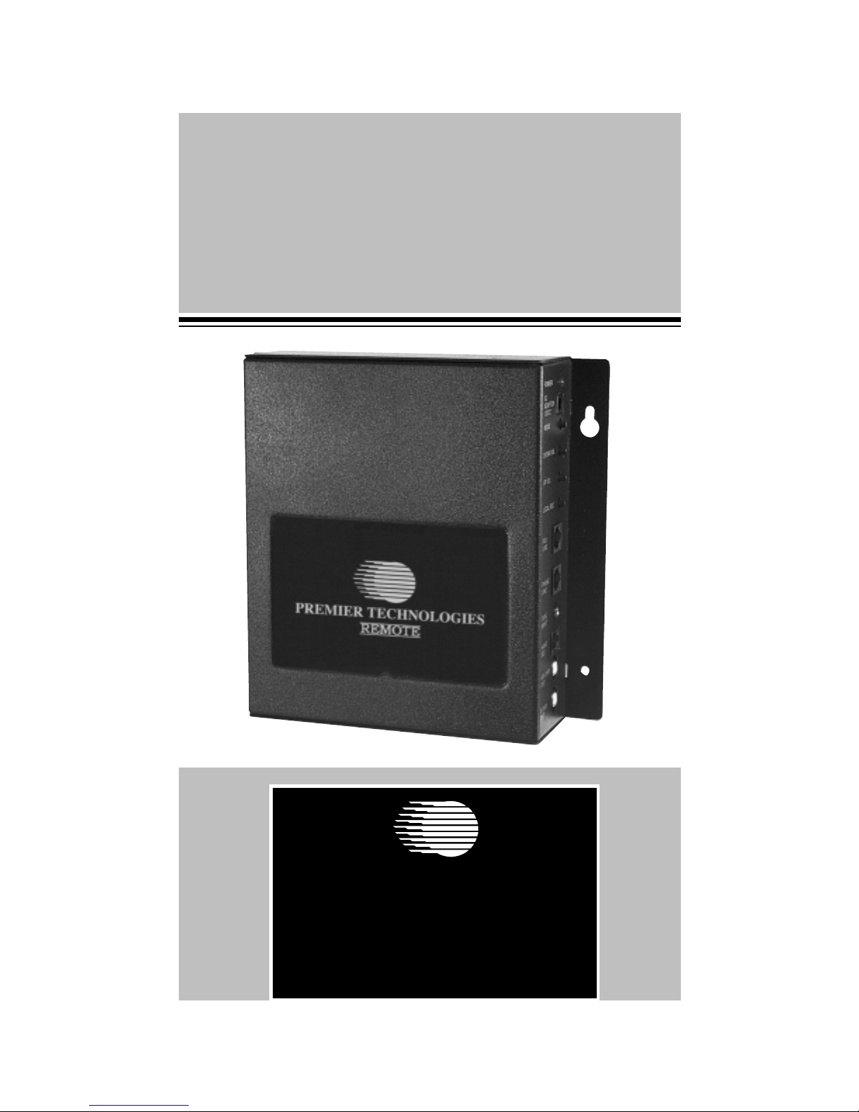
DVR 1800
Digital Voice Recorder
INSTALLATION AND
OPERATING INSTRUCTIONS

Important
Before using the Premier DVR 1800 unit, please read this
manual carefully.
Specifications:
Sample Rate:
64 kbps
Minutes of Memory:
Message length from 2 minutes to
47 minutes (model dependent).
Flash Memory:
Nonvolatile,stays unchanged.
Recording Method:
Remotely from any telephone or
locally via cassette player.
Security Code:
There is a user definable 5 digit
security code to prevent
unauthorized entry. Code is held
permanently in flash memory.
Power Source:
12VAC adaptor,included.
Wiring:
2 wire RJ-11 type,included.
Verbal Prompting:
Assists with remote loading.
Dimensions:
7.25” H x 7.5”W x 2.0”D
Ring Detection:
AC Ring,SquareWave Ring.
Weight:
4 lb.(Boxed)

1 DVR 1800 Installation and Operating Instructions
DVR 1800
FEATURES:
• The DVR will answer all incoming calls on the programmed number
of rings and play the pre-recorded message. After playback of the
message,the DVR disconnects from the phone line.The unit will also
detect“winks” from the phone company central office indicating that
the caller has hung up.The DVR will then end message playback and
disconnect from the line.
• Non-volatile flash memory is used to store the audio production and
all set-up information.(Power can be lost indefinitely without loss of
program. No battery is required.)
• Output volume control is digital for the 8 and 600 ohm ports.Volume can
be changed locally or remotely over the phone.Volume remains constant
over the phone line.(This feature is typically not used on the DVR.)
• Audio production may be downloaded locally or remotely.
• Local control function may be locked out.
• User selectable five digit security code is required to interface with
DVR remotely.
• DVR can be configured to answer on 1 to 12 rings.(default is one ring)
• A call counter keeps track of the number of incoming calls.
• Two Models to Choose From –– DVR 1800 with handset jack gives you
the flexibility to record locally from a tape player or the handset jack.
DVRT 1800 with the above features plus a programmable time of day
clock to disable call answer during business hours.The clock can be
manually disabled at any time with the mode switch.
INSTALLATION INSTRUCTIONS:
1. Connect the DVR to the phone line it will be answering.Make sure no
other products, such as modems or faxes, are connected to this line.
2. Connect the AC adaptor to a suitable 120VAC outlet and the other
end into the 12VDC jack on side of unit.
POWER
AC
ADAPTOR
12VDC
MODE
DOWN VOL
UP VOL
LOCAL REC
FAX
LINE
PHONE
LINE
TAPE
INPUT
HAND
SET
600OHM
OUT
8 OHM
OUT
AC
ADAPTOR
PHONE LINE
TO CASSETTE PLAYER OR
HANDSET FOR LOCAL RECORDING
FAX
LINE
(optional)
PREMIER TECHNOLOGIES
REMOTE

DVR 1800 Installation and Operating Instructions 2
LOCAL RECORDING
(from Tape Player or handset)
1. Plug the audio output connector of a tape player (with the message
tape inserted and ready to play) into theTAPE INPUT jack on the
side of the unit plug telephone handset with carbon mic into
handset jack.
NOTE:Stereo cables are included with the unit and will work with
either a mono or stereo source. Stereo productions should be
recorded on both channels.The DVR will record in mono.
2. Rewind tape player to the beginning of the tape.Press and hold the
LOCAL REC button for 3-5 seconds. When the red LED lamp
turns off,push the play button the tape player.When the DVR hears
sound,it will automatically begin recording and will stop recording
when it hears 5 seconds of silence.
NOTE: If an audio production is already stored in memory, the
DVR will first erase the old production and then begin recording
the new production.The LED stays on during erase and goes out
when recording is ready to start.
HINT:The DVR provides different audio tones to communicate its
activities to the user.These can be heard by plugging a speaker into
the 8 ohm output or headphones into the 600 ohm output.The
DVR will beep once when local mode is entered.It will beep once
per second while erasing and beep three quick times when erase is
completed. One last beep indicates recording has started. (Erase
time is typically one to 10 seconds.)
3. To adjust the proper record level, observe the POWER
ON/RECORDING LEVEL LED during recording.The LED goes on
for record volumes greater than -15 dB. For best results the LED
should blink during speech and loud music and be mostly off.Adjust
the volume control on the tape player for optimum record level.
4. Remove the recording cable.The DVR is now ready to answer calls.
During the recording, no sound will come out of either output.
5. To increase output volume to the 600 and 8 ohm outputs only,
momentarily press the UP VOL button for a small increase in
volume.For a larger increase in volume,press and hold the UPVOL
button. (Typically, the 600 and 8 ohm outputs are not used for
normal operation.)
6. To decrease output volume, momentarily press the DOWN VOL
button for a small decrease in volume. For a larger decrease in
volume,press and hold the DOWNVOL button.

3 DVR 1800 Installation and Operating Instructions
REMOTE OPERATION:
1. Dial the phone number of the phone line that the DVR is connected
to.The DVR will answer on the programmed number of rings (factory
default is 1 ring).
2. The DVR will answer the call and begin playing the recorded message.
If no message is recorded, the DVR will beep.
3. If the DVR is playing a message, press the (*) star key to abort the
message playing.You may need to do this more than once if a loud
passage is playing. (Only do this if a message is playing).The unit will
beep when it is ready to receive the security code password.
4. All units are shipped with a default security code password of 1,2,3,4,5.
Enter the password from the telephone keypad.The unit will say “enter
function” and will beep indicating that it has accepted the password.
Program mode has now been entered.If an incorrect code is entered,the
DVR will generate a multiple beep error tone.The user may now re-enter
the correct code. (See program menu options for a detailed list of
program features. It is recommended that the user change the security
code to prevent unauthorized entry.)
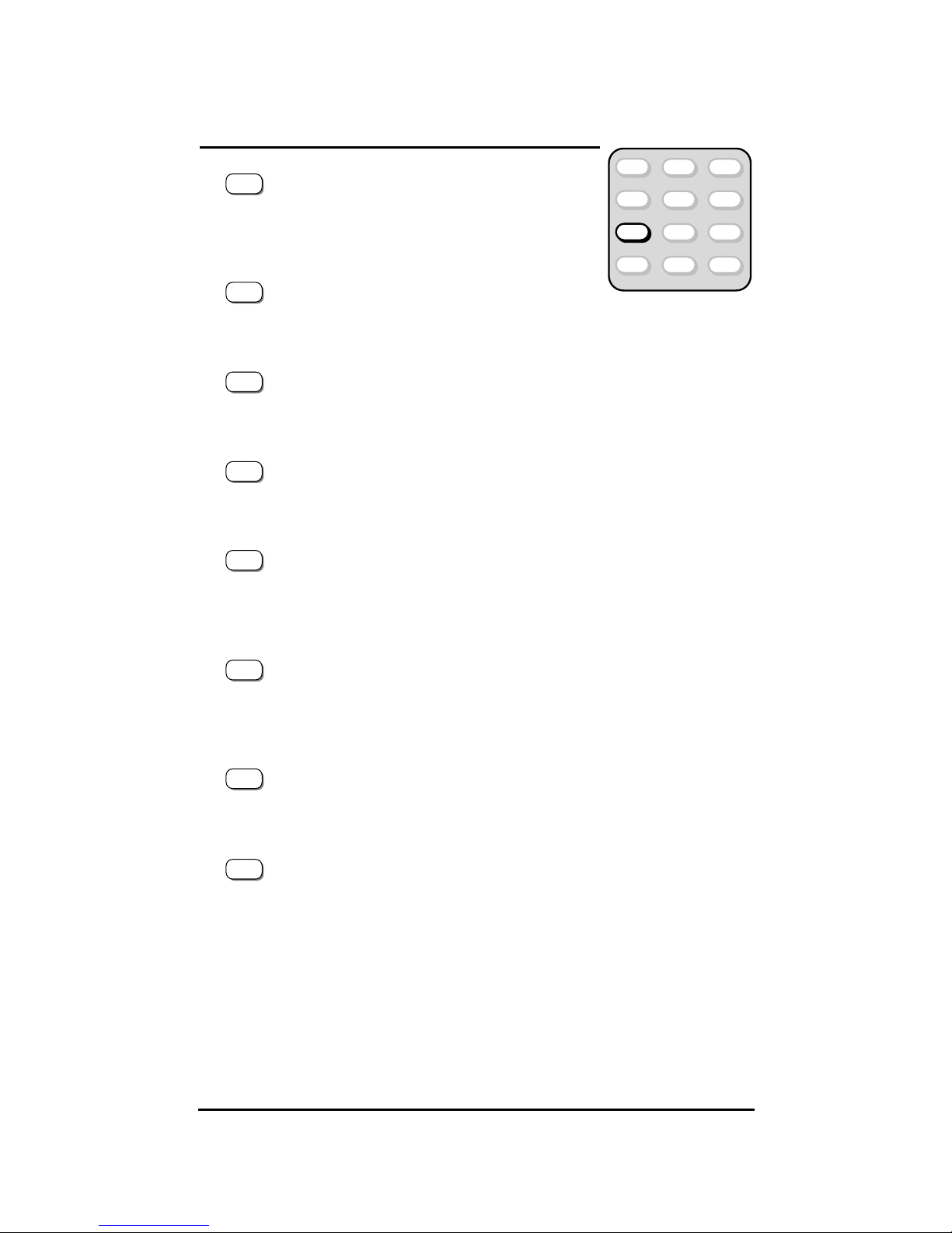
QUICK PROGRAM INSTALL:
1. Press 1 to record a test message.
• DVR says“record” and beeps
2. Say “test message” into the telephone, then press (*) star key
to stop recording.
• DVR will beep
3. Press 2 to play back the message.
• DVR will beep and play back the test message
4. Press 6 to change number of rings to answer.
• DVR says“enter ring” and beeps
5. Press 6 to answer in six rings.
• DVR says“ring is 6” and beeps
6. Press 4 to disconnect.
• DVR will beep and then hang-up

DVR 1800 Installation and Operating Instructions 4
PROGRAM MENU OPTIONS:
Press 1 Recording a message
• DVR says“record” and beeps.Unit is ready to
record.
• Play production into the telephone.
• Press (*) star key to stop recording.
• DVR will beep.It has stopped recording.
NOTE:
If an audio production is already recorded, the unit will
generate a multiple beep error tone indicating that the old
production must first be erased.
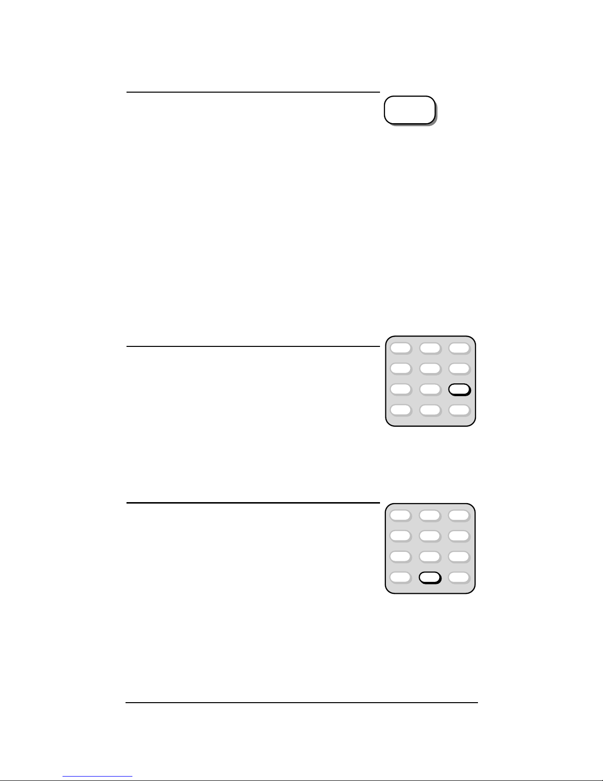
Press 2 Listen to a recording
• DVR will beep. Unit will play the recording
from memory. Audio will be played over the
phone line and on the 8 and 600 ohm outputs.
• Press (*) star key to stop playback. If you
press the (*) star key during a loud portion of
the recorded production, the DVR may not
hear the command.Just press the (*) key again.
• Change output volume during playback (Use phone keypad)
– Press 1 to increase volume
a small amount
– Press 4 to increase volume
a large amount
– Press 3 to decrease volume
a small amount
– Press 6 to decrease volume
a large amount
NOTE:
The volume will change on the 8 and 600 ohm outputs only.
The volume on the phone line will stay constant. This feature is
typically not used on a DVR.
12ABC 3DEF
4GHI 5JKL 6MNO
7PRS 8TUV 9WXY
*0
OPER
#
1
4GHI
3DEF
6MNO
12ABC 3DEF
4GHI 5JKL 6MNO
7PRS 8TUV 9WXY
*0
OPER
#

5 DVR 1800 Installation and Operating Instructions
Press 3 To Change the security code
password
• DVR says“enter code” and beeps.
• Enter new five digit security code password
from the telephone key pad.
• DVR announces the new password and beeps.
The new password is now installed.The old
password is erased.
Press 4 Leaving the DVR system
(Handing UP)
• DVR will beep and hang up.
NOTE:
The DVR will also hang up after any
30 second period of silence or inactivity.
Press 5 Erasure of the recorded message
• DVR says “erase”, it beeps and then begins
erasing the recorded message.The DVR will
beep once per second while erasing. (Erase
time is typically one to 10 seconds.Erase time
may vary.)The DVR will beep 3 times quickly
and then one more beep to indicate that
erasing is complete.
NOTE:
The security password is not erased.The setting for local
mode enable/disable is not changed. (Erasure of DVR message also
clears call counter.)
Press 6 Change number of rings to
answer
• DVR says“enter ring” and beeps.
• Enter desired ring number.
1 through 9 equals
the number of rings
* equals 10 rings
0 equals 11 rings
# equals 12 rings
• DVR announces the stored number of rings and beeps.
The number of rings to answer has changed.
12ABC 3DEF
4GHI 5JKL 6MNO
7PRS 8TUV 9WXY
*0
OPER
#
12ABC 3DEF
4GHI 5JKL 6MNO
7PRS 8TUV 9WXY
*0
OPER
#
12ABC 3DEF
4GHI 5JKL 6MNO
7PRS 8TUV 9WXY
*0
OPER
#
12ABC 3DEF
4GHI 5JKL 6MNO
7PRS 8TUV 9WXY
*0
OPER
#
*
0
OPER
#
DVR 1800 Installation and Operating Instructions 6
Press 7 Special functions
• Press 1 to hear your security
code by voice
– DVR says“code is” and then announce the
stored security code.The DVR beeps and
returns to normal programming
• Press 2 to hear your security
code by DTMF signals.
– DVR says“code is” and then beeps the security code with DTMF
tones.The DVR beeps and returns to normal programming.
• Press 3 to hear the DVR’s maximum memory size
by voice.
– DVR announces the maximum memory size in minutes.The DVR
beeps and returns to normal programming.
• Press 4 to hear the DVR’s maximum memory by
DTMF signals.
– DVR beeps then maximum memory size with DTMF tones.The
DVR beeps and returns to normal programming.
• Press 5 to hear the number of calls answered by
the DVR. (Voice output)
– DVR says“number is” and then announces the number of answered
calls.The DVR beeps and returns to normal programming.
• Press 6 to hear the number of calls answered by
the DVR. (DTMF output)
– DVR says “number is” and beeps the number of answered
calls in the DTMF tones. The DVR beeps and returns to
normal programming.
• Press 9 to disable local control. (The unit will not
respond to local download or volume changes.)
– DVR says “local off” and disables the local, up and down volume
buttons.DVR beeps and returns to normal programming.
• Press 0 to enable local control.
(This is the factory default setting.)
– DVR says“local on” and enables the local up and down volume
buttons.DVR beeps and returns to normal programming.
12ABC 3DEF
4GHI 5JKL 6MNO
7PRS 8TUV 9WXY
*0
OPER
#
1
2ABC
3DEF
4GHI
5JKL
6MNO
9WXY
0
OPER
7 DVR 1800 Installation and Operating Instructions
Press 8 To enter special functions (DVR
says ‘enter function” and beeps.)
• Press 1 to clear the stored call count to zero
– DVR says “reset number”, beeps, clears the
stored call count and returns to normal
programming.
• Press 2 to change to phone message mode.
(same as DVR 1800)
– DVR says“function 1,8 on” and beeps.Record,play,and erase address
the phone message only.
• Press 3 to change to on-hold message mode. (same as RU 2700)
– DVR says“function 2,7 on” and beeps.Record,play,and erase address
the on-hold message only.
• Press 8 to select reset mode.(no beep)
• Press 8 to confirm reset.(no beep)
– DVR says “reset” and erases all memory.All programmable functions
will be reset to factory default.(Security code is changed to default 1,
2,3,4,5;rings = 2; local control is on;audio production is erased,call
counter is cleared.) All time of day entries are erased. The DVR
returns to the normal program mode.
Press 9 Special record mode
• DVR says “record” and beeps. Unit is ready
to record.
• Play production into the telephone.
(This record mode is identical to #1 above
except that the recording will stop after 5
seconds of silence.The (*) star tone is ignored.
This mode might be used in the rare event that the audio production
contains recorded sounds that are equivalent to the (*) star key. This
would cause the recording to abort.The possible disadvantage with this
mode of recording is that a very noisy telephone line could cause the
recording to continue to the end of available memory.
Press 0 Special play mode
• The DVR will beep.Unit will play recording
from memory.
(Audio will be played on 600 and 8 ohm
outputs only, not over the phone line.)
• Press volume adjustment keys as desired
(same as #2 above.)
• Press the (*) star key to stop recording.
(This play mode is identical to #2 above except for the lack of the played
audio production over the phone line.This mode is recommended for
remote volume adjustment because the DVR unit will be listening to
volume adjustment signals only and not the played back audio production.
Adjustment signals can not be “drowned out” by loud passages in the
audio production.)
#
12ABC 3DEF
4GHI 5JKL 6MNO
7PRS 8TUV 9WXY
*0
OPER
#
12ABC 3DEF
4GHI 5JKL 6MNO
7PRS 8TUV 9WXY
*0
OPER
#

DVR 1800 Installation and Operating Instructions 8
TIME OF DAY PROGRAMMING:
(Model DVRT Only)
Press *1 Time of Day Entry
• Press *1 (star key plus“1” key).
• The DVRT says“enter local”.
• Enter the five digit time of day as (day,hr,hr,min,min) Military time.
For example:Sunday @ 11:20 pm is entered as 1, 2, 3,2,0.
• The unit beeps, indicating that the time is successfully stored.
• If an invalid day of time is entered,a multiple error beep is heard
(the time is not stored).Pressing the“#” key will cause the time of
day entry to be aborted.
Press *2 Start/Stop Entry
This operation is used to store the start and stop time of the business.A
separate start and stop time must be stored for each day of the week.To
indicated that the business is not open on a given day,enter all 9’s for the start
and stop time.When the DVRT is first received, it has all 9’s entered in the start
and stop time for each day of the week.Therefore,re-programming is required
only for days that the business is open.
• Press *2.
• The DVRT says“enter number”.
• Enter the nine digit start and stop time as (day, hr,hr,min,min,hr,
hr,min,min).This entry is organized as (day, start time,stop time).
• The unit beeps, indicating that the times are successfully stored.
Invalid entries result in an error beep.Pressing the “#” key will
cause the entry to be aborted.
Press *3 Time of Day Playback
The DVRT will verbally say the current time of day.
• Press *3.
• The DVRT says“local is” and they says the current time of day as
(day,hr,hr,min,min).
• The DVRT will say“E” for any day or time entries that are not valid.
Press *4d Start/Stop Playback
The DVRT will verbally say the current start and stop time stored for a given day.
• Press *4 plus the day number to be inquired..
• The DVRT says“number is” and then says the current start/stop
time as (day,hr,hr,min,min,hr,hr ,min,min).
This entry is organized as (day, start time,stop time).
• The DVRT will say“E” for any day or time entries that are not valid.

9 DVR 1800 Installation and Operating Instructions
MANUAL OVERRIDE OF TIME OF DAY CONTROL
(Model DVRT only)
General:
The DVRT is a standard DVR with an internal clock used to enable
or disable the answering of incoming calls according to the time of
day and the stored business hours.Remote entry is used to set the
time of day and to program business hours. Different business hours
may be entered for each day of the week.The stored information
and clock operate from an internal lithium battery so that loss of AC
power will not interrupt time keeping or lose stored information.
A mode button allows over-riding of the automatic answer
enable/disable operation.
The DVRT operates the same as a normal DVR, with the
following exceptions:
Mode Control –There are three modes of operation.The mode
of operation is controlled by pressing the mode switch a specified
number of times.The LED display will indicate which mode is active.
Auto Mode – Press the mode switch once.The LED stays
on steady.The DVRT will not answer incoming calls if the time
of day is later than the stored start time and earlier than the
stop time for that day. IF the time of day is later than the stop
time and earlier than the start time, then the DVRT will answer
incoming calls on the programmed number of rings.
“Always Answer” Mode – Press the mode switch twice
within two seconds.The LED blinks, staying on most of the time
and off only a short time.The DVRT will answer all incoming calls
on the programmed number of rings.(Use this mode when the
business is closing early or prior to holidays or extended business
closing.Be sure to switch back to auto mode prior to business
starting or calls will continue to be answered by the DVRT.)
“Never Answer” Mode – Press the mode switch three
times with less than a two second delay between switch
pressing.The LED blinks,staying off most of the time and on
only a short time.The DVRT does not answer incoming calls.
(Use this mode when business hours are extended beyond
normal or when the business will be open on normally closed
days.This will make sure that incoming calls are not answered
by the DVRT. Make sure to switch to auto mode when business
closes or any after-hours calls will not be answer.)

NOTES

Dealer Service
The network of authorized Premier Technologies dealers can provide service
backed by Premier’s technical staff. For the name of your local dealer or for
technical assistance from PremierTechnologies,contact:
Premier Technologies, Inc.
One Premier Drive,P.O. Box 159,Long Lake,MN 55356
(612) 475-2317 • (800) 466-8642
FCC PART 15 Class A Information:
This equipment uses and generates radio frequency energy.It has been tested and found to be in compliance with the limits
for a Class A computing device in accordance with the specifications in Subpart A, Part 15 of the FCC rules.These limits
are designed to prevent interference with radio and television reception in a commercial installation.
This product has passed Fcc testing. However, if it is not installed and used properly, you may notice radio and television
interference.You can minimize the chance of interference by carefully reading this manual and following the instructions for
installation and operation of the unit.
If you have installed and are using this product properly and notice interference, you should verify the source of the
interference by turning the suspected source of interference on and off. If this product is determined to be the cause of
the interference,you are encouraged to try and correct the interference by the following measures:
• Reorient or relocate the receiving antenna.
• Increase the distance between this product and the receiver.
• Connect this product to an outlet which is on a different branch circuit than the receiver.
If none of the above items correct the interference, contact an experienced radio or TV technician or your dealer for
assistance.
Warning:The user is cautioned that changes or modifications not expressly approved by the Grantee of the equipment
authorization could void the user’s authority to operate the equipment.
FCC Part 68 Registration and Repair Information:
This product has been tested and found to be in compliance with standards in Part 68 of the FCC Rules.The FCC requires
us to provide you with the following information:
1. Connection and use with the nationwide telephone network –The FCC requires that you connect your product to the
nationwide telephone network through a modular telephone outlet or jack.The modular telephone outlet or jack to
which the device must be connected is a USOC RJ-11C or RJ-11W.This equipment may not be used with Party Line
Service or with CoinTelephone Lines.
2. Notification to the telephone company – The FCC requires that upon request of your local telephone company, you
provide the FCC registration number and ringer equivalence (REN) for this equipment.This information can be found
on a label located on the bottom of this product.
3. Use of REN –The REN number is used to determine the maximum quantity of devices which may be connected to the
telephone line. Excessive REN’s on the telephone line may result in the devices not ringing in response to an incoming
call. In most but not all areas, the sum of the REN’s should be 5 or less.To be certain of the maximum allowed REN
number,contact your local telephone company.
4. Repair Instructions – If trouble is experienced with you Model 1800 series equipment, please contact Premier
Technologies,Inc.at 1-800-466-8642 for repair and (or) warranty information.
5. Rights of the telephone company – If you Model 1800 series equipment is causing harm to the telephone network,the
telephone company will notify you in advance that temporary discontinuance of service may be required. If advance
notice isn’t practical, the telephone company will notify you as soon as possible.Also, you will be advised of you right
to file a complaint with the FCC if you believe it is necessary.The telephone company may also make changes in its
facilities, equipment, operations, or procedures that could affect the operation of your equipment. If this happens, the
telephone company will provide advance notice for you to make the necessary modifications in order to maintain
uninterrupted service.
6. Requirements for hearing-aid compatibility are not applicable with this equipment.
Warranty
Upon receipt,the manufacturer will repair or replace,at its option,for a period of
three years from the date of installation, any system that proved defective in
materials or workmanship.The manufacturer is not liable for indirect,incidental or
consequential damages in connection with the use of this product.This limited
warranty does not include labor for installation or removal of unit.This warranty
is null and void if the label containing the serial number is removed.
Other manuals for DVR 1800 Series
2
Table of contents


