Presario 5710 User manual
United States December 16, 2002
Maintenance & Service Guide
Presario 5700 Series Personal Computers
Models: 5710, 5711, 5712, 5714, 5715, 5716, 5717, 5718, 5721,
5722, 5724, 5726, 5728, 5733, 5735, 5736, 5738, 5745 and 5746
MSG Index | Home | Preface | Product Description | Troubleshooting | Illustrated Parts |
Removal & Replacement | Jumpers & Switches | Specifications | Connector Pins |
Product Description
Troubleshooting
Illustrated Parts
Removal & Replacement
Jumpers & Switches
Specifications
Connector Pins
Welcome to the Presario 5700 Series Maintenance and Service Guide. This online guide is designed to serve
the needs of those whose job it is to repair Compaq products. Many of the components of the hardcopy MSG are
contained in this online guide. The Notice contains the copyright and trademark information. The Preface shows
symbol conventions, Technician Notes and Serial Number locations on the unit.
Click to download ZIP file of complete MSG to hard drive.
This MSG will be periodically maintained and updated as needed.
To report a technical problem, contact your Regional Support Center or IM Help Center.
For content comments or questions, contact Tech Support.
Top
privacy and legal statement

United States December 16, 2002
STORE | PRODUCTS | SERVICES | SUPPORT | CONTACT US |
SEARCH
Maintenance & Service Guide
Presario 5700 Series Personal Computers
Models: 5710, 5711, 5712, 5714, 5715, 5716, 5717, 5718, 5721,
5722, 5724, 5726, 5728, 5733, 5735, 5736, 5738, 5745 and 5746
Notice
The information in this guide is subject to change without notice.
COMPAQ COMPUTER CORPORATION SHALL NOT BE LIABLE FOR
TECHNICAL OR EDITORIAL ERRORS OR OMISSIONS CONTAINED
HEREIN, NOR FOR INCIDENTAL OR CONSEQUENTIAL DAMAGES
RESULTING FROM THE FURNISHING, PERFORMANCE, OR USE OF THIS
MATERIAL.
This guide contains information protected by copyright. No part of this
guide may be photocopied or reproduced in any form without prior
written consent from Compaq Computer Corporation.
© 1998 Compaq Computer Corporation.
All rights reserved. Printed in the U.S.A.
Compaq, Presario Registered U. S. Patent and Trademark Office.
Microsoft, MS-DOS, and Windows are registered trademarks of
Microsoft Corporation.
Windows 95 is a trademark of Microsoft Corporation.
Windows 98 is a trademark of Microsoft Corporation.
The software described in this guide is furnished under a license
agreement or nondisclosure agreement. The software may be used or
copied only in accordance with the terms of the agreement.
Product names mentioned herein may be trademarks and/or registered
trademarks of their respective companies.
Maintenance and Service Guide
Compaq Presario 5700 Series
Personal Computers
© 1998 Compaq Computer Corporation
privacy and legal statement

United States December 16, 2002
STORE | PRODUCTS | SERVICES | SUPPORT | CONTACT US |
SEARCH
Maintenance & Service Guide
Presario 5700 Series Personal Computers
Models: 5710, 5711, 5712, 5714, 5715, 5716, 5717, 5718, 5721,
5722, 5724, 5726, 5728, 5733, 5735, 5736, 5738, 5745 and 5746
MSG Index | Home | Preface | Product Description | Troubleshooting |
Illustrated Parts | Removal & Replacement
Jumpers & Switches | Specifications | Connector Pins | Power Cord
Requirements
Symbols
The following words and symbols mark special messages throughout this guide.
WARNING: Text set off in this manner indicates that failure to follow directions in
the warning could result in bodily harm or loss of life.
CAUTION: Text set off in this manner indicates that failure to follow directions in the
caution could result in damage to equipment or loss of data.
IMPORTANT: Text set off in this manner presents clarifying information or
specific instructions.
NOTE: Text set off in this manner presents commentary, sidelights,
or interesting points of information.
Technician Notes
WARNING: Only authorized technicians trained by Compaq should repair this
equipment. All troubleshooting and repair procedures are detailed to allow only
subassembly/module level repair. Because of the complexity of the individual boards
and subassemblies, the user should not attempt to make repairs at the component
level or to make modifications to any printed circuit board. Improper repairs can
create a safety hazard. Any indications of component replacement or printed circuit
board modifications may void any warranty.
Serial Number
When requesting information or ordering spare parts, the computer serial number should be
provided to Compaq. The serial number can be found on the rear of the computer next to the fan
grill and on the front bezel behind the drive access door.
Locating Additional Information
The following documentation is available to support this product:
●Compaq Presario documentation set
●Introducing Windows 95 Guide
●Service Training Guides
●Compaq Service Advisories and Bulletins
●Compaq QuickFind
●Compaq Service Quick Reference Guide
●Compaq Help Center
privacy and legal statement

United States December 16, 2002
STORE | PRODUCTS | SERVICES | SUPPORT | CONTACT US |
SEARCH
Maintenance & Service Guide
Presario 5700 Series Personal Computers
Models: 5710, 5711, 5712, 5714, 5715, 5716, 5717, 5718, 5721,
5722, 5724, 5726, 5728, 5733, 5735, 5736, 5738, 5745 and 5746
MSG Index | Home | Preface | Product Description | Troubleshooting | Illustrated Parts |
Removal & Replacement | Jumpers & Switches | Specifications | Connector Pins
Models and Features
Controls and Lights Index
Power Management
Power Cord Requirements
Product Description
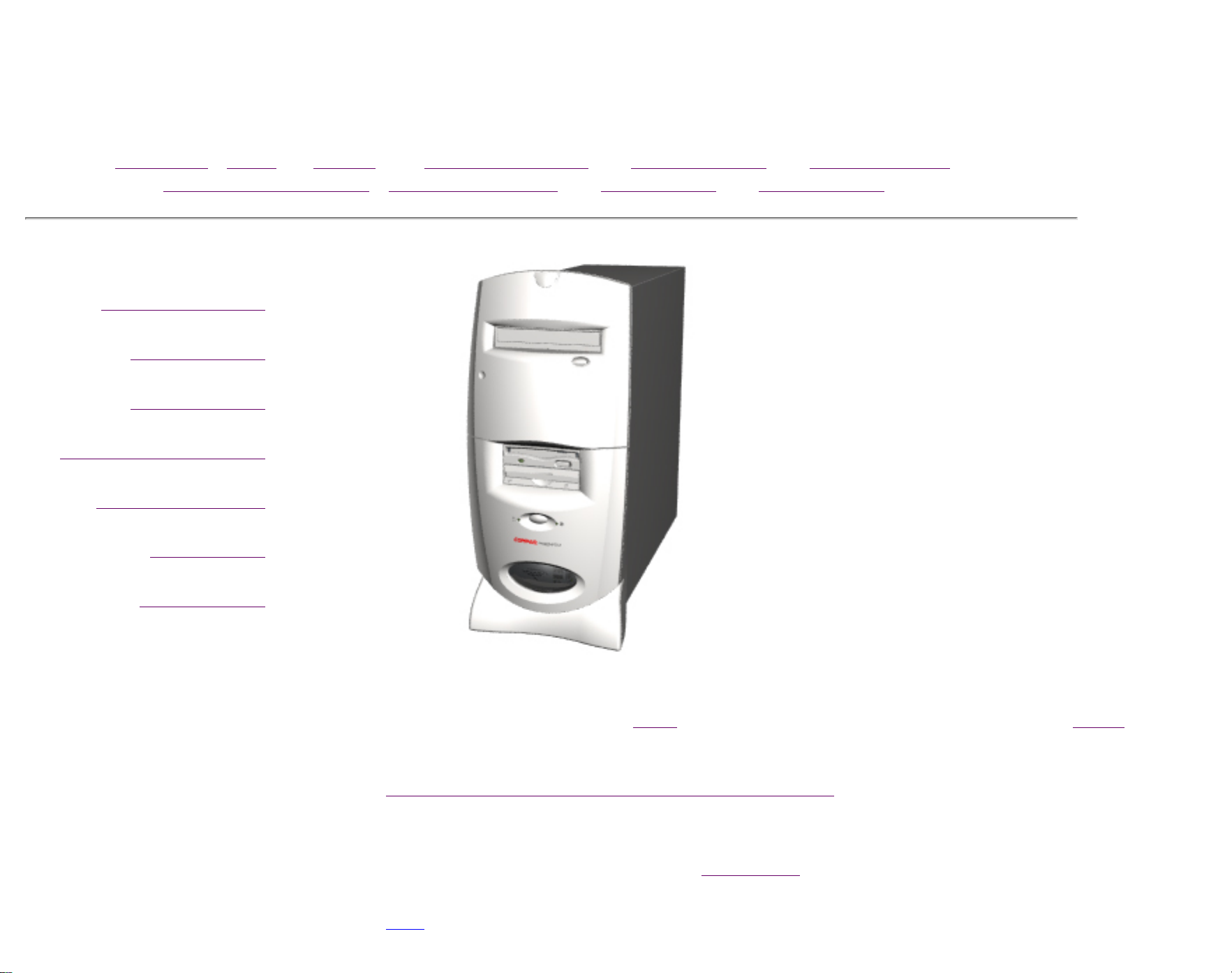
The Presario 5700 Series Internet PCs provide owners with the broadest array of choices
for high-speed access to the Internet. The new minitowers are equipped for the future
with an Industry-Standard Y2K Compliant design. Some models also provide Home
Phone line Networking that allows you to share simultaneous use of one Internet
account, printers, and more over your existing phone lines.
This section describes the model numbers and features of the Compaq Presario 5700
Series of personal computers.
privacy and legal statement
United States December 16, 2002
STORE | PRODUCTS | SERVICES | SUPPORT | CONTACT US |
SEARCH
Maintenance & Service Guide
Presario 5700 Series Personal Computers
Models: 5710, 5711, 5712, 5714, 5715, 5716, 5717, 5718, 5721,
5722, 5724, 5726, 5728, 5733, 5735, 5736, 5738, 5745 and 5746
MSG Index | Home | Preface | Product Description | Troubleshooting | Illustrated Parts |
Removal & Replacement | Jumpers & Switches | Specifications | Connector Pins |
Models and Features
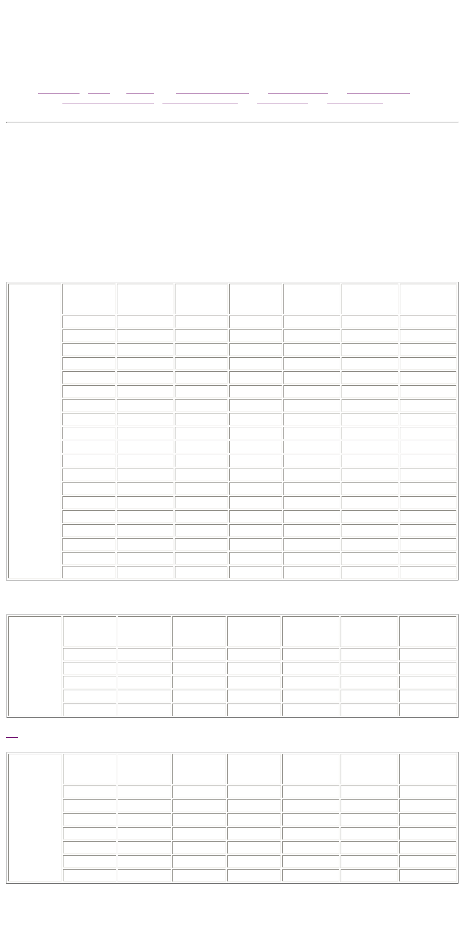
The following tables list Compaq Presario 5700 Series Personal Computer models and some model-specific features.
NOTE: ●Modem codes:
M = 1.5 Mb Digital DSL/56k V.90
K = PCI 56k V.90
GW = 56k V.90
U.S.,
Latin
America,
Canada
Model Processor
Speed
(MHz)
Memory
(MB) Hard Drive
(GB) CD/DVD Video
Memory
(MB) Fax/Modem
5710 K6-2/450 96 15 32x n/a GW
5711 CELERON/466 64 12 32x n/a GW
5712 CELERON/466 64 10 6xDVD n/a GW
5713 PIII/450 128 15 32x 8 GW
5714 CELERON/466 64 12 32x n/a GW
5715 CELERON/466 64 12 32x n/a GW
5716 PIII/450 96 15 6xDVD 8 M
5717 PIII/450 96 19 6xDVD 8 M
5721 CELERON/500 96 15 6xDVD n/a GW
5722 PIII/500 96 19 6xDVD 8 M
5724 CELERON/500 96 12 6xDVD n/a GW
5725 PIII/450 96 10 32x 8 GW
5726 PIII/500 96 19 6xDVD 8 M
5733 PIII/550 128 19 6xDVD 8 GW
5735 PIII/550 128 15 6xDVD 8 GW
5736 PIII/550 128 19 6xDVD 8 GW
5738 PIII/550 128 12 6xDVD 8 GW
5745 PIII/600 128 12 6xDVD 8 GW
5746 PIII/600 128 15 6xDVD 8 K
Top
Europe,
Middle
East, Africa
Model Processor
Speed
(MHz)
Memory
(MB) Hard Drive
(GB) CD/DVD Video
Memory
(MB) Fax/Modem
5716 PIII/450 64 10 6xDVD 8 K
5716 PIII/450 128 10 6xDVD 16 K
5722 PIII/500 128 13 6xDVD 16 K
5726 PIII/500 128 13 6xDVD 16 K
5736 PIII/550 128 17 6xDVD 16 K
Top
Asia
Pacific
Model Processor
Speed
(MHz)
Memory
(MB) Hard Drive
(GB) CD/DVD Video
Memory
(MB) Fax/Modem
5713 PIII/450 64 8 32x 8 K
5716 PIII/450 64 8 6xDVD 8 K
5716 PIII/450 64 12 6xDVD 8 K
5718 PIII/450 64 8 32x 8 K
5726 PIII/500 96 15 6xDVD 8 K
5728 PIII/500 96 12 6xDVD 8 K
5746 PIII/600 96 10 32x 8 K
Top
privacy and legal statement
United States December 16, 2002
STORE | PRODUCTS | SERVICES | SUPPORT | CONTACT US |
SEARCH
Maintenance & Service Guide
Presario 5700 Series Personal Computers
Models: 5710, 5711, 5712, 5714, 5715, 5716, 5717, 5718, 5721,
5722, 5724, 5726, 5728, 5733, 5735, 5736, 5738, 5745 and 5746
MSG Index | Home | Preface | Product Description | Troubleshooting | Illustrated Parts
|
Removal & Replacement | Jumpers & Switches | Specifications | Connector Pins |
CPU Controls & Lights
Keyboards
CPU Rear Connectors
Digital Creativity Imaging
Center (DCIC)/Creativity Action
Center (CAC)
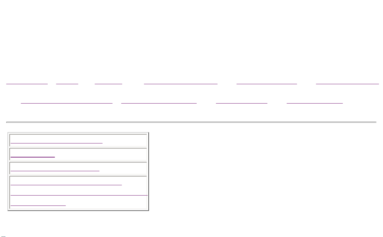
Controls and Lights Index
This section covers the computer controls and lights for the
Compaq Presario 5700 Series of personal computers. Use
the navigation bar at left to jump to specific features.
privacy and legal statement
United States December 16, 2002
STORE | PRODUCTS | SERVICES | SUPPORT | CONTACT US |
SEARCH
Maintenance & Service Guide
Presario 5700 Series Personal Computers
Models: 5710, 5711, 5712, 5714, 5715, 5716, 5717, 5718, 5721,
5722, 5724, 5726, 5728, 5733, 5735, 5736, 5738, 5745 and 5746
MSG Index | Home | Preface | Product Description | Troubleshooting | Illustrated Parts | Removal &
Replacement
Jumpers & Switches | Specifications | Connector Pins | Power Cord Requirements
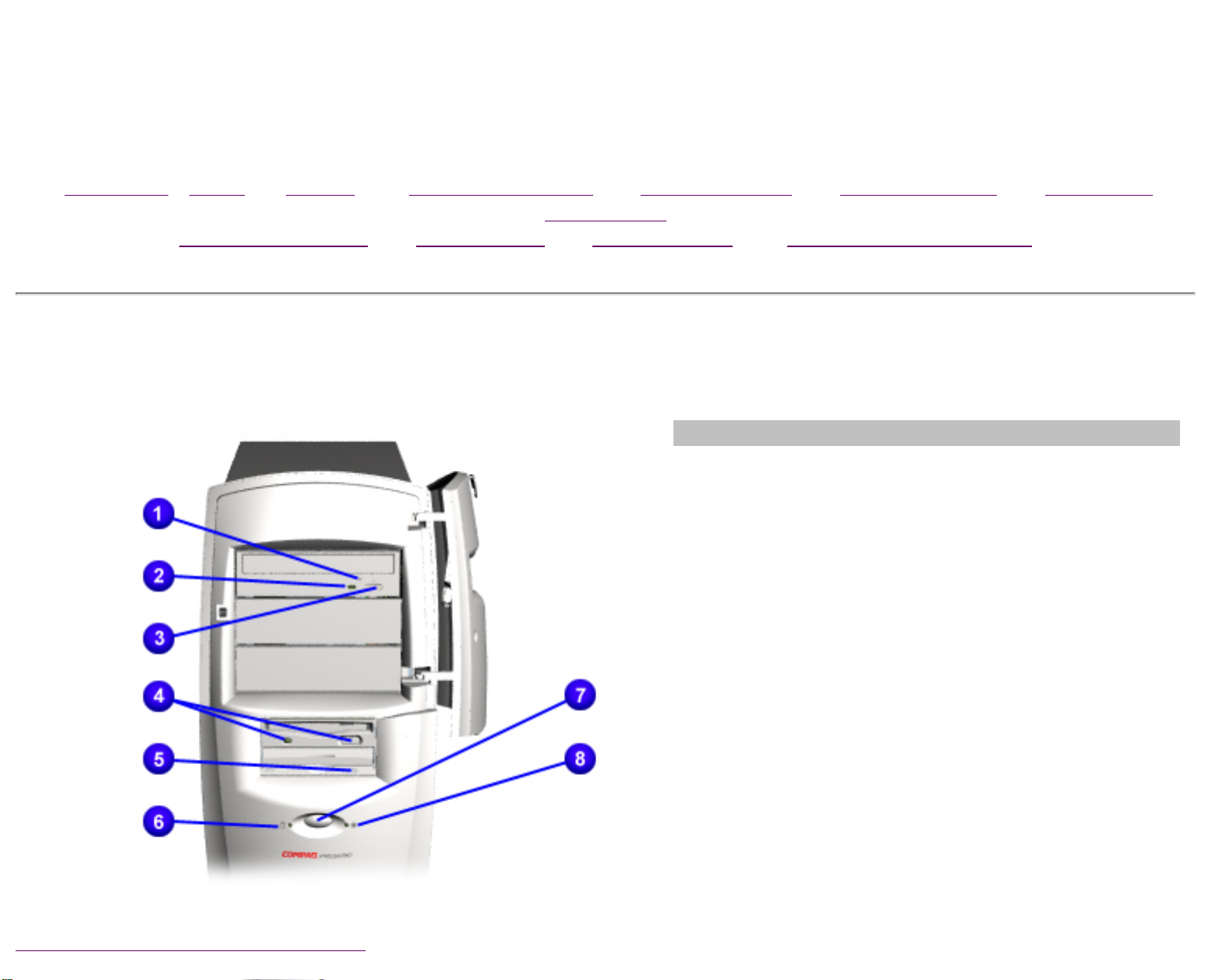
CPU Controls and Lights
Description
1CD or DVD Load/Ejection Button
2CD or DVD Drive Activity Light
3CD or DVD Manual Eject Button
4Diskette Drive Eject Button and Drive Activity
Light
5Zip Drive Eject Button and Activity Light
6Hard Drive Activity Light
7Power Button
8Power Status Light
Back to Controls and Lights Index
privacy and legal statement

United States December 16, 2002
STORE | PRODUCTS | SERVICES | SUPPORT | CONTACT US |
SEARCH
Maintenance & Service Guide
Presario 5700 Series Personal Computers
Models: 5710, 5711, 5712, 5714, 5715, 5716, 5717, 5718, 5721,
5722, 5724, 5726, 5728, 5733, 5735, 5736, 5738, 5745 and 5746
MSG Index | Home | Preface | Product Description | Troubleshooting | Illustrated Parts |
Removal & Replacement | Jumpers & Switches | Specifications | Connector Pins |
Easy Access Internet Keyboard
Easy Access Buttons Internet Suite Buttons and Keyboard Lights
Easy Access
Buttons
1Play/pause
2Rewind/Previous track
3Fast Forward/Next track
4Stop
5Eject
6Print
7Launch favorite application
8Volume down
9Mute
10 Volume up
11 Sleep
Top
Internet Suite
Buttons and
Keyboard Lights
1Instant E-Mail
2Daily Destination
3My Presario
4Instant Internet
5Instant Search
6Online Marketplace
7Retail Central
8Number Lock Light
9Caps Lock Light
10 Scroll Lock Light
Top
Back to Controls and Lights Index
privacy and legal statement

United States December 16, 2002
STORE | PRODUCTS | SERVICES | SUPPORT | CONTACT US |
SEARCH
Maintenance & Service Guide
Presario 5700 Series Personal Computers
Models: 5710, 5711, 5712, 5714, 5715, 5716, 5717, 5718, 5721,
5722, 5724, 5726, 5728, 5733, 5735, 5736, 5738, 5745 and 5746
MSG Index | Home | Preface | Product Description | Troubleshooting | Illustrated Parts
|
Removal & Replacement | Jumpers & Switches | Specifications | Connector Pins |
Product Description
CPU Rear Connectors for Models 5716, 5717, 5718, 5722,
5725, 5726, 5728, 5733, 5735, 5736, 5738, 5745 and
5746
Click here for model 5710
Click here for models 5711, 5712, 5714, 5715, 5721 and 5724
1 Mouse
connector
2 Keyboard
connector
3 USB (Universal
Serial Bus)
connectors*
4 Microphone
5 Audio in
6 Audio out
7 IEEE 1394
connector*
8 VGA connector
9 Ethernet RJ45
connector*
10 RJ11 connector
to wall*
11 RJ11 connector
to telephone*
12 AC power
connector
13 Voltage select
switch
14 Serial port
15 Parallel port
16 DFP
connector**
17 Telephone line
to wall outlet
18 Telephone line
to telephone
* On selected models
only
** Includes TV out
on EMEA models only
Back to Controls and Lights Index
privacy and legal statement

United States December 16, 2002
STORE | PRODUCTS | SERVICES | SUPPORT | CONTACT US |
SEARCH
Maintenance & Service Guide
Presario 5700 Series Personal Computers
Models: 5710, 5711, 5712, 5714, 5715, 5716, 5717, 5718, 5721,
5722, 5724, 5726, 5728, 5733, 5735, 5736, 5738, 5745 and 5746
MSG Index | Home | Preface | Product Description | Troubleshooting | Illustrated Parts
|
Removal & Replacement | Jumpers & Switches | Specifications | Connector Pins |
Digital Creativity Imaging Center/Creativity Action
Center
Description
1 Gamepad/Joystick Port
2 USB (Universal Serial
Bus) connector
3 IEEE 1394 connector (on
select models with DCIC
only)
Back to Controls and Lights Index
privacy and legal statement

United States December 16, 2002
STORE | PRODUCTS | SERVICES | SUPPORT | CONTACT US |
SEARCH
Maintenance & Service Guide
Presario 5700 Series Personal Computers
Models: 5710, 5711, 5712, 5714, 5715, 5716, 5717, 5718, 5721,
5722, 5724, 5726, 5728, 5733, 5735, 5736, 5738, 5745 and 5746
MSG Index | Home | Preface | Product Description | Troubleshooting | Illustrated Parts |
Removal & Replacement | Jumpers & Switches | Specifications | Connector Pins
Clearing CMOS
Power-On Self-Test (POST)
Diagnostic Error Codes
Troubleshooting Without Diagnostics
Troubleshooting
This section provides troubleshooting information for Compaq Presario
5700 Series Personal Computers. Power-On Self-Test (POST)
messages, diagnostic error codes, and memory error codes appear in
tables.
The message and code tables include a description of the error, the
probable cause, and the recommended action that should be taken to
resolve the error condition.
Adherence to the procedures and precautions described in this section
is essential for proper service.
privacy and legal statement

United States December 16, 2002
STORE | PRODUCTS | SERVICES | SUPPORT | CONTACT US |
SEARCH
Maintenance & Service Guide
Presario 5700 Series Personal Computers
Models: 5710, 5711, 5712, 5714, 5715, 5716, 5717, 5718, 5721,
5722, 5724, 5726, 5728, 5733, 5735, 5736, 5738, 5745 and 5746
MSG Index | Home | Preface | Product Description | Troubleshooting | Illustrated Parts
|
Removal & Replacement | Jumpers & Switches | Specifications | Connector Pins
Clearing CMOS for Models 5716, 5717, 5718,
5122, 5726, 5728, 5733, 5735, 5736, 5738, 5745
and 5746
Click here for Model 5710
Click here for Models 5711, 5712, 5714, 5715, 5721, and 5724
Password Jumper Location
If the power-on password
is not known, clearing
CMOS will disable the
power-on password. To
clear CMOS, complete the
following steps:
1.Complete the
preparation for
disassembly.
2.Remove the Chassis.
3.To disable the
password, move the
jumper
at JP1 from 1-2 to 2-3.
4.Wait for 10 seconds.
5.Move the jumper at JP1
from 2-3 to 1-2.
6.Replace the chassis and
perform the desired
troubleshooting.
privacy and legal statement
United States December 16, 2002
STORE | PRODUCTS | SERVICES | SUPPORT | CONTACT US |
SEARCH
Maintenance & Service Guide
Presario 5700 Series Personal Computers
Models: 5710, 5711, 5712, 5714, 5715, 5716, 5717, 5718, 5721,
5722, 5724, 5726, 5728, 5733, 5735, 5736, 5738, 5745 and 5746
MSG Index | Home | Preface | Product Description | Troubleshooting | Illustrated Parts
|
Removal & Replacement | Jumpers & Switches | Specifications | Connector Pins
Clearing CMOS for Models 5711, 5712, 5714,
5715, 5721, and 5724
Click here for Model 5710
Click here for Models 5716, 5717, 5718, 5122, 5726, 5728, 5733,
5735, 5736, 5738, 5745 and 5746
If the power-on password
is not known, clearing
CMOS will disable the
power-on password. To
clear CMOS, complete the
following steps:
1.Complete the
preparation for
disassembly.
2.Remove the Chassis.
3.To disable the
password, move the
jumper
at JP1 from 1-2 to 2-
3.
4.Wait for ten seconds.
5.Move the jumper at
JP1 from 2-3 to 1-2.
6.Replace the chassis
and perform the
desired
troubleshooting.
privacy and legal statement

United States December 16, 2002
STORE | PRODUCTS | SERVICES | SUPPORT | CONTACT US |
SEARCH
Maintenance & Service Guide
Presario 5700 Series Personal Computers
Models: 5710, 5711, 5712, 5714, 5715, 5716, 5717, 5718, 5721,
5722, 5724, 5726, 5728, 5733, 5735, 5736, 5738, 5745 and 5746
MSG Index | Home | Preface | Product Description | Troubleshooting | Illustrated Parts
|
Removal & Replacement | Jumpers & Switches | Specifications | Connector Pins
Power-On Self-Test (POST)
POST is a series of diagnostic tests that run automatically when the system is turned on. After
the computer is turned on, POST checks the following assemblies to ensure that the computer
system is functioning properly:
●Keyboard
●System board
●Memory modules
●Video memory
●Diskette drive
●Hard drive
●CD (or DVD) drive
●Power supply
POST also detects the type of mass storage devices installed in the computer.
If POST finds an error in the system, an error condition is indicated by an audible or visual
message.
privacy and legal statement

United States December 16, 2002
STORE | PRODUCTS | SERVICES | SUPPORT | CONTACT US |
SEARCH
Maintenance & Service Guide
Presario 5700 Series Personal Computers
Models: 5710, 5711, 5712, 5714, 5715, 5716, 5717, 5718, 5721,
5722, 5724, 5726, 5728, 5733, 5735, 5736, 5738, 5745 and 5746
MSG Index | Home | Preface | Product Description | Troubleshooting | Illustrated Parts | Removal &
Replacement
Jumpers & Switches | Specifications | Connector Pins | Power Cord Requirements
POST (Power-On Self-Test) Error Messages
An error message displays if the POST encounters a problem. This self-test will run automatically each time the
system is powered on. The self-test will check all assemblies within the computer and report any errors found.
Click on the desired error code for the probable cause of the error and a recommended course of action.
Diskette Drive A or B Error Failing Bits nnn Fixed Disk Controller Failure
Extended RAM failed at offset nnn Fixed Disk 0 or 1 Failure Incorrect Drive A Type
Invalid NVRAM Media Type Keyboard Controller Error Keyboard Error
Operating System Not Found Parity Check 1 Parity Check 2
Real Time Clock Error System Battery is Dead System BIOS Shadowed
System Cache Error System CMOS Checksum Bad System RAM Failed at Offset, nnn
System Timer Error UMB Upper Limit Segment Address
nnn Video BIOS Shadowed
Diskette Drive A or B Error
Probable Cause Recommended Action
Drive A: is present, but fails the BIOS POST diskette tests 1. Run Setup.
2. Replace the signal
cables.
3. Replace the drive.
Back to Top
Extended RAM failed at offset nnn
Probable Cause Recommended Action
Extended memory not working or not configured properly 1. Replace the memory
modules.
2. Replace the system
board.
Back to Top
Failing Bits nnn
Probable Cause Recommended Action
nnn is a map of the bits at the RAM address which failed the
memory test 1. Run Setup.
2. Replace the system
board.
Back to Top
Fixed Disk 0 or 1 Failure
Probable Cause Recommended Action
Hard drive is not working or configured properly 1. Run Setup.
2. Replace the signal cable.
3. Replace the hard drive.
Back to Top
Fixed Disk Controller Failure
Probable Cause Recommended Action
Hard drive is not working or configured properly 1. Run Setup.
2. Replace the system
board.
Back to Top
Incorrect Drive A Type
Probable Cause Recommended Action
Type of diskette drive A: not correctly identified 1. Run Setup.
2. Replace the diskette
drive.
Back to Top
Invalid NVRAM Media Type
Probable Cause Recommended Action
Problem with NVRAM (CMOS) access Replace the system board.
Back to Top
Keyboard Controller Error
Probable Cause Recommended Action
Keyboard, I/O keyboard controller
(on system board) or mouse error 1. Replace the keyboard.
2. Replace the mouse.
3. Replace the system
board.
Back to Top
Keyboard Error
Probable Cause Recommended Action
Keyboard, I/O keyboard controller
(on system board) or mouse error 1. Replace the keyboard.
2. Replace the mouse.
3. Replace the system
board.
Back to Top
Operating System Not Found
Probable Cause Recommended Action
Operating system cannot be located on
either drive A: or C: Run Setup.
Back to Top
Parity Check 1
Probable Cause Recommended Action
Parity error found in the system bus 1. Run Setup.
2. Replace the memory
modules.
3. Replace the system
board.
Back to Top
Parity Check 2
Probable Cause Recommended Action
Parity error found in the I/O bus 1. Run Setup.
2. Replace the ISA board
(modem).
Back to Top
Real Time Clock Error
Probable Cause Recommended Action
Real-time clock fails BIOS test Replace the system board.
Back to Top
System Battery is Dead
Probable Cause Recommended Action
RTC battery is dead 1. Replace the RTC battery.
2. Run Setup.
Back to Top
System BIOS Shadowed
Probable Cause Recommended Action
System BIOS copied to Shadow RAM Replace the system board.
Status message only; no
action required.
Back to Top
System Cache Error
Probable Cause Recommended Action
RAM cache failed the BIOS test Run Setup.
Back to Top
System CMOS Checksum Bad
Probable Cause Recommended Action
CMOS is corrupted or modified incorrectly Run Setup.
Back to Top
System RAM Failed at Offset, nnn
Probable Cause Recommended Action
System RAM failed Replace memory modules.
Back to Top
System Timer Error
Probable Cause Recommended Action
DMA, timers, etc. Replace the system board.
Back to Top
UMB Upper Limit Segment Address nnn
Probable Cause Recommended Action
Displays the address nnn of the upper limit
of Upper Memory Blocks, indicating released segments of the
BIOS
Run Setup.
Status message only; no
action required.
Back to Top
Video BIOS Shadowed
Probable Cause Recommended Action
Video BIOS successfully copied to shadow RAM Run Setup.
Status message only; no
action required.
Back to Top
privacy and legal statement
United States December 16, 2002
STORE | PRODUCTS | SERVICES | SUPPORT | CONTACT US |
SEARCH
Maintenance & Service Guide
Presario 5700 Series Personal Computers
Models: 5710, 5711, 5712, 5714, 5715, 5716, 5717, 5718, 5721,
5722, 5724, 5726, 5728, 5733, 5735, 5736, 5738, 5745 and 5746
MSG Index | Home | Preface | Product Description | Troubleshooting | Illustrated Parts
|
Removal & Replacement | Jumpers & Switches | Specifications | Connector Pins
Diagnostic Error Codes
Diagnostic error codes occur if the system recognizes a problem while running the Compaq
Utilities TEST program. These error codes help identify possible defective subassemblies.
IMPORTANT: Retest the system after completing each step.
If the problem has been resolved, do not
proceed with the remaining steps.
For assistance in the removal and replacement of a particular subassembly, see Removal and
Replacement Procedures.
Click on the desired error code range or corresponding test for a list of descriptions of each error
condition and actions required to resolve the error condition.
Error Code
Range Test
101-199 Processor Test
200-210 Memory Test
301-304 Keyboard Test
400-498 Parallel Printer Test
501-516 Video Display Unit Test
600-699 Diskette Drive Test
802-824 Monochrome Video Test
1101-1109 Serial Test
1201-1210 Modem Communications Test
1700-1799 Hard Drive Test
2402-2480 Video Test
3206 Audio Test
3301-3305
66xx CD or DVD Drive Test
8601 Pointing Interface Device Test
Processor Test Error Codes
Error Code Description Recommended Action
101-xx CPU test failed Replace the system board and retest.
102-xx Processor error 1. Run Computer Checkup or Setup
and retest.
2. Replace the processor and retest.
103-xx DMA controller failed Replace the system board and retest.
104-xx Interrupt controller failed Replace the system board and retest.
105-xx Port error Replace the system board and retest.
106-xx Keyboard controller self-test
failed Replace the system board and retest.
107-xx CMOS RAM test failed The following steps apply to error codes 107-
xx through 109-xx:
108-xx CMOS interrupt test failed 1. Replace the battery/clock module and
retest.
109-xx CMOS clock test failed 2. Replace the system board and retest.
110-xx Programmable timer test failed The following step applies to error codes 110-
xx through 113-01:
111-xx Refresh detect test failed Replace the system board and retest.
112-xx Speed test failed
113-01 Protected mode test failed
114-xx Speaker test failed 1. Verify the speaker connection.
2. Replace the system board and retest.
199-xx Installed devices test failed 1. Check system configuration.
2. Verify cable connections.
3. Check switch settings.
4. Run Compaq Utilities.
5. Replace the system board and retest.
Top
Memory Test Error Codes
Error
Code Description Recommended Action
200-xx Invalid memory
configuration 1. Verify memory module value compatibility.
2. Reinsert memory in the correct location.
201-xx Memory machine ID test
failed The following steps apply to error codes 201-xx and
202-xx:
202-xx Memory system ROM
checksum failed 1. Flash the ROM and retest.
2. Replace the memory and retest.
3. Replace the system board and retest.
203-xx Memory write/read test
failed The following steps apply to error codes 203-xx
through 210-xx:
204-xx Memory address test failed 1. Remove one memory module at a time until the
error message stops.
206-xx Increment pattern test
failed 2. Replace other removed modules one at a time,
testing each to ensure the error does not return.
210-xx Random pattern test failed 3. Replace the system board and retest.
Top
Keyboard Test Error Codes
Error
Code Description Recommended Action
301-xx Keyboard short test, 8042
self-test failed The following steps apply to error codes 301-xx
through 304-xx:
302-xx Keyboard long test failed 1. Check the keyboard connection. If disconnected,
turn the computer off and connect the keyboard.
303-xx Keyboard LED test, 8042
self-test failed 2. Replace the keyboard and retest.
304-xx Keyboard typematic test
failed 3. Replace the system board and retest.
Top
Parallel Printer Test Error Codes
Error
Code Description Recommended Action
401-xx Printer failed or not
connected The following steps apply to error codes 401-xx through
498-xx:
1. Connect the printer.
402-xx Printer data register failed 2. Check power to the printer.
403-xx Printer pattern test failed 3. Install the loop-back connector and retest.
498-xx Printer failed or not
connected 4. Replace system board and retest.
Top
Video Display Unit Test Error Codes
Error
Code Description Recommended Action
501-xx Video controller test failed The following step applies to error
codes
501-xx through 516-xx:
502-xx Video memory test failed Replace the system board and
retest.
503-xx Video attribute test failed
504-xx Video character set test failed
505-xx Video 80 × 25 mode 9 × 14 character cell test
failed
506-xx Video 80 × 25 mode 9 × 14 character cell test
failed
507-xx Video 40 × 25 mode test failed
508-xx Video 320 × 200 mode color set 0 test failed
509-xx Video 320 × 200 mode color set 1 test failed
510-xx Video 640 × 200 mode test failed
511-xx Video screen memory page test failed
512-xx Video gray scale test failed
514-xx Video white screen test failed
516-xx Video noise pattern test failed
Top
Diskette Drive Test Error Codes
Error
Code Description Recommended Action
600-xx Diskette ID drive types test failed The following steps apply to error
codes 600-xx through 698-xx:
601-xx Diskette format failed 1. Replace the diskette and retest.
602-xx Diskette read test failed 2. Check and/or replace the
diskette power and signal cables
and retest.
603-xx
604-xx
Diskette write, read, compare test failed
Diskette random seek test failed
3. Replace the diskette drive and
retest.
4. Replace the system board and
retest.
605-xx Diskette ID media test failed
606-xx Diskette speed test failed
607-xx Diskette wrap test failed
608-xx Diskette write-protect test failed
609-xx Diskette reset controller test failed
610-xx Diskette change line test failed
694-xx Pin 34 is not cut on 360KB diskette drive
697-xx Diskette type error
698-xx Diskette drive speed not within limits
699-xx Diskette drive/media ID error 1. Replace media.
2. Run Setup.
Top
Monochrome Video Test Error Codes
Error
Code Description Recommended Action
802-xx Video memory test failed The following step applies to error codes 802-
xx through 824-xx:
824-xx Monochrome video text mode test
failed Replace the system board and retest.
Top
privacy and legal statement
United States December 16, 2002
STORE | PRODUCTS | SERVICES | SUPPORT | CONTACT US |
SEARCH
Maintenance & Service Guide
Presario 5700 Series Personal Computers
Models: 5710, 5711, 5712, 5714, 5715, 5716, 5717, 5718, 5721,
5722, 5724, 5726, 5728, 5733, 5735, 5736, 5738, 5745 and 5746
MSG Index | Home | Preface | Product Description | Troubleshooting | Illustrated Parts
| Removal & Replacement
Jumpers & Switches | Specifications | Connector Pins | Power Cord Requirements
Diagnostic Error Codes
Diagnostic error codes occur if the system recognizes a problem while running the Compaq
Utilities TEST program. These error codes help identify possible defective subassemblies.
IMPORTANT: Retest the system after completing each step.
If the problem has been resolved, do not
proceed with the remaining steps.
For assistance in the removal and replacement of a particular subassembly, see Removal and
Replacement Procedures.
Click on the desired error code range or corresponding test for a description of each error
condition and actions required to resolve the error condition.
Error Code
Range Test
101-199 Processor Test
200-210 Memory Test
301-304 Keyboard Test
400-498 Parallel Printer Test
501-516 Video Display Unit Test
600-699 Diskette Drive Test
802-824 Monochrome Video Test
1101-1109 Serial Test
1201-1210 Modem Communications Test
1700-1799 Hard Drive Test
2402-2480 Video Test
3206 Audio Test
3301-3305
66xx CD or DVD Drive Test
8601 Pointing Interface Device Test
Top
Serial Test Error Codes
Error
Code Description Recommended Action
1101-xx Serial Port Test The following steps apply to error codes 1101-
xx through 1109-xx:
1109-xx Clock Register Test 1. Check the switch settings on the
serial/parallel device, if applicable.
2. Replace the system board and retest.
Top
Modem Communications Test Error Codes
Error
Code Description Recommended Action
1201-xx Modem Internal Loop-Back Test The following steps apply to error codes 1201-
xx through 1210-xx:
1202-xx Modem Time-Out Error 1. Refer to modem documentation for correct
Setup procedures.
1203-xx Modem External Termination Test 2. Check the modem line.
1204-xx Modem Auto Originate Test 3. Replace the modem and retest.
1206-xx Dial Multifrequency Tone Test
1210-xx Modem Direct Connect Test
Top
Hard Drive Test Error Codes
Error
Code Description Recommended Action
1700-xx Hard drive ID types test failed The following steps apply to error codes 1700-
xx through 1799-xx:
1701-xx Hard drive format test failed 1. Run Setup and verify drive type.
1702-xx Hard drive read test failed 2. Replace the hard drive signal and power
cables and retest.
1703-xx Hard drive write/read/compare
test failed 3. Replace the hard drive and retest.
4. Replace the system board and retest.
1704-xx Hard drive random seek test
failed
1705-xx Hard drive controller test failed
1706-xx Hard drive ready test failed
1707-xx Hard drive recalibration test
failed
1708-xx Hard drive format bad track test
failed
1709-xx Hard drive reset controller test
failed
1710-xx Hard drive park head test failed
1714-xx Hard drive file write test failed
1715-xx Hard drive head select test failed
1716-xx Hard drive conditional format test
failed
1717-xx Hard drive ECC* test failed
1719-xx Hard drive power mode test
failed
1730-x Fixed Disk 0 does not support
DMA Mode
1731-x Fixed Disk 1 does not support
DMA Mode
1740-x Fixed Disk 0 failed Set Block
Mode command
1741-x Fixed Disk 1 failed Set Block
Mode command
1750-x Fixed Disk 0 failed Identify
command
1751-x Fixed Disk 1 failed Identify
command
1760-x Fixed Disk 0 does not support
Block Mode
1761-x Fixed Disk 1 does not support
Block Mode
1790-x Disk 0 Configuration Error
1792-x Secondary Disk Controller Failure
1799-xx Invalid hard drive type failed
Top
DVD Drive Test Error Codes
Error Code Description Recommended Action
3301-xx
3305-xx
66XX-xx
DVD drive read test failed The following steps apply to error codes 3301-
xx through 3305-xx and 66XX-xx:
1. Replace the DVD drive and retest.*
2. Check the jumper settings on the DVD
drive.
3. Check and/or replace the power and signal
cables and retest.
4. Ensure no DVD disk is inserted when
running the CD Drive tests. This will result in
a 66xx error. This is a test issue, not a CD
drive issue .
* Boot to DOS (Command Prompt only) or Windows (Not Safe Mode). Press the DVD drive
eject button (located on the front bezel) to eject the CD and retest.
Top
Video Test Error Codes
Error Code Description Recommended Action
2402-xx Video memory test failed The following steps apply to error codes 2402-
xx through 2456-xx:
2403-xx Video attribute test failed 1. Run Setup.
2404-xx Video character set test failed 2. Replace the system board and retest.
2405-xx Video 80 × 25 mode 9 × 14
character cell test failed
2406-xx Video 80 × 25 mode 8 × 8
character cell test failed
2407-xx Video 40 × 25 mode test failed
2408-xx Video 320 × 200 mode color set
0 test failed
2409-xx Video 320 × 200 mode color set
1 test failed
2410-xx Video 640 × 200 mode test
failed
2411-xx Video screen memory page test
failed
2412-xx Video gray scale test failed
2414-xx Video white screen test failed
2416-xx Video noise pattern test failed The following steps apply to error codes 2402-
xx through 2456-xx:
2418-xx ECG/VGC memory test failed 1. Run Setup.
2419-xx ECG/VGC ROM checksum test
failed 2. Replace the system board and retest.
2420-xx ECG/VGC attribute test failed
2421-xx ECG/VGC 640 × 200 images
mode test failed
2422-xx ECG/VGC 640 × 350 16-color
set test failed
2423-xx ECG/VGC 640 × 350 64-color
set test failed
2424-xx ECG/VGC monochrome text
mode test failed
2425-xx 640 × 480 images test failure
2431-xx 640 × 480 images test failure
2432-xx 320 × 200 images (256-color
mode) test failed
2448-xx Advanced VGA Controller test
failed
2451-xx 132-column Advance VGA test
failed
2456-xx Advanced VGA 256-Color test
failed
2468-xx Advanced VGA BitBLT test The following steps apply to error codes 2468-
xx through 2480-xx:
2477-xx Advanced VGA datapath test 1. Run Setup.
2478-xx Advanced VGA BitBLT test 2. Replace the system board and retest.
2480-xx Advanced VGA Linedraw test
Top
Pointing Device Interface Test Error Codes
Error Code Description Recommended Action
8601-xx Pointing Device Interface test
failed 1. Replace with a working pointing device and
retest.
2. Replace the system board and retest.
Top
Audio Test Error Codes
Error Code Description Recommended Action
3206-xx Audio System Internal Error Replace the system board and retest.
Top
CD Drive Test Error Codes
Error Code Description Recommended Action
3301-xx
3305-xx
66XX-xx
CD drive read test failed The following steps apply to error codes 3301-
xx through 3305-xx and 66XX-xx:
1. Replace the CD and retest.
2. Check the jumper settings on the CD drive.
3. Check and/or replace the power and signal
cables and retest.
4. Replace the CD drive and retest.
5. Replace the backplane.
Top
privacy and legal statement

United States December 16, 2002
STORE | PRODUCTS | SERVICES | SUPPORT | CONTACT US |
SEARCH
Maintenance & Service Guide
Presario 5700 Series Personal Computers
Models: 5710, 5711, 5712, 5714, 5715, 5716, 5717, 5718, 5721,
5722, 5724, 5726, 5728, 5733, 5735, 5736, 5738, 5745 and 5746
MSG Index | Home | Preface | Product Description | Troubleshooting | Illustrated Parts
|
Removal & Replacement | Jumpers & Switches | Specifications | Connector Pins
Troubleshooting without Diagnostics
If you encounter some minor problem with the computer or software application, go through the
following checklist for possible solutions before running any of the Diagnostic utilities:
●Is the computer connected to a working power outlet?
●Is the computer turned on and the power light illuminated?
●Are all cables connected properly and seated?
●Are all of the necessary device drivers installed?
●Is the CONFIG.SYS file correct?
●Is the AUTOEXEC.BAT file (MS-DOS) or DOSSTART.BAT file correct?
●Was a non-bootable diskette loaded in the diskette drive at power-up?
●Are all CMOS settings correct?
Click on a selection below identify some quick checks for common problems.
Power Monitor CD Drive USB
Diskette Drive Hard Drive DVD Drive Resolving Hardware
conflicts
Solutions for Power Problems
Problem Possible Solution
Computer will not turn on Ensure that the computer is connected to a working
power source.
Computer does not automatically
display the date and time The real-time clock (RTC) battery may need to be
replaced. See Removal and Replacement
Procedures.
Computer does not beep during POST The speaker volume may have been turned down.
Push the volume control buttons on the computer
and adjust the volume or select the Volume option
from the Control Panel.
Computer powered off automatically 1. The unit may be in Sleep. If the amber light on
the front bezel is on, then the unit is in Sleep.
2. The unit temperature may have been exceeded.
Check the fan for function and blockage.
Top
Diskette Drive Problems
Problem Possible Solution
Diskette drive light stays on 1. Diskette may be damaged.
From the Windows desktop, click on the Start
button. Choose Programs=>Accessories=> System
Tools=>Scandisk to check for problems.
2. Diskette may be installed incorrectly. Remove the
diskette and reinsert.
3. Software program may be damaged. Check the
program diskettes.
Diskette drive cannot write to a
diskette 1. Diskette is not formatted. Format the diskette.
2. Diskette is write-protected. Either use another
diskette that is not write-protected, or disable the
write protection on the diskette.
3. Writing to the wrong drive. Check the drive letter
in your path statement.
4. Not enough space is left on the diskette. Use
another diskette to write the information.
Diskette drive cannot read a diskette 1. Diskette is not formatted. Format the diskette.
2. Using the wrong diskette type for the drive type.
Use a diskette that is compatible with the drive.
3. Reading the wrong drive. Check the drive letter in
your path statement.
4. Diskette drive has been disabled by Setup. Run
Setup and enable the diskette drive.
Top
Solutions for Monitor Problems
Problem Possible Solution
Characters are dim The brightness control is not set properly. Adjust the
brightness control.
Screen is blank 1. A screen-blanking (energy-saving) utility could be
installed. Press any key. If the display reappears,
you have a screen-blanking utility installed.
2. The brightness needs adjusting. Adjust the
brightness control.
3. Screen saver has been initiated. Press any key or
move the mouse to light the screen.
4. System is in Sleep mode. Press the Sleep button
to wake up.
Garbled characters on the screen
are mixed with text The ANSI.SYS driver is not in the CONFIG.SYS file.
Add the ANSI.SYS driver to the CONFIG.SYS file by
inserting the following line:
DEVICE = C:\ANSI.SYS
Monitor overheats There is not enough ventilation space for proper
airflow. Leave at least 3 inches (7.6 cm) of
ventilation space. Also, be sure there is nothing on
top of the monitor to obstruct airflow.
Cursor will not move using the
arrow keys on the numeric keypad 1. The Num Lock key is on. Press the Num Lock key.
The Num Lock light should not be on when you want
to use the arrow keys.
2. Possible application error. Restart the computer.
Top
Solutions for Hard Drive Problems
Problem Possible Solution
Hard drive error occurs Hard disk has bad sectors or has failed. Run Setup.
Reformat the hard disk.
Disk transaction problem The directory structure is bad or there is a problem
with a file.
From the Windows desktop, click on the Start
button. Choose Programs=>Accessories => System
Tools=>Scandisk to check for problems. If problems
exist, run Scandisk and click on the "Automatically
fix errors" checkbox at the bottom to correct the
problems. If a large number of lost allocation units
is found, click on the Start button. Choose
Programs=> Accessories=>System Tools=>Disk
Defragmenter.
Drive not found Cable could be loose. Check cable connections.
Nonsystem disk message 1. The system is trying to start from a diskette that
is not bootable. Remove the diskette from the
diskette drive.
2. The system is trying to start from the hard drive
but the hard disk has been damaged. Insert a
bootable diskette into the diskette drive and restart
the computer with Ctrl+Alt+Del.
3. Diskette boot has been disabled in Setup. Run
Setup and enable diskette boot.
Hard drive operation seems slow The hard disk files may be fragmented.
From the Windows desktop, click on the Start
button. Choose Programs =>Accessories è System
Tools =>Scandisk to check for problems. If
problems exist, run Scandisk and checkmark the
"Automatically fix errors" box at the bottom to
correct the problems. If a large number of lost
allocation units is found, click on the Start button.
Choose Programs => Accessories=>System
Tools=> Disk Defragmenter.
Hard drive activity light is not on,
or stays on without blinking The hard disk files may be fragmented.
From the Windows desktop, click on the Start
button. Choose Programs=> Accessories => System
Tools=>Scandisk to check for problems. If problems
exist, run Scandisk and checkmark the
"Automatically fix errors" box at the bottom to
correct the problems. If a large number of lost
allocation units is found, click on the Start button.
Choose Programs=> Accessories => System
Tools=>Disk Defragmenter.
Top
Solutions for CD Drive Problems
Problem Possible Solution
Cannot read compact disc 1. CD is not properly seated in the drive. Eject the
CD, press down on the CD firmly to correctly seat it
in the drive, then reload.
2. CD has been loaded upside down. Eject the CD,
turn it over, then reload.
3. CD may be dirty or scratched. Load another CD.
Cannot eject compact disc CD is not properly seated in the drive. Turn off the
computer, insert a thin metal rod into the
emergency eject hole, then push firmly (a
straightened paper clip can be used). Slowly pull the
tray out from the drive until the tray is fully
extended, then remove the CD.
CD drive devices are not detected;
driver is not loaded 1. CD drive is not connected properly. Open the
computer and check to see that the drive cable is
connected properly.
2. Ensure the correct driver is installed in
CONFIG.SYS.
3. If drive has been changed, make sure the jumper
setting is set for "Slave."
Top
Solutions for DVD Drive Problems
Problem Possible Solution
Cannot read DVD disk 1. DVD or CD is not properly seated in the drive.
Eject the DVD or CD, press down on the DVD or CD
firmly to correctly seat it in the drive, then reload.
2. DVD or CD has been loaded upside down. Eject
the disk, turn it over, then reload.
3. DVD or CD disk may be dirty or scratched. Load
another DVD disk.
DVD does not work in the DOS mode. Proper drivers are not loaded. Restart the system
and make sure the DVD drive drivers are loaded.
Cannot eject DVD disk 1. The system is in the Sleep mode. Press the Power
button to bring the system back to full power, then
eject the DVD.
2. The DVD, diskette, or hard drive was active when
attempting to eject the DVD. Wait until all drive
activity ends (the CD/hard drive light and diskette
drive light will go out), then try to eject the DVD.
3. DVD disk is not properly seated in the drive. Turn
off the computer, insert a thin metal rod into the
emergency eject hole (a straightened paper clip can
be used), then push firmly. Slowly pull the tray out
from the drive until the tray is fully extended, then
remove the DVD disk.
DVD drive devices are not detected;
driver is not loaded 1. DVD drive is not connected properly. Open the
computer and check to see that the drive cable is
connected properly.
2. Ensure the correct driver is installed in
CONFIG.SYS.
3. If drive has been changed, make sure the jumper
setting is set for "Slave."
Proper drivers are not loaded. Restart the system and make sure the DVD drive
drivers are loaded.
Top
Solutions for USB Problems
Problem Possible Solution
USB device does not work with the
system. The USB device and the system may use different
USB architectures. Ensure that the USB device and
the system share the same USB architecture. (UHCI-
compliant devices will only work with a UHCI-
compliant system, and OHCI-compliant devices will
only work with a OHCI-compliant system).
Top
privacy and legal statement

United States December 16, 2002
STORE | PRODUCTS | SERVICES | SUPPORT | CONTACT US |
SEARCH
Maintenance & Service Guide
Presario 5700 Series Personal Computers
Models: 5710, 5711, 5712, 5714, 5715, 5716, 5717, 5718, 5721,
5722, 5724, 5726, 5728, 5733, 5735, 5736, 5738, 5745 and 5746
MSG Index | Home | Preface | Product Description | Troubleshooting | Illustrated Parts
|
Removal & Replacement | Jumpers & Switches | Specifications | Connector Pins
Topics
System Unit
Mass Storage
Cables
Boards
Modems
Keyboards/Mouse
Monitors
Return Kits
Documentation
Illustrated Parts
This section provides illustrated parts and a reference
for spare parts numbers for Compaq Presario 5700
Series Personal Computers.
When requesting information or ordering spare parts,
the computer serial number should be provided to
Compaq. The serial number is displayed on the back
of the chassis and behind the drive cover.
privacy and legal statement

United States December 16, 2002
STORE | PRODUCTS | SERVICES | SUPPORT | CONTACT US |
SEARCH
Maintenance & Service Guide
Presario 5700 Series Personal Computers
Models: 5710, 5711, 5712, 5714, 5715, 5716, 5717, 5718, 5721,
5722, 5724, 5726, 5728, 5733, 5735, 5736, 5738, 5745 and 5746
MSG Index | Home | Preface | Product Description | Troubleshooting | Illustrated Parts
|
Removal & Replacement | Jumpers & Switches | Specifications | Connector Pins
Serial Number
The computer serial number should
be provided to Compaq whenever
requesting information or ordering
spare parts. The serial number is
located on the back 1and on the
front of the computer, behind the
drive cover.
Back to Removal and Replacement
privacy and legal statement
This manual suits for next models
18
Table of contents
Other Presario Desktop manuals


