Metacentre Y10META13.00 User manual

MANY1026A.EN – Kit, Enersoft PC Visualisation, Technical Manual
TM
Kit, Enersoft PC
Visualsation
bar

Kit, Enersoft PC Visualisation
Page 1
Contents:
1.0 Safety Precautions
1.1 Installation
1.2 Operation
1.3 Service Maintenance and Repair
2.0 Installation
2.1 Location
2.2 Power Supply
2.3 RS485 Connection
2.4 Communication Indicators
2.5 Airbus485™ Connection
2.6 Airbus485™ Communication Indicators
3.0 Selector Switches
4.0 Operational Indications
4.1 Normal Operation Example
5.0 Parts List
6.0 Technical Data
Limit of Liability
The publisher and the author make no
representation or warranties with respect to the
accuracy or completeness of the contents of this
work and specifically disclaim all warranties,
including without limitation warranties of fitness for a
particular purpose. No warranty may be created or
extended by sales or promotional materials. Neither
the publisher nor the author shall be liable for
damages arising here from. The fact that an
organisation or website is referred to in this work as
a citation and/or a potential source of further
information does not mean that the author or the
publisher endorses the information the organisation
or website may provide or recommendations it may
make. Further, readers should be aware that
internet websites listed in this work may have
changed or disappeared between when this work
was written and when it is read.
Trademarks
TM
Airmaster, the Airmaster logo, Metacentre, the
Metacentre logo, Airbus485 and the Airbus485 logo
are trademarks or registered trademarks of
Compressor & Machine Controls NV. All other
trademarks are the property of their respective
owners.
Copyright © 2010 Compressor & Machine Controls NV.
All rights reserved.

Technical Manual
Page 2
1. Safety Precautions
ALWAYS EMPLOY SAFE WORKING
PRACTISE AND PROCEDURES
WARNING: Risk of Danger
WARNING: Risk of Electric Shock
WARNING: Risk of High Pressure
WARNING: Consult Manual
When installing, commissioning, operating or
carrying out service or maintenance on a product,
personnel must use safe working practise and
observe all relevant local health and safety
requirements and regulations. Attention of users in
the UK is drawn to the Health and Safety at Work
Act, 1974, and to the Regulations and
Recommendations of the Institution of Electrical
Engineers (IEE).
Lethal voltages are used within the product. Use
extreme caution when carrying out electrical
checks. Isolate the power supply before starting any
maintenance work.
It is not possible to anticipate every circumstance
that might represent a potential hazard. If the user
employs an operating procedure, an item of
equipment or a method of working which is not
specifically recommended the user must ensure the
product will not be damaged or made unsafe and
that there is no risk to persons or property. Failure
to observe safety precautions or implement safe
working practises may be considered dangerous
practice or misuse of the product.
1.1 Installation
Installation work must only be carried out by a
competent person under qualified supervision.
A fused isolation switch must be fitted between the
main power supply and the product.
The product should be mounted in such a location
as to allow operational and maintenance access
without obstruction or hazard and to allow clear
visibility of indicators at all times.
If raised platforms are required to provide access to
the product they must not interfere with normal
operation or obstruct access. Platforms and stairs
should be of grid or plate construction with safety
rails on all open sides.
1.2 Operation
The product must only be operated by competent
personnel under qualified supervision.
Never remove or tamper with safety devices, guards
or insulation materials fitted to the unit.
The product must only be operated at the supply
voltage and frequency for which it is designed.
When mains power is switched on, lethal voltages
are present in the electrical circuits and extreme
caution must be exercised whenever it is necessary
to carry out any work on the unit.
Do not open access panels or touch electrical
components while voltage is applied unless it is
necessary for measurements, tests or adjustments.
This work must only be carried out by a qualified
electrician or technician equipped with the correct
tools and appropriate protection against electrical
hazards.
All air compressors and/or other machine
equipment connected too, and controlled by, the
product should have a warning sign attached stating
‘THIS UNIT MAY START WITHOUT WARNING'
next to the display panel.
If an air compressor and/or other machine
equipment connected too, and controlled by, the
product is to be started remotely, attach warning
signs to the machine stating ‘THIS UNIT CAN BE
STARTED REMOTELY’ in a prominent location,
one on the outside of the machine, the other inside
the machine control compartment.
1.3 Service Maintenance and Repair
Service, maintenance, repairs or modifications must
only be carried out by competent personnel under
qualified supervision.
If replacement parts are required use only genuine
parts from the original equipment manufacturer, or
an alternative approved source.
Carry out the following operations before opening or
removing any access panels or carrying out any
work on the product:
Isolate from the main electrical power supply.
Lock the isolator in the 'OFF' position and
remove the fuses.
Attach a label to the isolator switch and to the
product stating ‘WORK IN PROGRESS - DO
NOT APPLY VOLTAGE'. Do not switch on
electrical power or attempt to start the unit if
such a warning label is attached.
Ensure that all instructions concerning operation
and maintenance are strictly followed and that the
complete product, with all accessories and safety
devices, is kept in good working order.
The accuracy of sensor devices must be checked
on a regular basis. They must be renewed when
acceptable tolerances are exceeded. Always ensure
any pressure within a compressed air system is
safely vented to atmosphere before attempting to
remove or install a sensor device.
The product must only be cleaned with a damp
cloth, using mild detergents if necessary. Avoid the
use of any substances containing corrosive acids or
alkalis.
Do not paint the control facial or obscure any
indications, controls, instructions or warnings.

Kit, Enersoft PC Visualisation
Page 3
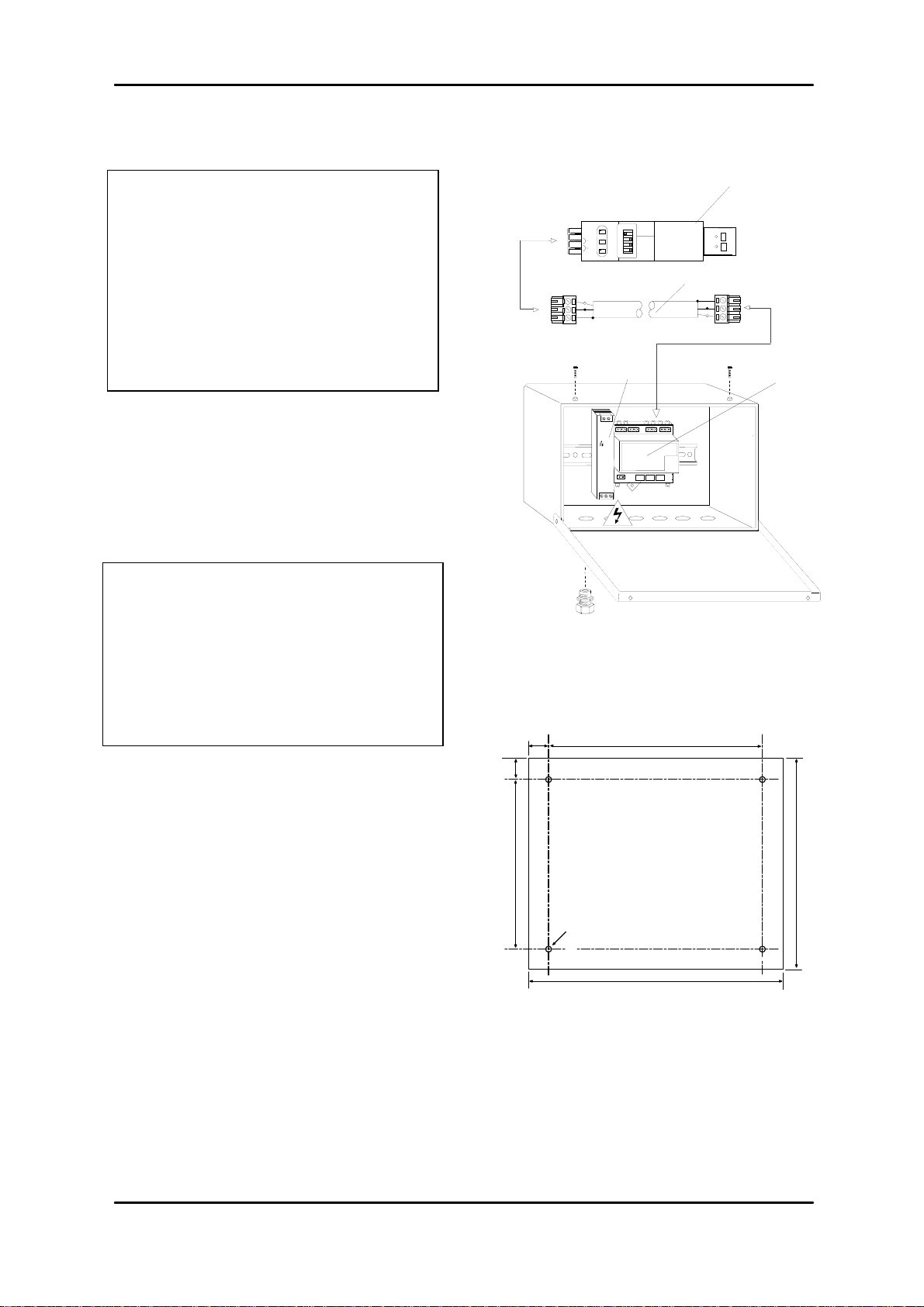
2. Installation
2.1 Location
The Kit, Enersoft PC Visualisation enclosure is
wall mounted using conventional screw
fixings.
The Kit, Enersoft PC Visualsiation must be
located within 10m of the PC and using the
supplied interconnecting cable. If other wiring
is to be used it needs to be complaint with the
specification described under 2.3 for RS485
and 2.5 for Airbus485™.
2.2 Power Supply
To maintain the Type 2 rating, the power cable
has to be routed through the cable glands.
Type 12, 12 K or 13 cable glands, conduit or
other cable entry fittings, must be used.
Apply a voltage of 100-240 Vac, 20 VA, 50- 60
Hz to the power supply AC input terminals.
A permanent earth connection to the unit’s
earth terminal block must be implemented.
2.2 RS 485
To maintain the Type 2 rating, RS485 wiring
has to be routed through the cable glands.
Type 12, 12 K or 13 cable glands, conduit or
other cable entry fittings, must be used.
2.2 Airbus™485
To maintain the Type 2 rating, RS485 wiring
has to be routed through the cable glands.
Type 12, 12 K or 13 cable glands, conduit or
other cable entry fittings, must be used.
L2 L1
L2 L1
DC
NL
Technical Manual
Page 4
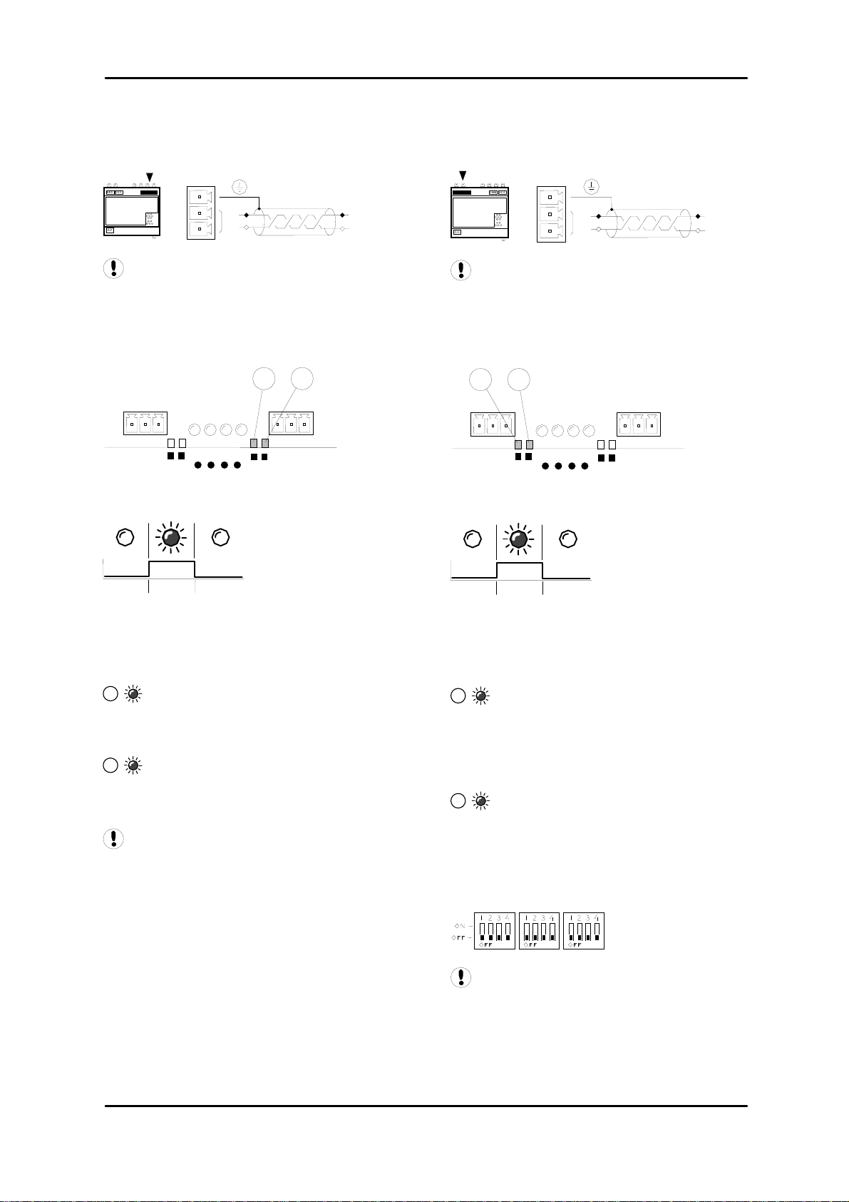
2.3 RS485 Connection
Remote RS485 Device (e.g. host PC)
Wire polarity is important
Use 2-wire, 0.3-0.5mm2, twisted pair, earth
shielded, and data cable with a total system
network length no greater than 200m (656ft).
50ms
2.4 RS485 Communication Indicators
RX – Data Received:
4A valid communication has just been
received from a remote source.
TX – Data Transmitted:
5A message has just been sent to a
remote source.
After power-up initialisation; allow a
minimum of ten (10) seconds for device
initialisation before attempting to request
information from the Airbus485™ field bus
network.
2.5 Airbus485™ System Connection
Airbus485™ field bus network
Wire polarity is important
Use 2-wire, 0.3-0.5mm2, twisted pair, earth
shielded, and data cable with a total system
network length no greater than 1.0km (3280ft).
50ms
2.6 Airbus485™ Protocol Communications
RX – Data Received:
2A valid Airbus485™ communication
has just been received from Airbus485™ field
bus network. In normal operation this event
should occur at least every two seconds.
TX – Data Transmitted:
3An Airbus485™ message has just
been sent to an Airbus485™ field bus network
device.
3. Selector Switches
Ensure all DDE Gateway selector
switches are set to the OFF position.
L2
L1 L1
L2
RS485 (B)
X02
1
2
3
L2
L1 L1
L2
RS485
X05
1
2
3
A
irbus 485™
LED #6
LED #7
LED #8
LED #9
A
irbus485
X04
LED #2
LED #3
LED #5
LED #4
X03
45
LED #6
LED #7
LED #8
LED #9
A
irbus485
X04
LED #2
LED #3
LED #5
LED #4
X03
2 3
SW SW SW
(A)

Kit, Enersoft PC Visualisation
Page 5
4. Operational Indications
1s
At power on initialisation, or when
power has been removed, all operational
indicators will fast flash for several seconds.
4.1 Normal Operation Example
Valid communications with the Airbus485™
field bus network and device(s).
6 7 8 9
6Airbus485™ Communications
OFF
No valid communications with the
Airbus485™ field bus network
ON; communicating
7OFF; no function
8OFF; no function
9Communications
OFF
No valid communications with
remote device
ON; communicating
LED #6
LED #7
LED #8
LED #9
A
irbus485™
X04
LED #2
LED #3
LED #5
LED #4
X03
7
69
8
X0
12
+24VDC /
0VDC / +-
L2
L1
RS48
5
X0
1
2
3
L2
L1
L1
L2 RS48
5
X0
1
2
3
A
irbus 485™
X0
X05 X0
2
GATEWAY, DDE
L2
L1 A
B
On
Rx
Tx
Ech
o
Termi
nato
o
USB485

Technical Manual
Page 6
RS485 data communications and other
low voltage signals can be subject to electrical
interference. This potential can result in
intermittent malfunction or anomaly that is
difficult to diagnose. To avoid this possibility
always use earth shielded cables, securely
bonded to a known good earth at one end. In
addition, give careful consideration to cable
routing during installation.
1) Never route an RS485 data
communications or low voltage signal cable
alongside a high voltage 3-phase power
supply cable. If it is necessary to cross the
path of a power supply cable(s), always cross
at a right angle.
2) If it is necessary to follow the route of power
supply cables for a short distance (for
example: from a compressor unit to a wall
along a suspended cable tray) attach the
RS485 or signal cable on the outside of an
earthed cable tray such that the cable tray
forms an earthed electrical interference shield.
3) Where possible, never route an RS485 or
signal cable near to equipment or devices that
may be a source of electrical interference (for
example: 3-phase power supply transformer,
high voltage switchgear unit, frequency
inverter drive module, radio communications
antenna).
Technical Manual
Page 8
5. Parts List
Kit, Enersoft PC Visualisation
Item Part No. Description
Y10META13.00 Kit, Enersoft PC
Visualisation
- Y01ENER03.00 CD, Enersoft
1Y10CM18.00 Gateway, DDE
2Y07CMB6.00 24VDC power supply
3Y07CM49.00 Gland, Set - Pg13.5
4Y10CM20.00 Cable, interconnect,
Gateway, DDE ~
USB485
5Y10CM21.00 USB485
6. Technical Data
Dimensions 291mm x 241mm x 152mm
Weight 6.5kg (14lb)
Mounting wall, 4 x screw fixings
Enclosure IP54, NEMA 12
Supply 230Vac +/- 10%
115Vac +/- 10%
Power 100VA
Temperature 0°C to 45°C (32°F to 112°F)
Humidity 30% to 90% RH
Non-condensing
Mounting Dimensions:
24mm 238mm
24mm
188mm
8mm Ø
236mm
286mm
on
5
3
1
V.ADJ
2
A
B
On
R
x
T
x
Echo
on
Termi-
nato
r
on
USB
RS485 USB-Nano
485
10m
on
4
Table of contents


